The International Journal of Engineering & Science is aimed at providing a platform for researchers, engineers, scientists, or educators to publish their original research results, to exchange new ideas, to disseminate information in innovative designs, engineering experiences and technological skills. It is also the Journal's objective to promote engineering and technology education. All papers submitted to the Journal will be blind peer-reviewed. Only original articles will be published.
Call Girls In Noida 959961⊹3876 Independent Escort Service Noida
The International Journal of Engineering and Science (The IJES)
1. The International Journal Of Engineering And Science (IJES)
||Volume||2 ||Issue|| 7 ||Pages|| 103-108||2013||
ISSN(e): 2319 – 1813 ISSN(p): 2319 – 1805
www.theijes.com The IJES Page 103
Improvement Of Ra Value Of Boring Operation Using Passive
Damper
Kanase Sandip S1
,Patil Jaydeep S2
,Jadhav Sainand M3
1,2,3
Asst. Professor
1,2
Bharati Vidyapeeth College of Engineering, Navi-Mumbai, Maharashtra, India
3
NBN SINHGAD School of Engineering, Pune, Maharashtra, India
---------------------------------------------------ABSTRACT-------------------------------------------------------
In industries, boring operation suffer vibrations due to high over hang of the tool. In this paper presents the
improvement of surface finish of boring operation using passive damper. By mounting this passive damper on
the standard boring bar available in the market and using the standard practice of boring operation i.e.
applying routine machining parameters an experiments were conducted on reliable CNC turning center
machine. The results obtained were found satisfactory and indicates that passive damper can be used for
minimizing the effects of vibrations which ultimately results into enhancement of surface finish.
KEYWORDS: Boring Bar, Passive Damper, Ra Value.
--------------------------------------------------------------------------------------------------------------------------------------
Date of Submission: 19 July 2013 Date of Publication: 7, July 2013
--------------------------------------------------------------------------------------------------------------------------------------
I. INTRODUCTION
In machining, boring is the process of enlarging a hole that has already been drilled (or cast), by means
of a single-point cutting tool (or of a boring head containing several such tools), for example as in boring a
cannon barrel. Boring is used to achieve greater accuracy of the diameter of a hole, and can be used to cut a
tapered hole. Boring can be viewed as the internal-diameter counterpart to turning, which cuts external
diameters.
5
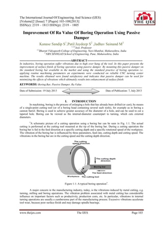
A schematic picture of a cutting operation using a boring bar can be seen in Fig. 1.1. The actual
cutting is performed at the cutting tool mounted at the tip of the boring bar. During a cutting operation the
boring bar is fed in the feed direction at a specific cutting depth and a specific rotational speed of the workpiece.
The vibration of the boring bar is influenced by three parameters, feed rate, cutting depth and cutting speed. The
vibrations in the boring bar are in the cutting speed and the cutting depth direction.
Figure 1.1: A typical boring operation5
.
A major concern in the manufacturing industry, today, is the vibrations induced by metal cutting, e.g.
turning, milling and boring operations. The vibration problem associated with metal cutting has considerable
influence on important factors such as productivity, production costs, etc. In particular, vibrations in internal
turning operations are usually a cumbersome part of the manufacturing process. Excessive vibrations accelerate
tool wear, because poor surface finish and may damage spindle bearings.
2. Improvement Of Ra Value Of Boring…
www.theijes.com The IJES Page 104
In the boring operation, vibration is a frequent problem, which affects the result of the machining, and,
in particular, the surface finish. Tool life is also influenced by vibration. Severe acoustic noise in the working
environment frequently occurs as a result of dynamic motion between the cutting tool and the work piece. In all
cutting operations like turning, boring and milling, vibrations are induced due to the deformation of the work-
piece. This implies several disadvantages, economical as well as environmental.Today the standard procedure to
avoid vibration during machining is by careful planning of the cutting parameters. The methods are usually
based on experience and trial and error to obtain suitable cutting data for each cutting operation involved in
machining a product. Machining vibration exists throughout the cutting process. While influenced by many
sources, such as machine structure, tool type, work material, etc., the composition of the machining vibration is
complicated. However, at least two types of vibrations, forced vibration and self excited vibration, were
identified as machining vibrations. Forced vibration is a result of certain periodical forces that exist within the
machine. The source of these forces can be bad gear drives, unbalanced machine-tool components,
misalignment, or motor sand pumps, etc. Self-excited vibration, which is also known as chatter, is caused by the
interaction of the chip removal process and the structure of the machine tool, which results in disturbances in the
cutting zone. Chatter always indicates defects on the machined surface; vibration especially self-excited
vibration is associated with the machined surface roughness [9,10].
II. CUTTING FORCES IN BORING OPERATION
A large number of theoretical and experimental studies on surface roughness of machined products
have been reviewed where cutting conditions (such as cutting speed, feed rate, depth of cut, tool geometry, and
the material properties of both the tool and work piece) significantly influence surface finish of the machined
parts. The surface roughness can be affected by built up edge formation. The analysis of tool vibration on
surface roughness is also investigated by some authors.
Figure 1.2: Cutting Forces in Boring Operation [6]
When the tool is in cut, the tangential (Ft) and radial (Fr) cutting forces will endeavor to deflect the tool
away from the workpiece. The tangential force will try to force the tool downwards and away from the centre
line, and in doing so will also reduce the tool clearance angle. When boring small diameter holes, it is
particularly important that the clearance angle of the insert is sufficient in order to avoid contact between tool
and wall of hole [6]
.
III. VIBRATION DAMPER
During machining operations, vibratory motion between the tool and workpiece can lead to reduced
performance. In particular, self-excited vibration, or chatter, causes poor surface finish, tool damage, and other
unwanted effects.Various passive and active techniques have been developed to improve chatter resistance.
Rivin [3]
provides a comprehensive overview of these and other issues related to the dynamic stiffness (the
product of stiffness and damping) of tools and holders. He categorizes these techniques as:
• Reduction of cutting forces
• High damping clamping devices
• Bars with anisotropic stiffness
• Periodic variation of cutting conditions
• Enhancement of structural stiffness
• Passive vibration absorbers
• Active dampers
• Active correction systems.
3. Improvement Of Ra Value Of Boring…
www.theijes.com The IJES Page 105
The passive(impact) damper has the following features: (i) small and simple in construction; (ii) easy to
mount on the main vibratory systems; and (iii) no need to adjust parameters of an impact damper to the
vibratory characteristics of the main vibratory systems[1]. Furthermore, it was clarified that by applying this
impact damper to a drill, chatter vibration could be suppressed effectively.Thus, in the present study, the
improvement of the damping capability of boring tools and suppression of chatter vibration using the impact
damper were tested. In addition, the impact damper used in this study allows a free mass to be equipped on the
outside of the main vibratory system. In the vibratory system presented in Fig.1.3, the free mass exists inside the
main mass [4,5]
Figure 1.3: Impact Damper [4,5].
IV. EXPERIMENTAL SETUP
Number of experiments was conducted to analyze the effect of vibration on surface finish. Boring bar
of 20 mm × 20 mm cross-section and 200 mm long of WIDAX make is used. The workpiece material used for
study is EN9. The boring operations were carried out on CNC turning centre of ACE make.
4.1. PASSIVE DAMPERS AND BORING TOOLS
Two Boring bar of 20 mm × 20 mm cross-section and 200 mm long of WIDAX make is used.
(A) (B) (C)
Figure 4.1 (A) Boring Bar (WIDAX) with Cermets Insert, (B) Passive Damper mounted in vertical
position on boring bar & (C) Passive Damper mounted in horizontal position on boring bar
Figure 4.2: Sample workpiece
4. Improvement Of Ra Value Of Boring…
www.theijes.com The IJES Page 106
4.2. Experimental Procedure
The work piece was mounted using a pneumatic chuck in CNC turning centre and the clamping
pressure was set as10 bar. The machining parameters like feed, depth of cut, clamping pressure, etc. were
selected based on the manufacturers recommendations and were kept constant for all the samples used. Only the
cutting speed, passive damper position on boring bar and overhang length was changed. The recommended
cutting speed, feed, depth of cut, etc. is shown in table 4.1. Boring was carried out for 105mm internal diameter
as shown in figure 4.3.
Figure 4.3: CNC turning centre
Table 4.1: Parameters
Boring tool BTA BTB
Overhang length L (mm) 40 80 120
Impact Damper position Vertical Horizontal
Clearance CL (mm) 0.4
Spindle rotation N (rpm) 80 160 240
Feed rate S (mm/min) 0.9
Depth of cut t (mm) 0.6
V. RESULTS
The figure 5.1 shows the experimental arrangement used to measure the surface roughness of bored
parts. A Mitutoyo SJ-201P apparatus was used. The profilometer technique used in this study is common in
most machine shops. For each specimen three readings were taken at approximately 1200
angles and the average
value was found out.
Figure 5.1. Surface Roughness Tester
5. Improvement Of Ra Value Of Boring…
www.theijes.com The IJES Page 107
Table 5.2 Surface Roughness or Ra values (µm)
5.2.1 Without Passive Damper:
Speed: 240 rpm, Depth of Cut: 0.6 mm and Feed: 0.09 mm/min
Sr.No. Test No.
Overhang
Length(mm)
Response (Surface finish Ra in µm)
1 2 3
1 3 40 2.72 2.72 2.73
2 2 80 2.33 2.47 2.69
3 5 120 2.82 2.90 2.60
5.2.2 With Passive Damper:
Boring bar overhang length: 40mm, Depth of Cut: 0.6 mm and Feed: 0.09 mm/min
Sr.No.
Speed
(rpm)
Test No.
Vertical Position
Test No.
Horizontal position
Response (Surface finish Ra in
µm)
Response (Surface finish Ra in
µm)
1 2 3 1 2 3
1 80 7 3.16 3.30 3.28 14 3.29 3.46 3.31
2 160 4 2.70 2.61 2.65 15 2.96 2.78 2.94
3 240 6 2.37 2.39 2.51 23 2.76 2.79 2.73
5.2.3 With Passive Damper:
Boring bar overhang length: 80mm, Depth of Cut: 0.6 mm and Feed: 0.09 mm/min
Sr.No.
Speed
(rpm)
Test
No.
Vertical Position
Test
No.
Horizontal position
Response (Surface finish Ra
in µm)
Response (Surface finish Ra
in µm)
1 2 3 1 2 3
1 80 1 2.61 2.40 2.50 16 3.14 3.27 3.35
2 160 8 2.56 2.37 2.31 21 2.38 2.47 2.71
3 240 9 2.61 2.40 2.50 22 1.26 1.38 1.56
5.2.4 With Passive Damper:
Boring bar overhang length: 120 mm, Depth of Cut: 0.6 mm and Feed: 0.09 mm/min
Sr.No.
Speed
(rpm)
Test No.
Vertical Position
Test No.
Horizontal position
Response (Surface finish Ra in µm) Response (Surface finish Ra in µm)
1 2 3 1 2 3
1 80 13 3.23 3.29 3.11 19 3.30 3.13 3.20
2 160 11 2.41 2.51 2.30 24 2.80 2.61 3.07
3 240 10 3.23 3.29 3.11 25 2.99 3.35 3.09
Figure 5.2 Plot for Without Passive Damper: Speed=240rpm
6. Improvement Of Ra Value Of Boring…
www.theijes.com The IJES Page 108
(A) (B)
Figure 5.3 (A)Plot for Vertical Position of Passive Damper: Boring bar overhang= 40mm, 80mm,
120mm & (B )Plot for Horizontal Position of Passive Damper: Boring bar overhang= 40mm,
80mm, 120mm
VI. CONCLUSION
From the results table and subsequent plots shown in section 5 following conclusions were made;
I. Significant improvement is observed between the results of surface finish obtained using boring bar
without passive (impact) damper and boring bar with passive (impact) damper.
II. In case of passive (impact) damper mounted in vertical position – with small overhang and high speed,
with large overhang and moderate speed the surfaced finish obtained is very good.
III. In case of passive (impact) damper mounted in horizontal position – with moderate overhang at all
speed values the surfaced finish obtained is very good.
An innovative method is proposed to reduce tool chatter is and enhance surface finish in boring
operation. The results prove the passive damping technique has vast potential in the reduction of tool chatter.
Also the suppression in tool chatter by using impact damper boring bars is very significant. Boring bars with
impact damping are also relatively cheaper than other damped boring bars. It is therefore concluded that impact
damping has a good effect in improving surface finish in boring operation.
REFERENCES
[1] Rajender Singh, Introduction to Basic Manufacturing Processes and Workshop Technology, New Age Publication, 2006
[2] Ronald Walsh and Denis Cormier, McGraw Hill Machining and Metalworking Handbook, 3rd
Edition, McGraw Hill Publication,
2006
[3] Rivin E., Tooling structure: interface between cutting edge and machine tool, Annals of the CIRP 2000; 49(2):591–634.
[4] S. Ema and E Maru, Damping characteristics of an impact damper and its application, Int. J. Math. Tools Manufact. Vol. 36, No.
3. pp. 293-306, 1996.
[5] L. Andren and L. Hakansson, Active Vibration Control of Boring Bar Vibrations, Blekinge Institute of Technology, Sweden,
August, 2004.
[6] Sandvik coroment, How to reduce vibration in metal cutting.
[7] Satoshi Ema, Etsuo Marui, Suppression of chatter vibration of boring tools using impact dampers, International Journal of
Machine Tools & Manufacture 40 (2000) 1141–1156.
[8] M. Senthilkumar, K. M. Mohanasundaram and B. Sathishkumar, A case study on vibration control in a boring bar using particle
damping, International Journal of Engineering, Science and Technology Vol. 3, No. 8, 2011, pp. 177-184.
[9] M.R. Duncan, C.R. Wassgren, C.M. Krousgrill, The damping performance of a single particle impact damper, Journal of Sound
and Vibration 286 (2005) 123–144.
[10] Steven E. Olson, An analytical particle damping model, Journal of Sound and Vibration 264 (2003) 1155–1166.
[11] B. Moetakef-Imani, N.Z.Yussefian, Dynamic simulation of boring process, International Journal of Machine Tools &
Manufacture 49 (2009) 1096–1103.
[12] B. Sathishkumar, K. M. Mohana Sundaram, and M. Senthil Kumar, Experimental Studies on Impact of Particle Damping on
Surface Roughness of Machined Components in Boring Operation, European Journal of Scientific Research ISSN 1450-216X
Vol.71 No.3 (2012), pp. 327-337.
[13] S. Chatterjee, On the principle of impulse damper: A concept derived from impact damper, Journal of Sound and Vibration 312
(2008) 584–605.
[14] R. D. Friend and V. K. Kinra, Particle Impact Damping, Journal of Sound and Vibration (2000) 233(1), 93}118.
[15] K. Ramesh, T. Alwarsamy, Investigation of Modal Analysis in the Stability of Boring Tool using Double Impact Dampers Model
Development, ISSN 1450-216X Vol.80 No.2 (2012), pp.182-190.
[16] L. Andren, L. Hakansson, A. Brandt, I. Claesson, Identification of motion of cutting tool vibration in a continuous boring
operation-correlation to structural properties, Mechanical Systems and Signal Processing 18 (2004) 903–927.
[17] L. Andren, L. Hakansson, A. Brandt, I. Claesson, Identification of dynamic properties of boring bar vibrations in a continuous
boring operation, Mechanical Systems and Signal Processing 18 (2004) 869–901.
[18] Safeen Y. Kassab and Younis K. Khoshnaw, The Effect of Cutting Tool Vibration on Surface Roughness of Workpiece in Dry
Turning Operation, Engineering. & Technology, Vol.25, No.7, 2007
![Improvement Of Ra Value Of Boring…
www.theijes.com The IJES Page 104
In the boring operation, vibration is a frequent problem, which affects the result of the machining, and,
in particular, the surface finish. Tool life is also influenced by vibration. Severe acoustic noise in the working
environment frequently occurs as a result of dynamic motion between the cutting tool and the work piece. In all
cutting operations like turning, boring and milling, vibrations are induced due to the deformation of the work-
piece. This implies several disadvantages, economical as well as environmental.Today the standard procedure to
avoid vibration during machining is by careful planning of the cutting parameters. The methods are usually
based on experience and trial and error to obtain suitable cutting data for each cutting operation involved in
machining a product. Machining vibration exists throughout the cutting process. While influenced by many
sources, such as machine structure, tool type, work material, etc., the composition of the machining vibration is
complicated. However, at least two types of vibrations, forced vibration and self excited vibration, were
identified as machining vibrations. Forced vibration is a result of certain periodical forces that exist within the
machine. The source of these forces can be bad gear drives, unbalanced machine-tool components,
misalignment, or motor sand pumps, etc. Self-excited vibration, which is also known as chatter, is caused by the
interaction of the chip removal process and the structure of the machine tool, which results in disturbances in the
cutting zone. Chatter always indicates defects on the machined surface; vibration especially self-excited
vibration is associated with the machined surface roughness [9,10].
II. CUTTING FORCES IN BORING OPERATION
A large number of theoretical and experimental studies on surface roughness of machined products
have been reviewed where cutting conditions (such as cutting speed, feed rate, depth of cut, tool geometry, and
the material properties of both the tool and work piece) significantly influence surface finish of the machined
parts. The surface roughness can be affected by built up edge formation. The analysis of tool vibration on
surface roughness is also investigated by some authors.
Figure 1.2: Cutting Forces in Boring Operation [6]
When the tool is in cut, the tangential (Ft) and radial (Fr) cutting forces will endeavor to deflect the tool
away from the workpiece. The tangential force will try to force the tool downwards and away from the centre
line, and in doing so will also reduce the tool clearance angle. When boring small diameter holes, it is
particularly important that the clearance angle of the insert is sufficient in order to avoid contact between tool
and wall of hole [6]
.
III. VIBRATION DAMPER
During machining operations, vibratory motion between the tool and workpiece can lead to reduced
performance. In particular, self-excited vibration, or chatter, causes poor surface finish, tool damage, and other
unwanted effects.Various passive and active techniques have been developed to improve chatter resistance.
Rivin [3]
provides a comprehensive overview of these and other issues related to the dynamic stiffness (the
product of stiffness and damping) of tools and holders. He categorizes these techniques as:
• Reduction of cutting forces
• High damping clamping devices
• Bars with anisotropic stiffness
• Periodic variation of cutting conditions
• Enhancement of structural stiffness
• Passive vibration absorbers
• Active dampers
• Active correction systems.](data:image/gif;base64,R0lGODlhAQABAIAAAAAAAP///yH5BAEAAAAALAAAAAABAAEAAAIBRAA7)