

Empfohlen
Weitere ähnliche Inhalte
Andere mochten auch
Andere mochten auch (20)
Ähnlich wie Euro uap
Ähnlich wie Euro uap (16)
Mehr von Chhay Teng
Mehr von Chhay Teng (20)
Euro uap
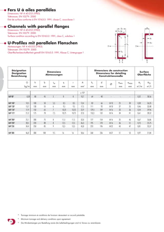
- 1. Fers U à ailes parallèles Dimensions: NF A 45-255 (1983) Tolérances: EN 10279: 2000 Etat de surface conforme à EN 10163-3: 1991, classe C, sous-classe 1 Channels with parallel flanges b e Dimensions: NF A 45-255 (1983) ss 45o Tolerances: EN 10279: 2000 Surface condition according to EN 10163-3: 1991, class C, subclass 1 r ys U-Profiles mit parallelen Flanschen h d hi ym Abmessungen: NF A 45-255 (1983) y y Toleranzen: EN 10279: 2000 tw Oberflächenbeschaffenheit gemäß EN 10163-3: 1991, Klasse C, Untergruppe 1 z tf z Désignation Dimensions de construction Dimensions Surface Designation Dimensions for detailing Abmessungen Oberfläche Bezeichnung Konstruktionsmaße G h b tw tf r A hi d emin emax AL AG Ø kg/m mm mm mm mm mm mm 2 mm mm mm mm m /m 2 m2/t x 102 UAP 80* 8,38 80 45 5 8 8 10,7 64 48 - - - 0,32 38,56 UAP 100* 10,5 100 50 5,5 8,5 8,5 13,4 83 66 M 10 25 30 0,38 36,35 UAP 130* 13,7 130 55 6 9,5 9,5 17,5 111 92 M 10 27 35 0,46 33,48 UAP 150* 17,9 150 65 7 10,25 10,25 22,9 129,5 109 M 16 33 36 0,54 29,96 UAP 175* 21,2 175 70 7,5 10,75 10,75 27,0 153,5 132 M 16 34 41 0,61 28,52 UAP 200* 25,1 200 75 8 11,5 11,5 32,0 177 154 M 16 35 46 0,67 26,86 UAP 220* 28,5 220 80 8 12,5 12,5 36,3 195 170 M 16 36 51 0,73 25,75 UAP 250 34,4 250 85 9 13,5 13,5 43,8 223 196 M 22 43 47 0,81 23,57 UAP 300 46,0 300 100 9,5 16 16 58,6 268 236 M 27 51 53 0,97 21,04 * Tonnage minimum et conditions de livraison nécessitent un accord préalable. * Minimum tonnage and delivery conditions upon agreement. 78 * Die Mindestmengen pro Bestellung sowie die Lieferbedingungen sind im Voraus zu vereinbaren.
- 2. Notations pages 211-215 / Bezeichnungen Seiten 211-215 Valeurs statiques / Section properties / Statische Kennwerte UAP Classification Désignation EN 10113-3:1993 EN 10025:1993 EN 10225:2001 axe fort y-y axe faible z-z ENV 1993-1-1 Designation Bezeichnung strong axis y-y weak axis z-z pure pure starke Achse y-y schwache Achse z-z bending y-y compression G Iy Wel.y Wpl.y■ iy Avz Iz Wel.z Wpl.z’ iz ss It Iw ys ym S 235 S 355 S 235 S 355 4 3 3 2 4 3 3 4 6 kg/m mm mm mm mm mm mm mm mm mm mm mm mm mm mm x 104 x 103 x 103 x 10 x 102 x 104 x 103 x 103 x 10 x 104 x 109 x 10 x 10 UAP 80 8,38 107,1 26,78 31,87 3,17 4,51 21,33 7,38 13,64 1,41 17,7 1,90 0,18 1,61 3,17 1 1 1 1 ✔ UAP 100 10,5 209,5 41,90 49,59 3,96 6,07 32,83 9,95 18,47 1,57 19,0 2,65 0,45 1,70 3,38 1 1 1 1 ✔ UAP 130 13,7 459,6 70,70 83,51 5,12 8,52 51,34 13,78 25,55 1,71 21,1 4,15 1,22 1,77 3,56 1 1 1 1 ✔ UAP 150 17,9 796,1 106,1 125,3 5,90 11,28 93,25 20,97 38,78 2,02 23,3 6,51 2,99 2,05 4,15 1 1 1 1 ✔ UAP 175 21,2 1270 145,1 171,5 6,85 13,97 126,4 25,92 47,47 2,16 24,5 8,43 5,62 2,12 4,32 1 1 1 1 ✔ UAP 200 25,1 1946 194,6 230,1 7,80 16,97 169,7 32,13 58,29 2,30 26,2 11,24 9,98 2,22 4,53 1 1 1 1 ✔ UAP 220 28,5 2710 246,4 289,9 8,64 18,83 222,3 39,68 72,56 2,48 27,8 14,40 15,82 2,40 4,94 1 1 1 1 ✔ UAP 250 34,4 4136 330,9 391,8 9,72 23,89 295,4 48,87 87,65 2,60 30,4 20,38 27,43 2,45 5,04 1 1 1 1 ✔ UAP 300 46,0 8170 544,7 639,3 11,81 30,64 562,1 79,88 145,8 3,10 34,9 36,30 75,04 2,96 6,17 1 1 1 1 ✔ ■ Wpl.y est calculé selon l’hypothèse d’un diagramme de contraintes bi-rectangulaire et n’est applicable que si deux ou plusieurs fers U sont associés de façon à constituer une section doublement symétrique pour laquelle un moment de flexion agissant dans le plan du centre de gravité n’engendre pas de torsion. ■ Wpl.y is determined assuming a bi-rectangular stress block distribution. Thus, the given value applies only if two or more channels are combined in such a way to form a doubly symmetric cross-section so that the bending moment acting in the plane of the centre of gravity will not lead to torsion. ■ Für die Berechnung von Wpl.y wurde eine doppelrechteckige Spannungsverteilung angenommen. Der angegebene Wert ist daher nur anwendbar, wenn zwei oder mehr U-Profile so miteinander kombiniert sind, dass sie einen doppelsymmetrischen Querschnitt bilden, womit ein Biegemoment, das in 79 der Schwerpunktebene angreift, keine Torsion hervorruft.