SlideShare ist ein Scribd-Unternehmen logo
1 von 4
Downloaden Sie, um offline zu lesen
Fers U normaux américains
Inclinaison des ailes: environ 16 2/3 %
Dimensions: ASTM A6/A6M - 02
Tolérances: ASTM A6/A6M - 02


American standard channels                                                                                                              b
Flange slope: approx. 16 2/3 %                                                                                                     ss
                                                                                                                                             45o
Dimensions: ASTM A6/A6M - 02
Tolerances: ASTM A6/A6M - 02                                                                                                                                                ys

                                                                                                                                                                            ym
Amerikanische U-Stahl-Normalprofile                                                                               y
                                                                                                                               h                   d
                                                                                                                                                              y
Flanschneigung: ca. 16 2/3 %
Abmessungen: ASTM A6/A6M - 02                                                                                                           tw
Toleranzen: ASTM A6/A6M - 02                                                                                                            tf


                                                                                                                                    z                                   z


    Désignation
    Designation                                                    Dimensions                                                                               Surface
    Bezeichnung                                                   Abmessungen                                                                              Oberfläche
       (metric)

                          G            h                 b                tw                 tf             d          A                               AL           AG
                       kg/m           mm                mm                mm                mm             mm         mm   2
                                                                                                                                                   m /m2
                                                                                                                                                                    m2/t

                                                                                                                      x 102
C 75 x 6.1*                6.1        76.2              35                4.3               6.9             38         7.81                        0.277           45.47
C 75 x 7.4*                7.4        76.2              37                6.6               6.9             38         9.48                        0.281           37.95
C 75 x 8.9*                8.9        76.2              40                9                 6.9             38        11.30                        0.288           32.35

C 100 x 8*                 8.0       101.6              40                4.7               7.5             66        10.30                        0.347           43.36
C 100 x 10.8*             10.8       101.6              43                8.2               7.5             60        13.70                        0.352           32.55

C 130 x 10.4*             10.4       127                47                4.8               8.1             83        12.70                        0.424           40.77
C 130 x 13*               13.0       127                48                8.3               8.1             86        17.00                        0.422           31.47

C 150 x 12.2*             12.2       152.4              48                5.1               8.7            107        15.50                        0.478           39.19
C 150 x 15.6*             15.6       152.4              51                8                 8.7            107        19.90                        0.484           31.05
C 150 x 19.3*             19.3       152.4              54               11.1               8.7            105        24.70                        0.490           25.39

C 180 x 14.6*             14.6       177.8              53                5.3               9.3            130        18.50                        0.548           37.51
C 180 x 18.2*             18.2       177.8              55                8                 9.3            130        23.20                        0.550           30.24
C 180 x 22*               22.0       177.8              58               10.6               9.3            125        27.90                        0.557           25.30

C 200 x 17.1*             17.1       203                57                5.6               9.9            156        21.80                        0.564            33.22
C 200 x 20.5*             20.5       203                59                7.7               9.9            156        26.10                        0.577            28.82
C 200 x 27.9*             27.9       203                64               12.4               9.9            156        35.50                        0.584            21.41

C 230 x 19.9*             19.9       228.6              61                5.9              10.5            177        25.40                        0.679           34.11
C 230 x 22*               22.0       228.6              63                7.2              10.5            177        28.50                        0.684           30.68
C 230 x 30*               30.0       228.6              67               11.4              10.5            173        37.90                        0.692           23.20

C 250 x 22.8+             22.8       254                65                6.1              11.1            203        29.00                        0.692            30.85
C 250 x 30+               30.0       254                69                9.6              11.1            203        37.90                        0.701            23.98
C 250 x 37+               37.0       254                73               13.4              11.1            203        47.40                        0.713            19.52
C 250 x 45+               45.0       254                76               17.1              11.1            203        56.90                        0.721            16.58


                *   Tonnage minimum et conditions de livraison nécessitent un accord préalable.
                +   Commande minimale: 40 t par profilé et qualité ou suivant accord.

                *   Minimum tonnage and delivery conditions upon agreement.
                +   Minimum order: 40 t per section and grade or upon agreement.

                *   Die Mindestmengen pro Bestellung sowie die Lieferbedingungen sind im Voraus zu vereinbaren.
  176
                +   Mindestbestellmenge: 40 t pro Profil und Güte oder nach Vereinbarung.
Notations pages 211-215 / Bezeichnungen Seiten 211-215

    Désignation                                   Valeurs statiques / Section properties / Statische Kennwerte                                                 Classification
                                                                                                                                                                                C


                                                                                                                                                                                         A572/A709/A992
    Designation                             axe fort y-y                             axe faible z-z                                                            ENV 1993-1-1
    Bezeichnung                           strong axis y-y                            weak axis z-z
      (imperial)                                                                                                                                                  pure        pure
                                         starke Achse y-y                         schwache Achse z-z                                                           bending y-y compression

                     G         Iy       Wel.y     Wpl.y■     iy     Avz      Iz       Wel.z   Wpl.z’    iz       ss        It         Iw        ys    ym


                                                                                                                                                               S 235
                                                                                                                                                                       S 355
                                                                                                                                                                               S 235
                                                                                                                                                                                       S 355
                                    4         3         3             2           4      3        3                             4          6
                   lbs/ft     mm        mm         mm       mm     mm       mm        mm      mm       mm        mm      mm          mm        mm     mm

                             x 104      x 103     x 103     x 10   x 102   x 104      x 103   x 103    x 10              x 104      x 109      x 10   x 10
C 3 x 4.1              4.1     69.11     18.14     21.7     2.98    3.78     7.96      3.27     6.40   1.01     18.2     1.31        0.07      1.06   1.99      1       1 1             1        ✔

C3x5                   5.0     76.58     20.1      24.9     2.85    5.33     9.63      3.65     7.36   1.01     20.4     2.20        0.09      1.06   1.83      1       1 1             1        ✔

C3x6                   6.0     86.37     22.67     28.7     2.76    7.00    12.1       4.19     8.80   1.03     23.2     4.14        0.11      1.13   1.76      1       1 1             1        ✔


C 4 x 5.4              5.4    160.3      31.56     37.8     3.97    5.14    13.8       4.89    9.40    1.16     18.4     1.67        0.22      1.15   2.21      1       1 1             1        ✔

C 4 x 7.2              7.2    190.8      37.56     47.0     3.72    8.59    17.4       5.48   11.3     1.12     23.2     4.25        0.30      1.13   1.90      1       1 1             1        ✔


C 5 x 6.7              6.7    332.4      52.34     61.8     5.01    6.81    24.3       7.19   14.1     1.36     21.2     2.72        0.62      1.29   2.53      1       1 1             1        ✔

C5x9                   9.0    371.3      58.47     73.1     4.66   10.71    27.4       7.65   15.3     1.27     23.5     4.90        0.73      1.21   2.11      1       1 1             1        ✔


C 6 x 8.2              8.2    548.4      72.0      85.6     5.94    8.50    29.2       8.30   16.1     1.37     22.1     3.37        1.09      1.26   2.49      1       1 1             1        ✔

C 6 x 10.5            10.5    630.0      82.68    103       5.63   12.58    36.0       9.36   18.7     1.35     24.8     5.96        1.40      1.24   2.23      1       1 1             1        ✔

C 6 x 13              13.0    720.8      94.59    121       5.41   17.08    42.4      10.3    22.1     1.31     28.6    12.03        1.72      1.28   2.02      1       1 1             1        ✔


C 7 x 9.8              9.8 895.5        100.7     120       6.94   10.22    42.7      10.9    21.1     1.52     23.3     4.39        2.18      1.36   2.73      1       1 1             1        ✔

C 7 x 12.25           12.2 1007         113.3     140       6.59   14.71    49.2      11.8    23.4     1.46     25.9     7.25        2.62      1.31   2.41      1       1 1             1        ✔

C 7 x 14.75           14.7 1143         128.6     163       6.39   19.31    56.8      12.7    27.0     1.42     30.0    13.92        3.19      1.33   2.21      1       1 1             1        ✔


C 8 x 11.5            11.5 1340         132       156       7.86   13.23    53.8      12.6    27.6     1.57     29.3     5.86        3.79      1.44   3.19      1       1 1             2        ✔

C 8 x 13.7            13.7 1490         147       177       7.57   16.66    62.0      13.7    30.0     1.54     27.5     7.60        4.50      1.39   2.90      1       1 1             1        ✔

C 8 x 18.5            18.5 1820         179       226       7.15   26.00    81.7      16.4    35.9     1.51     30.6    17.87        6.00      1.43   2.51      1       1 1             1        ✔


C 9 x 13.4            13.4 1991         174.2     208       8.86   14.38    76.1      16.7    31.9     1.73     25.7     7.08        6.47      1.50   3.05      1       1 1             2        ✔

C 9 x 15              15.0 2132         186.5     226       8.66   17.18    85.3      17.8    34.3     1.73     26.9     8.80        7.39      1.49   2.93      1       1 1             1        ✔

C 9 x 20              20.0 2544         222.5     282       8.19   26.44   103        19.8    41.0     1.65     32.1    19.92        9.52      1.47   2.52      1       1 1             1        ✔


C 10 x 15.3           15.3   2770       218       257       9.81   17.62    91.2      18.5    40.3     1.78     32.0     9.15       10.40      1.58   3.55      1       1      2        3        ✔

C 10 x 20             20.0   3260       257       315       9.29   26.13   114        21.2    46.5     1.74     33.6    15.69       13.09      1.53   3.13      1       1      1        1        ✔

C 10 x 25             25.0   3790       298       377       8.93   35.17   138        24.0    52.6     1.70     34.4    28.58       16.17      1.56   2.80      1       1      1        1        ✔

C 10 x 30             30.0   4270       336       434       8.68   44.02   158        26.5    57.4     1.67     35.2    48.84       19.53      1.63   2.53      1       1      1        1        ✔


■   Wpl.y est calculé selon l’hypothèse d’un diagramme de contraintes bi-rectangulaire et n’est applicable que si deux ou plusieurs fers U sont associés de façon
    à constituer une section doublement symétrique pour laquelle un moment de flexion agissant dans le plan du centre de gravité n’engendre pas de torsion.
■   Wpl.y is determined assuming a bi-rectangular stress block distribution. Thus, the given value applies only if two or more channels are combined in such
    a way to form a doubly symmetric cross-section so that the bending moment acting in the plane of the centre of gravity will not lead to torsion.
■   Für die Berechnung von Wpl.y wurde eine doppelrechteckige Spannungsverteilung angenommen. Der angegebene Wert ist daher nur anwendbar,
    wenn zwei oder mehr U-Profile so miteinander kombiniert sind, dass sie einen doppelsymmetrischen Querschnitt bilden, womit ein Biegemoment, das in
                                                                                                                                                                                       177
    der Schwerpunktebene angreift, keine Torsion hervorruft.
Fers U normaux américains                                         (suite)
Inclinaison des ailes: environ 16 2/3 %
Dimensions: ASTM A6/A6M - 02
Tolérances: ASTM A6/A6M - 02


American standard channels                                          (continued)                                                       b
Flange slope: approx. 16 2/3 %                                                                                                   ss
                                                                                                                                           45o
Dimensions: ASTM A6/A6M - 02
Tolerances: ASTM A6/A6M - 02                                                                                                                                              ys

                                                                                                                                                                          ym
Amerikanische U-Stahl-Normalprofile                                                       (Fortsetzung)         y
                                                                                                                             h                   d
                                                                                                                                                            y
Flanschneigung: ca. 16 2/3 %
Abmessungen: ASTM A6/A6M - 02                                                                                                         tw
Toleranzen: ASTM A6/A6M - 02                                                                                                          tf


                                                                                                                                  z                                   z


    Désignation
    Designation                                               Dimensions                                                                                  Surface
    Bezeichnung                                              Abmessungen                                                                                 Oberfläche
       (metric)

                     G             h                 b                tw                 tf                d         A                               AL           AG
                   kg/m          mm                mm                mm                 mm                mm        mm   2
                                                                                                                                                 m /m2
                                                                                                                                                                  m2/t

                                                                                                                    x 102
C 310 x 30.8+         30.8      305                 74                7.2               12.7              248       39.30                        0.825            26.60
C 310 x 37+           37.0      305                 77                9.8               12.7              248       47.40                        0.841            22.71
C 310 x 45+           45.0      305                 80               13                 12.7              248       56.90                        0.824            18.27

C 380 x 50.4+         50.4      381                 86               10.2               16.5              308       64.30                        1.048            20.96
C 380 x 60+           60.0      381                 89               13.2               16.5              308       76.10                        1.037            17.55
C 380 x 74+           74.0      381                 94               18.2               16.5              308       94.80                        1.040            14.05


            +   Commande minimale: 40 t par profilé et qualité ou suivant accord.

            +   Minimum order: 40 t per section and grade or upon agreement.
  178
            +   Mindestbestellmenge: 40 t pro Profil und Güte oder nach Vereinbarung.
Notations pages 211-215 / Bezeichnungen Seiten 211-215

    Désignation                                    Valeurs statiques / Section properties / Statische Kennwerte                                                Classification
                                                                                                                                                                                C


                                                                                                                                                                                         A572/A709/A992
    Designation                             axe fort y-y                              axe faible z-z                                                           ENV 1993-1-1
    Bezeichnung                           strong axis y-y                             weak axis z-z
      (imperial)                                                                                                                                                  pure        pure
                                         starke Achse y-y                          schwache Achse z-z                                                          bending y-y compression

                     G         Iy       Wel.y     Wpl.y■       iy     Avz     Iz       Wel.z   Wpl.z      iz     ss        It          Iw        ys    ym


                                                                                                                                                               S 235
                                                                                                                                                                       S 355
                                                                                                                                                                               S 235
                                                                                                                                                                                       S 355
                                    4         3          3              2          4      3          3                          4           6
                   lbs/ft     mm        mm         mm         mm     mm      mm        mm      mm        mm      mm      mm           mm        mm     mm

                             x 104      x 103      x 103      x 10   x 102   x 104     x 103   x 103     x 10            x 104       x 109      x 10   x 10
C 12 x 20.7           20.7 5340         350        415       11.7    24.46   157       27.7     60.2     2.00   35.1    16.03        24.81      1.74   3.91     1       1 2             4        ✔

C 12 x 25             25.0 5970         391        477       11.2    31.26   183       30.5     66.0     1.97   33.5    21.91        29.49      1.70   3.58     1       1 1             1        ✔

C 12 x 30             30.0 6720         441        551       10.9    42.54   209       33.2     72.1     1.92   41.8    39.19        34.40      1.70   3.24     1       1 1             1        ✔


C 15 x 33.9           33.9 13100        688        825       14.3    38.72   334       50.5    107       2.28   32.1    38.26        83.39      1.99   4.24     1       1 1             2        ✔

C 15 x 40             40.0 14400        756        934       13.8    50.93   379       54.7    115       2.24   38.3    57.31        96.44      1.97   3.90     1       1 1             1        ✔

C 15 x 50             50.0 16700        877       1120       13.3    69.70   454       61.5    130       2.19   42.7   107.7        118.2       2.02   3.48     1       1 1             1        ✔


■   Wpl.y est calculé selon l’hypothèse d’un diagramme de contraintes bi-rectangulaire et n’est applicable que si deux ou plusieurs fers U sont associés de façon
    à constituer une section doublement symétrique pour laquelle un moment de flexion agissant dans le plan du centre de gravité n’engendre pas de torsion.
■   Wpl.y is determined assuming a bi-rectangular stress block distribution. Thus, the given value applies only if two or more channels are combined in such
    a way to form a doubly symmetric cross-section so that the bending moment acting in the plane of the centre of gravity will not lead to torsion.
■   Für die Berechnung von Wpl.y wurde eine doppelrechteckige Spannungsverteilung angenommen. Der angegebene Wert ist daher nur anwendbar,
    wenn zwei oder mehr U-Profile so miteinander kombiniert sind, dass sie einen doppelsymmetrischen Querschnitt bilden, womit ein Biegemoment, das in
                                                                                                                                                                                       179
    der Schwerpunktebene angreift, keine Torsion hervorruft.

Weitere ähnliche Inhalte

Mehr von Chhay Teng

Advance section properties_for_students
Advance section properties_for_studentsAdvance section properties_for_students
Advance section properties_for_studentsChhay Teng
 
Representative flower of asian countries
Representative flower of asian countriesRepresentative flower of asian countries
Representative flower of asian countriesChhay Teng
 
Composition of mix design
Composition of mix designComposition of mix design
Composition of mix designChhay Teng
 
2009 ncdd-csf-technical-manual-vol-i-study-design-guidelines
2009 ncdd-csf-technical-manual-vol-i-study-design-guidelines2009 ncdd-csf-technical-manual-vol-i-study-design-guidelines
2009 ncdd-csf-technical-manual-vol-i-study-design-guidelinesChhay Teng
 
Technical standard specification auto content
Technical standard specification auto contentTechnical standard specification auto content
Technical standard specification auto contentChhay Teng
 
Available steel-section-list-in-cam
Available steel-section-list-in-camAvailable steel-section-list-in-cam
Available steel-section-list-in-camChhay Teng
 
Concrete basics
Concrete basicsConcrete basics
Concrete basicsChhay Teng
 
Rebar arrangement and construction carryout
Rebar arrangement and construction carryoutRebar arrangement and construction carryout
Rebar arrangement and construction carryoutChhay Teng
 
1 dimension and properties table of w shapes
1 dimension and properties table of w shapes1 dimension and properties table of w shapes
1 dimension and properties table of w shapesChhay Teng
 
2 dimension and properties table of s shape
2 dimension and properties table of s shape2 dimension and properties table of s shape
2 dimension and properties table of s shapeChhay Teng
 
3 dimension and properties table of hp shape
3 dimension and properties table of hp shape3 dimension and properties table of hp shape
3 dimension and properties table of hp shapeChhay Teng
 
4 dimension and properties table c shape
4 dimension and properties table c shape4 dimension and properties table c shape
4 dimension and properties table c shapeChhay Teng
 
5 dimension and properties table l shape
5 dimension and properties table l shape5 dimension and properties table l shape
5 dimension and properties table l shapeChhay Teng
 
6 dimension and properties table of ipe shape
6 dimension and properties table of ipe shape6 dimension and properties table of ipe shape
6 dimension and properties table of ipe shapeChhay Teng
 
7 dimension and properties table ipn
7 dimension and properties table ipn7 dimension and properties table ipn
7 dimension and properties table ipnChhay Teng
 
8 dimension and properties table of equal leg angle
8 dimension and properties table of equal leg angle8 dimension and properties table of equal leg angle
8 dimension and properties table of equal leg angleChhay Teng
 
9 dimension and properties table of upe
9 dimension and properties table of upe9 dimension and properties table of upe
9 dimension and properties table of upeChhay Teng
 
10 dimension and properties table upn
10 dimension and properties table upn10 dimension and properties table upn
10 dimension and properties table upnChhay Teng
 

Mehr von Chhay Teng (20)

Advance section properties_for_students
Advance section properties_for_studentsAdvance section properties_for_students
Advance section properties_for_students
 
Representative flower of asian countries
Representative flower of asian countriesRepresentative flower of asian countries
Representative flower of asian countries
 
Composition of mix design
Composition of mix designComposition of mix design
Composition of mix design
 
2009 ncdd-csf-technical-manual-vol-i-study-design-guidelines
2009 ncdd-csf-technical-manual-vol-i-study-design-guidelines2009 ncdd-csf-technical-manual-vol-i-study-design-guidelines
2009 ncdd-csf-technical-manual-vol-i-study-design-guidelines
 
Type of road
Type of roadType of road
Type of road
 
Technical standard specification auto content
Technical standard specification auto contentTechnical standard specification auto content
Technical standard specification auto content
 
Available steel-section-list-in-cam
Available steel-section-list-in-camAvailable steel-section-list-in-cam
Available steel-section-list-in-cam
 
Concrete basics
Concrete basicsConcrete basics
Concrete basics
 
Rebar arrangement and construction carryout
Rebar arrangement and construction carryoutRebar arrangement and construction carryout
Rebar arrangement and construction carryout
 
Mix design
Mix designMix design
Mix design
 
1 dimension and properties table of w shapes
1 dimension and properties table of w shapes1 dimension and properties table of w shapes
1 dimension and properties table of w shapes
 
2 dimension and properties table of s shape
2 dimension and properties table of s shape2 dimension and properties table of s shape
2 dimension and properties table of s shape
 
3 dimension and properties table of hp shape
3 dimension and properties table of hp shape3 dimension and properties table of hp shape
3 dimension and properties table of hp shape
 
4 dimension and properties table c shape
4 dimension and properties table c shape4 dimension and properties table c shape
4 dimension and properties table c shape
 
5 dimension and properties table l shape
5 dimension and properties table l shape5 dimension and properties table l shape
5 dimension and properties table l shape
 
6 dimension and properties table of ipe shape
6 dimension and properties table of ipe shape6 dimension and properties table of ipe shape
6 dimension and properties table of ipe shape
 
7 dimension and properties table ipn
7 dimension and properties table ipn7 dimension and properties table ipn
7 dimension and properties table ipn
 
8 dimension and properties table of equal leg angle
8 dimension and properties table of equal leg angle8 dimension and properties table of equal leg angle
8 dimension and properties table of equal leg angle
 
9 dimension and properties table of upe
9 dimension and properties table of upe9 dimension and properties table of upe
9 dimension and properties table of upe
 
10 dimension and properties table upn
10 dimension and properties table upn10 dimension and properties table upn
10 dimension and properties table upn
 

Aisc c

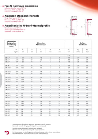
  • 1. Fers U normaux américains Inclinaison des ailes: environ 16 2/3 % Dimensions: ASTM A6/A6M - 02 Tolérances: ASTM A6/A6M - 02 American standard channels b Flange slope: approx. 16 2/3 % ss 45o Dimensions: ASTM A6/A6M - 02 Tolerances: ASTM A6/A6M - 02 ys ym Amerikanische U-Stahl-Normalprofile y h d y Flanschneigung: ca. 16 2/3 % Abmessungen: ASTM A6/A6M - 02 tw Toleranzen: ASTM A6/A6M - 02 tf z z Désignation Designation Dimensions Surface Bezeichnung Abmessungen Oberfläche (metric) G h b tw tf d A AL AG kg/m mm mm mm mm mm mm 2 m /m2 m2/t x 102 C 75 x 6.1* 6.1 76.2 35 4.3 6.9 38 7.81 0.277 45.47 C 75 x 7.4* 7.4 76.2 37 6.6 6.9 38 9.48 0.281 37.95 C 75 x 8.9* 8.9 76.2 40 9 6.9 38 11.30 0.288 32.35 C 100 x 8* 8.0 101.6 40 4.7 7.5 66 10.30 0.347 43.36 C 100 x 10.8* 10.8 101.6 43 8.2 7.5 60 13.70 0.352 32.55 C 130 x 10.4* 10.4 127 47 4.8 8.1 83 12.70 0.424 40.77 C 130 x 13* 13.0 127 48 8.3 8.1 86 17.00 0.422 31.47 C 150 x 12.2* 12.2 152.4 48 5.1 8.7 107 15.50 0.478 39.19 C 150 x 15.6* 15.6 152.4 51 8 8.7 107 19.90 0.484 31.05 C 150 x 19.3* 19.3 152.4 54 11.1 8.7 105 24.70 0.490 25.39 C 180 x 14.6* 14.6 177.8 53 5.3 9.3 130 18.50 0.548 37.51 C 180 x 18.2* 18.2 177.8 55 8 9.3 130 23.20 0.550 30.24 C 180 x 22* 22.0 177.8 58 10.6 9.3 125 27.90 0.557 25.30 C 200 x 17.1* 17.1 203 57 5.6 9.9 156 21.80 0.564 33.22 C 200 x 20.5* 20.5 203 59 7.7 9.9 156 26.10 0.577 28.82 C 200 x 27.9* 27.9 203 64 12.4 9.9 156 35.50 0.584 21.41 C 230 x 19.9* 19.9 228.6 61 5.9 10.5 177 25.40 0.679 34.11 C 230 x 22* 22.0 228.6 63 7.2 10.5 177 28.50 0.684 30.68 C 230 x 30* 30.0 228.6 67 11.4 10.5 173 37.90 0.692 23.20 C 250 x 22.8+ 22.8 254 65 6.1 11.1 203 29.00 0.692 30.85 C 250 x 30+ 30.0 254 69 9.6 11.1 203 37.90 0.701 23.98 C 250 x 37+ 37.0 254 73 13.4 11.1 203 47.40 0.713 19.52 C 250 x 45+ 45.0 254 76 17.1 11.1 203 56.90 0.721 16.58 * Tonnage minimum et conditions de livraison nécessitent un accord préalable. + Commande minimale: 40 t par profilé et qualité ou suivant accord. * Minimum tonnage and delivery conditions upon agreement. + Minimum order: 40 t per section and grade or upon agreement. * Die Mindestmengen pro Bestellung sowie die Lieferbedingungen sind im Voraus zu vereinbaren. 176 + Mindestbestellmenge: 40 t pro Profil und Güte oder nach Vereinbarung.
  • 2. Notations pages 211-215 / Bezeichnungen Seiten 211-215 Désignation Valeurs statiques / Section properties / Statische Kennwerte Classification C A572/A709/A992 Designation axe fort y-y axe faible z-z ENV 1993-1-1 Bezeichnung strong axis y-y weak axis z-z (imperial) pure pure starke Achse y-y schwache Achse z-z bending y-y compression G Iy Wel.y Wpl.y■ iy Avz Iz Wel.z Wpl.z’ iz ss It Iw ys ym S 235 S 355 S 235 S 355 4 3 3 2 4 3 3 4 6 lbs/ft mm mm mm mm mm mm mm mm mm mm mm mm mm mm x 104 x 103 x 103 x 10 x 102 x 104 x 103 x 103 x 10 x 104 x 109 x 10 x 10 C 3 x 4.1 4.1 69.11 18.14 21.7 2.98 3.78 7.96 3.27 6.40 1.01 18.2 1.31 0.07 1.06 1.99 1 1 1 1 ✔ C3x5 5.0 76.58 20.1 24.9 2.85 5.33 9.63 3.65 7.36 1.01 20.4 2.20 0.09 1.06 1.83 1 1 1 1 ✔ C3x6 6.0 86.37 22.67 28.7 2.76 7.00 12.1 4.19 8.80 1.03 23.2 4.14 0.11 1.13 1.76 1 1 1 1 ✔ C 4 x 5.4 5.4 160.3 31.56 37.8 3.97 5.14 13.8 4.89 9.40 1.16 18.4 1.67 0.22 1.15 2.21 1 1 1 1 ✔ C 4 x 7.2 7.2 190.8 37.56 47.0 3.72 8.59 17.4 5.48 11.3 1.12 23.2 4.25 0.30 1.13 1.90 1 1 1 1 ✔ C 5 x 6.7 6.7 332.4 52.34 61.8 5.01 6.81 24.3 7.19 14.1 1.36 21.2 2.72 0.62 1.29 2.53 1 1 1 1 ✔ C5x9 9.0 371.3 58.47 73.1 4.66 10.71 27.4 7.65 15.3 1.27 23.5 4.90 0.73 1.21 2.11 1 1 1 1 ✔ C 6 x 8.2 8.2 548.4 72.0 85.6 5.94 8.50 29.2 8.30 16.1 1.37 22.1 3.37 1.09 1.26 2.49 1 1 1 1 ✔ C 6 x 10.5 10.5 630.0 82.68 103 5.63 12.58 36.0 9.36 18.7 1.35 24.8 5.96 1.40 1.24 2.23 1 1 1 1 ✔ C 6 x 13 13.0 720.8 94.59 121 5.41 17.08 42.4 10.3 22.1 1.31 28.6 12.03 1.72 1.28 2.02 1 1 1 1 ✔ C 7 x 9.8 9.8 895.5 100.7 120 6.94 10.22 42.7 10.9 21.1 1.52 23.3 4.39 2.18 1.36 2.73 1 1 1 1 ✔ C 7 x 12.25 12.2 1007 113.3 140 6.59 14.71 49.2 11.8 23.4 1.46 25.9 7.25 2.62 1.31 2.41 1 1 1 1 ✔ C 7 x 14.75 14.7 1143 128.6 163 6.39 19.31 56.8 12.7 27.0 1.42 30.0 13.92 3.19 1.33 2.21 1 1 1 1 ✔ C 8 x 11.5 11.5 1340 132 156 7.86 13.23 53.8 12.6 27.6 1.57 29.3 5.86 3.79 1.44 3.19 1 1 1 2 ✔ C 8 x 13.7 13.7 1490 147 177 7.57 16.66 62.0 13.7 30.0 1.54 27.5 7.60 4.50 1.39 2.90 1 1 1 1 ✔ C 8 x 18.5 18.5 1820 179 226 7.15 26.00 81.7 16.4 35.9 1.51 30.6 17.87 6.00 1.43 2.51 1 1 1 1 ✔ C 9 x 13.4 13.4 1991 174.2 208 8.86 14.38 76.1 16.7 31.9 1.73 25.7 7.08 6.47 1.50 3.05 1 1 1 2 ✔ C 9 x 15 15.0 2132 186.5 226 8.66 17.18 85.3 17.8 34.3 1.73 26.9 8.80 7.39 1.49 2.93 1 1 1 1 ✔ C 9 x 20 20.0 2544 222.5 282 8.19 26.44 103 19.8 41.0 1.65 32.1 19.92 9.52 1.47 2.52 1 1 1 1 ✔ C 10 x 15.3 15.3 2770 218 257 9.81 17.62 91.2 18.5 40.3 1.78 32.0 9.15 10.40 1.58 3.55 1 1 2 3 ✔ C 10 x 20 20.0 3260 257 315 9.29 26.13 114 21.2 46.5 1.74 33.6 15.69 13.09 1.53 3.13 1 1 1 1 ✔ C 10 x 25 25.0 3790 298 377 8.93 35.17 138 24.0 52.6 1.70 34.4 28.58 16.17 1.56 2.80 1 1 1 1 ✔ C 10 x 30 30.0 4270 336 434 8.68 44.02 158 26.5 57.4 1.67 35.2 48.84 19.53 1.63 2.53 1 1 1 1 ✔ ■ Wpl.y est calculé selon l’hypothèse d’un diagramme de contraintes bi-rectangulaire et n’est applicable que si deux ou plusieurs fers U sont associés de façon à constituer une section doublement symétrique pour laquelle un moment de flexion agissant dans le plan du centre de gravité n’engendre pas de torsion. ■ Wpl.y is determined assuming a bi-rectangular stress block distribution. Thus, the given value applies only if two or more channels are combined in such a way to form a doubly symmetric cross-section so that the bending moment acting in the plane of the centre of gravity will not lead to torsion. ■ Für die Berechnung von Wpl.y wurde eine doppelrechteckige Spannungsverteilung angenommen. Der angegebene Wert ist daher nur anwendbar, wenn zwei oder mehr U-Profile so miteinander kombiniert sind, dass sie einen doppelsymmetrischen Querschnitt bilden, womit ein Biegemoment, das in 177 der Schwerpunktebene angreift, keine Torsion hervorruft.
  • 3. Fers U normaux américains (suite) Inclinaison des ailes: environ 16 2/3 % Dimensions: ASTM A6/A6M - 02 Tolérances: ASTM A6/A6M - 02 American standard channels (continued) b Flange slope: approx. 16 2/3 % ss 45o Dimensions: ASTM A6/A6M - 02 Tolerances: ASTM A6/A6M - 02 ys ym Amerikanische U-Stahl-Normalprofile (Fortsetzung) y h d y Flanschneigung: ca. 16 2/3 % Abmessungen: ASTM A6/A6M - 02 tw Toleranzen: ASTM A6/A6M - 02 tf z z Désignation Designation Dimensions Surface Bezeichnung Abmessungen Oberfläche (metric) G h b tw tf d A AL AG kg/m mm mm mm mm mm mm 2 m /m2 m2/t x 102 C 310 x 30.8+ 30.8 305 74 7.2 12.7 248 39.30 0.825 26.60 C 310 x 37+ 37.0 305 77 9.8 12.7 248 47.40 0.841 22.71 C 310 x 45+ 45.0 305 80 13 12.7 248 56.90 0.824 18.27 C 380 x 50.4+ 50.4 381 86 10.2 16.5 308 64.30 1.048 20.96 C 380 x 60+ 60.0 381 89 13.2 16.5 308 76.10 1.037 17.55 C 380 x 74+ 74.0 381 94 18.2 16.5 308 94.80 1.040 14.05 + Commande minimale: 40 t par profilé et qualité ou suivant accord. + Minimum order: 40 t per section and grade or upon agreement. 178 + Mindestbestellmenge: 40 t pro Profil und Güte oder nach Vereinbarung.
  • 4. Notations pages 211-215 / Bezeichnungen Seiten 211-215 Désignation Valeurs statiques / Section properties / Statische Kennwerte Classification C A572/A709/A992 Designation axe fort y-y axe faible z-z ENV 1993-1-1 Bezeichnung strong axis y-y weak axis z-z (imperial) pure pure starke Achse y-y schwache Achse z-z bending y-y compression G Iy Wel.y Wpl.y■ iy Avz Iz Wel.z Wpl.z iz ss It Iw ys ym S 235 S 355 S 235 S 355 4 3 3 2 4 3 3 4 6 lbs/ft mm mm mm mm mm mm mm mm mm mm mm mm mm mm x 104 x 103 x 103 x 10 x 102 x 104 x 103 x 103 x 10 x 104 x 109 x 10 x 10 C 12 x 20.7 20.7 5340 350 415 11.7 24.46 157 27.7 60.2 2.00 35.1 16.03 24.81 1.74 3.91 1 1 2 4 ✔ C 12 x 25 25.0 5970 391 477 11.2 31.26 183 30.5 66.0 1.97 33.5 21.91 29.49 1.70 3.58 1 1 1 1 ✔ C 12 x 30 30.0 6720 441 551 10.9 42.54 209 33.2 72.1 1.92 41.8 39.19 34.40 1.70 3.24 1 1 1 1 ✔ C 15 x 33.9 33.9 13100 688 825 14.3 38.72 334 50.5 107 2.28 32.1 38.26 83.39 1.99 4.24 1 1 1 2 ✔ C 15 x 40 40.0 14400 756 934 13.8 50.93 379 54.7 115 2.24 38.3 57.31 96.44 1.97 3.90 1 1 1 1 ✔ C 15 x 50 50.0 16700 877 1120 13.3 69.70 454 61.5 130 2.19 42.7 107.7 118.2 2.02 3.48 1 1 1 1 ✔ ■ Wpl.y est calculé selon l’hypothèse d’un diagramme de contraintes bi-rectangulaire et n’est applicable que si deux ou plusieurs fers U sont associés de façon à constituer une section doublement symétrique pour laquelle un moment de flexion agissant dans le plan du centre de gravité n’engendre pas de torsion. ■ Wpl.y is determined assuming a bi-rectangular stress block distribution. Thus, the given value applies only if two or more channels are combined in such a way to form a doubly symmetric cross-section so that the bending moment acting in the plane of the centre of gravity will not lead to torsion. ■ Für die Berechnung von Wpl.y wurde eine doppelrechteckige Spannungsverteilung angenommen. Der angegebene Wert ist daher nur anwendbar, wenn zwei oder mehr U-Profile so miteinander kombiniert sind, dass sie einen doppelsymmetrischen Querschnitt bilden, womit ein Biegemoment, das in 179 der Schwerpunktebene angreift, keine Torsion hervorruft.