Lecture 4 5 Urm Shear Walls
•
2 gefällt mir•4,398 views

Dan Abrams + Magenes Course on Masonry

Empfohlen
Weitere ähnliche Inhalte
Was ist angesagt?
Was ist angesagt? (20)
Andere mochten auch
Andere mochten auch (20)
Ähnlich wie Lecture 4 5 Urm Shear Walls
Mehr von Teja Ande
Mehr von Teja Ande (20)
Kürzlich hochgeladen
Kürzlich hochgeladen (20)
Lecture 4 5 Urm Shear Walls
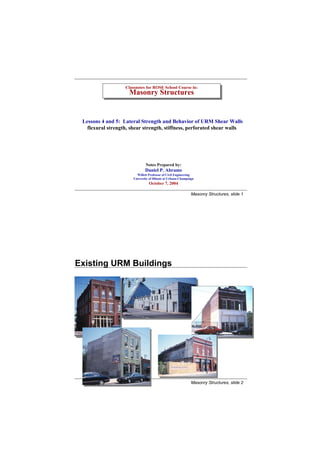
- 1. Classnotes for ROSE School Course in: Classnotes for ROSE School Course in: Masonry Structures Masonry Structures Lessons 4 and 5: Lateral Strength and Behavior of URM Shear Walls flexural strength, shear strength, stiffness, perforated shear walls Notes Prepared by: Daniel P. Abrams Willett Professor of Civil Engineering University of Illinois at Urbana-Champaign October 7, 2004 Masonry Structures, slide 1 Existing URM Buildings Masonry Structures, slide 2
- 2. Damage to Parapets 1996 Urbana Summer 1994 Northridge Earthquake, Filmore Masonry Structures, slide 3 Damage Can Be Selective 1886 Charleston, South Carolina Masonry Structures, slide 4
- 3. Damage to Corners 1994 Northridge Earthquake, LA Masonry Structures, slide 5 Damage to In-Plane Walls 1994 Northridge Earthquake, Hollywood URM cracked pier, Hollywood Masonry Structures, slide 6
- 4. Damage to Out-of-Plane Walls 1886 Charleston, South Carolina 1996 Yunnan Province Earthquake, Lijiang Masonry Structures, slide 7 Likely Consequences St. Louis Firehouse 1999 Armenia, Colombia Earthquake Masonry Structures, slide 8
- 5. 2001 Bhuj Earthquake Masonry Structures, slide 9 Lateral Strength of URM Shear Walls Masonry Structures, slide 10
- 6. URM Shear Walls P3 H3 n Pi Pb = ∑ Pi i =1 Hi n Vb = ∑ H i P1 i =1 H1 diagonal n hi tension crack M b = ∑ H i hi i=1 flexural flexural tension compression crack cracks Mb Vb Pb Ref: BIA Tech. Note 24C The Contemporary Bearing Wall - Introduction to Shear Wall Design NCMA TEK 14-7 Concrete Masonry Shear Walls Masonry Structures, slide 11 URM Shear Walls Design Criteria (a) allowable flexural tensile stress: -fa + fb < Ft Ft given in UBC 2107.3.5 (Table 21 - I); Ft = 0 per MSJC Sec. 2.2.3.2 pg. cc-35 of MSJC Commentary reads: Note, no values for allowable tensile stress are given in the Code for in-plane bending because flexural tension in walls should be carried by reinforcement for in-plane bending. (b) allowable axial and flexural compressive stress: fa fb MSJC Sec. 2.2.3.1 and UBC 2107.3.4 unity formula: + < 1.0 Fa Fb where: Fa = allowable axial compressive stress (UBC 2107.3.2 or MSJC 2.2.3) Fb = allowable flexural compressive stress = 0.33 f´m (UBC 2107.3.3 or MSJC 2.2.3) Masonry Structures, slide 12
- 7. Allowable Tensile Stresses, Ft MSJC Table 2.2.3.2 and UBC Table 21-I Mortar Type Direction of Tension and Portland Cement/Lime or Mortar Cement Masonry Cement/Lime Type of Masonry all units are (psi) M or S N M or S N tension normal to bed joints solid units 40 30 24 15 hollow units 25 19 15 9 fully grouted units 68* 58* 41* 26* tension parallel to bed joints solid units 80 60 48 30 hollow units 50 38 30 19 fully grouted units 80* 60* 48* 29* * grouted masonry is addressed only by MSJC Masonry Structures, slide 13 URM Shear Walls Design Criteria (c) allowable shear stresses: UBC Sec. 2107.3.7 shear stress, unreinforced masonry: clay units: Fv = 0.3 (f’m)1/2 < 80 psi (7-44) concrete units: with M or S mortar Fv = 34 psi with N mortar Fv = 23 psi allowable shear stress may be increased by 0.2 fmd where fmd is compressive stress due to dead load V Per UBC Sec. 2107.3.12 shear stress is average shear stress, fv = Ae Masonry Structures, slide 14
- 8. URM Shear Walls Design Criteria (c) allowable shear stresses: MSJC Sec. 2.2.5.2: shear stress, unreinforced masonry: Fv shall not exceed the lesser of: (a) 1.5 (f’m)1/2 (b) 120 psi (c) v + 0.45 Nv/An where v = 37 psi for running bond, w/o solid grout 37 psi for stack bond and solid grout 60 psi for running bond and solid grout (d) 15 psi for masonry in other than running bond VQ Note: Per MSJC Sec. 2.2.5.1, shear stress is maximum stress, f v = Ib Masonry Structures, slide 15 URM Shear Walls Design Criteria (c) allowable shear stresses: fvmax V 2 f v avg = = fv Anet 3 max fvavg 3 V f v max = 2 Anet for rectangular section Masonry Structures, slide 16
- 9. URM Shear Walls Possible shear cracking modes. strong mortar low vertical weak mortar weak units compressive stress strong units through masonry units sliding along bed joints stair step through bed and head joints Associated NCMA TEK Note #66A: Design for Shear Resistance of Concrete Masonry Walls (1982) Masonry Structures, slide 17 Example: URM Shear Walls Determine the maximum base shear per UBC and MSJC. 5000 lb. DL 8” CMU’s with face shell bedding H block strength = 2800 psi Type N Portland cement lime mortar special inspection provided during construction 9’- 4” Net section with face shell bedding: H 80” 1.25” 9’- 4” Anet = 2.5 (80) = 200 in 2 S net = 2.5 (80)2 / 6 = 2667 in 3 h' r = 2.84quot; h’ = 112quot; = 39.4 6’ - 8” r Masonry Structures, slide 18
- 10. Example Forces and Stresses: Vb = 2 H M b = Vb (1.5 x 9.33 ) x 12 = 168 Vb f a dead = 2 (5000 lbs) / 200 in 2 = 50 psi (neglectin g self weight) f b = M/S = 168 Vb /2667 = 0.0630 Vb Maximum base shear capacity per UBC shear stress Fv = 23 + 0.2 f md = 23 + 0.2 (50) = 33 psi (Sec. 2107.3.7) Vmax = (33 psi x 1.33) (200 in 2 ) = 7980 lbs. (does not govern) flexural tensile stress Ft = 19 psi x 1.33 = 25.3 psi (Ft per Sec. 2107.3.5 ) - f a + f b = Ft - 50 + 0.0630Vb = 25.3 V b = 1194 lbs. (governs) Masonry Structures, slide 19 Example Maximum base shear capacity per UBC flexural compressive stress fa fb h 2 h' + < 1.33 Fa = 0.25f´ m [1 - ( ) ] = 0.23 f´ m for ≤ 99 Fa Fb 140r r f´ m = 1850 psi per Table 21 - D for f´ u = 2800 psi and Type N mortar Fa = 426 psi Fb = 0.33 (1850) = 616 psi 50 0 .0630 Vb + = 1.33 Vb = 11,857 lbs. (does not govern) 426 616 Maximum base shear capacity per MSJC In lieu of prism tests, a lower bound compressive strength of 1861 psi will be used based on the 2800 psi unit strength and Type N mortar per MSJC Spec. Table 2. shear stress Fv = 1.5 (f´ m )1/2 = 1.5 (1861)1/2 = 65 psi or Fv = 37 psi + 0.45 (50 psi) = 60 psi (governs) 2 2 Vmax = Fv Anet = (60 psi x 1.33) (200 in 2 ) 3 3 = 10,629 lbs. (does not govern) Masonry Structures, slide 20
- 11. Example Maximum base shear capacity per MSJC flexural tensile stress per MSJC Sec. 2.2.3.2 : Ft = 0 psi - fa + fb = 0 - 50 + 0.0630 Vb = 0 V b = 794 lbs. (governs) flexural compressive stress fa fb Fa = 0.25f´ m [1 - (h/140r) 2 ] = 0.23 f´ m = 426 psi for h/r = 39.4 + < 1.33 Fa Fb Fb = 0.33 (1861) = 620 psi 50 0.0630 Vb + = 1.33 Vb = 11,934 lbs. (does not govern) 426 620 Summary: Vb max axial and flexural stress shear stress tension compression UBC 7890 1194 11,857 MSJC 10,629 794 11,934 Masonry Structures, slide 21 URM Shear Walls Post-Cracked Behavior σ v = fa P =σvA Hh H equilibrium : Hh = Pe ; e = P 2P [1] fm = = compressive edge stress ≤ Fa or Fb bη h η L ⎛L ⎞ = −e η = 3⎜ − e ⎟ [2] 3 2 ⎝2 ⎠ toe combining above equations : heel 2P 2P 1 fm< Fa fm = = bη ⎛L ⎞ L2 [3] 3b⎜ − e ⎟ P ⎝2 ⎠ L2 width = b η e 3 4P L/2 fm = ⎛ e ⎞ η 3 bL ⎜ 1 - 2 ⎟ ⎝ L⎠ Masonry Structures, slide 22
- 12. URM Shear Walls Post-Cracked Behavior Lateral Load, H resultant load, P, shifts toward toe toe crushing cracking load 2 to 3 times first flexural cracking MSJC/UBC assumed behavior Lateral Deflection at Top of Wall Note: shear strength should be checked considering effects of flexural cracking Masonry Structures, slide 23 Perforated URM Shear Walls Masonry Structures, slide 24
- 13. Lateral Stiffness of Shear Walls Cantilevered shear wall flexure shear : ∆ Hh 3 H 1 ∆= + h 3E m I Av G H common assumption s : Av = 5/6 Ag G = 0.4 E m Hh 3 1.2 Hh ∆= + 3E m I Ag (0.4 E m ) bL3 Ig = 12 h 4 Hh 3 3 Hh Ag = bL ∆= + E m bL3 bLE m H ⎛ h ⎞⎡ ⎛ h ⎞ ⎤ 2 ∆= ⎜ ⎟ ⎢4⎜ ⎟ + 3⎥ bE m ⎝ L ⎠ ⎢ ⎝ L ⎠ ⎣ ⎥ ⎦ bE m k = lateral stiffness = H/∆ = L ⎛ h⎞ ⎡ ⎛ h ⎞2 ⎤ ⎜ ⎟ ⎢4⎜ ⎟ + 3⎥ L ⎠⎣ ⎝ L ⎠ ⎝ ⎢ ⎥ ⎦ Masonry Structures, slide 25 Lateral Stiffness of Shear Walls Pier between openings flexure shear 3 Hh H 1 ∆= + h H 12E m I Av G Hh 3 1.2 Hh ∆= + E m bL3 bL(0.4 E m ) h H ⎛ h ⎞ ⎡⎛ h ⎞ ⎤ 2 ∆= ⎜ ⎟ ⎢⎜ ⎟ + 3 ⎥ bE m ⎝ L ⎠ ⎢⎝ L ⎠ ⎣ ⎥ ⎦ H L bE m k = lateral stiffness = H / ∆= ⎛ h ⎞ ⎡⎛ h ⎞ ⎤ 2 ⎜ ⎟ ⎢⎜ ⎟ + 3⎥ ⎝ L ⎠ ⎢⎝ L ⎠ ⎣ ⎥ ⎦ Masonry Structures, slide 26
- 14. Lateral Stiffness of Shear Walls k 1.6 bE m 1.4 cantilever 1 1.2 k= ⎛ h ⎞⎡ ⎛ h ⎞ ⎤ 2 ⎜ ⎟⎢ 4 ⎜ ⎟ + 3⎥ 1.0 ⎝ L ⎠⎢ ⎝ L ⎠ ⎣ ⎥ ⎦ 0.8 fixed pier 1 0.6 k= ⎛ h ⎞ ⎡⎛ h ⎞ ⎤ 2 ⎜ ⎟ ⎢⎜ ⎟ + 3 ⎥ 0.4 ⎝ L ⎠ ⎢⎝ L ⎠ ⎣ ⎥ ⎦ 0.2 h 0 0.2 0.4 0.6 0.8 1.0 1.2 1.4 1.6 1.8 2.0 L Masonry Structures, slide 27 References Associated NCMA TEK Note: 61A Concrete Masonry Load Bearing Walls - Lateral Load Distribution (1981) Associated BIA Technical Note: 24C The Contemporary Bearing Wall - Introduction to Shear Wall Design 24D The Contemporary Bearing Wall - Example of Shear Wall Design 24I Earthquake Analysis of Engineered Brick Masonry Structures Masonry Structures, slide 28
- 15. Example: Lateral-Force Distribution Determine the distribution of the lateral force, H, to walls A, B and C. A B C H 10’-0” 18’-0” 6’-0” type of masonry and wall thickness is the same for each wall h=15’ wall L h/L ki * ki / ∑ ki *based on cantilever action bEm A 10’ 1.50 0.0556 bEm 0.20 ki = h ⎞⎡ ⎛ h ⎞ ⎤ 2 ⎛ B 18’ 0.83 0.2077 bEm 0.75 ⎜ ⎟ ⎢ 4 ⎜ ⎟ + 3⎥ ⎝ L ⎠⎢ ⎝ L ⎠ ⎣ ⎥ ⎦ C 6’ 2.50 0.0143 bEm 0.05 Σki = 0.2776 bEm Masonry Structures, slide 29 Lateral-Force Distribution to Piers Perforated Shear Walls equilibrium: H = V1 + V2 + V3 ∆ overall story stiffness: H H H V3 H = K∆ or ∆ = = K ∑ ki V1 V2 where K = lateral story stiffness h3 = ∑ k i = k1 + k 2 + k 3 h2 h1 bi Emi ki = for fixed − fixed pier ⎛ hi ⎞ ⎡⎛ hi ⎞ ⎤ 2 L2 ⎜ ⎟ ⎢⎜ ⎟ + 3 ⎥ ⎜L ⎟ ⎜L ⎟ L1 L2 L3 ⎝ i ⎠ ⎢⎝ i ⎠ ⎣ ⎥ ⎦ shear force attracted to single pier: Vi = k i ∆i = k i ∆ = k i Η / ∑ k i Vi = (k i / ∑ k i ) Η k i / ∑ k i = distributi on factor Masonry Structures, slide 30
- 16. Example: Lateral Force Distribution to Piers Determine the distribution of story shear, H, to each pier. 40” 40” 32” 8”grouted H concrete block 24” Va Vb Vc 112” 64” A A 24” Elevation 7.63” 56” a b c Section A-A Masonry Structures, slide 31 Example: Lateral Force Distribution to Piers 7.63 x48 = 366 x 7.63/2 = 1397 7501 piers a and c 7.63 x 40 = 305 x 20 = 6104 y= = 11.2quot; 671 7.63” 671 7501 I gross= 366(11.2 3.81) + 305(20− 11.2) + 7.63(40.0) /12= 84,273 4 − 2 2 3 in y Av = (5/6) Aweb = (5/6) (7.63quot; )(40.0) = 254 in 2 48” 1 1 7.63” ka = k c = = = 1.12 E h3 h ( 64 )3 64 + + 12EI GAv 12E(84,273) ( 0.4 E )( 254 ) 40” bEm 7.63 E kb = = = 1.91 E h ⎞ ⎡⎛ h ⎞ ⎤ 1 [1 + 3] 2 ⎛ ⎜ ⎟ ⎢⎜ ⎟ + 3 ⎥ pier b ⎝ L ⎠ ⎢⎝ L ⎠ ⎣ ⎥ ⎦ ∑ ki = ( 1.12 + 1.91 + 1.12 ) Ε = 4.16 Ε 7.63” 64” DFa = DFc = 1 .12 / 4 .16 = 0 .27 DFb = 1 .91 / 4 .16 = 0 .46 Masonry Structures, slide 32
- 17. Perforated Shear Walls Axial Force due to Overturning equilibrium of pier axial forces: ∑ pi = 0 for zero gravity force [1] ∑ pi = 0 = ∑ f ai Ai [2] ∑ Ai ≠ 0 thus, centroid of pier [3] areas = neutral axis y= ∑ Ai yi [4] ∑ Ai equilibrium of moments: M = ∑ pi yi = ∑ f ai Ai yi [5] y1 y2 from similar triangles: y3 f ai = f max y i / c [6] y1 y2 y3 y substituting in [5]: fai= ave. axial ⎛ y ⎞ [7] fmax M = ∑ ⎜ f max i ⎟ Ai yi p2 p3 stress across ⎝ c ⎠ p1 pier “i” f max f c M M= c ∑ Ai yi 2 M = max I c [8] Masonry Structures, slide 33 Perforated Shear Walls Axial Force due to Overturning solving for fmax: Mc f max = [10] I substituting in [6]: ⎛ Mc ⎞ yi Myi f ai = ⎜ ⎟ = [11] ⎝ I ⎠c I MAi yi pi = Ai f i = I [12] Ai yi pi = M [13] ∑ Ai yi2 distribution factor for overturning moment Masonry Structures, slide 34
- 18. Perforated Shear Walls Design Criteria for Piers between Openings flexure: unreinforced piers P fa f b compressio n + < 1.0 Fa Fb M V tension - f a + f b < Ft flexure: reinforced piers h neglecting axial force : 2M compressio n f b = < Fb V jkbd 2 M=Vih/2 M tension f s = < Fs As jd P P = Pdead + Plive + Plateral considering axial force : (a) unity equation (UBC only) (b) load - moment interaction diagram P (c) modify As by (only when tension controls) bdFs Masonry Structures, slide 35 Perforated Shear Walls Design Criteria for Piers between Openings P shear: unreinforced piers VQ M MSJC fv = < Fv I net b V V UBC fv = < Fv Ae h shear: reinforced piers V V UBC fv = < Fv M=Vih/2 bjd V P MSJC fv = < Fv bd Loading Combinations UBC MSJC Sec. 2.1.1 Effect D+L D+L Pmax for small lateral load 0.75(D+L+W/E) D+L+W/E Pmax and Mmax for large lateral 0.9D-0.75E 0.9D+E Pmin for smallest moment capacity D+W Masonry Structures, slide 36
- 19. Example: Perforated Shear Wall Check stress per the UBC for the structure shown below. Design pier reinforcement if necessary. 14.9 kip Special inspection is provided 10’-0” Earthquake f’m = 2500 psi Loads fully grouted but unreinforced 14.9 kip Grade 60 reinforcement Type N mortar with Portland Cement 10’-0” 7.4 kip Gravity Loads Level Dead Live 9’-8” 3 50 kip 80 kip 2 60 kip 80 kip 1 60 kip 80 kip 18’-8” total 170 kip 240 kip Masonry Structures, slide 37 Example: Perforated Shear Wall Pier Dimensions 18’-8” 3’-4” 5’-4” 3’-4” 3’-4” 3’-4” 2’-8” 4’-0” 2’-8” 8” grouted 9’-4” concrete block 7.63” 3’-4” a b c 40” 32” Masonry Structures, slide 38
- 20. Example: Perforated Shear Wall Stiffness of Pier “a” y = [32 (7.63)2 / 2 + 7.63 (40 2 /2)] / 549 = 12.82quot; a I g = (7.63)3 (32)/12 + 7.63(32)(12.82 - 7.63/2)2 7.63” + 7.63(40)3 /12 + 7.63(40)(20 - 12.82)2 = 76 ,470 in 4 7.63” 32” 1 ka = 3 h h y + 12Em I (5/6 Aweb )(0.4 E m ) 40” 1 ka = 3 48 48 + 12Em 76 ,740 (5/6 × 7.63 × 40)(0.4 E m ) 1 ka = = 1.69 E m 0.120 0.472 + Em Em Masonry Structures, slide 39 Example: Perforated Shear Wall Stiffness of Pier “b” Ig =7.63 (40) 3 / 12=40,693 in4 7.63” b 1 kb = h3 h + 40” 12E m I (5/6 Aweb )(0.4 E m ) 1 kb = 48 3 48 + 12E m 40 ,693 (5/6 × 7.63 × 40)(0.4 E m ) 1 kb = = 1.43 Em 0.226 0.472 + Em Em Masonry Structures, slide 40
- 21. Example: Perforated Shear Wall Stiffness of Pier “c” 1 kc = h3 h + 32” c 12E m I (5/6 Aweb )(0.4 E m ) 1 kc = 112 3 7.63” 112 40” + 12E m 76 ,470 (5/6 × 7.63 × 40)(0.4 E m ) 1 I g = 76 ,470 in 4 kc = = 0.38 E m 1.526 1.101 (same as Pier a) + Em Em Distribution of Story Shear to Piers Vbase = 14.9 k + 14.9 k + 7.4 k = 37.2 k pier ki DF i Vi a 1.69 Em 0.483 18.0 b 1.43 Em 0.409 15.2 c 0.38 Em 0.109 4.0 Σ k = 3.50 Em 1.000 37.2 k Masonry Structures, slide 41 Example: Perforated Shear Wall Distribute Overturning Moments to Piers y 7.63” 40.0” a b c 124.0” 12.82” 211.2” y 2 = 9 . 38 quot; y 1 = 101 .8quot; y 3 = 96 .58 quot; pier Ai yi Aiyi a 549 12.8” 7038 b 305 124.0” 37,820 c 549 211.2” 115,949 ∑ Ai =1403 ∑ Aiyi=160,807 y = 160 ,807 / 1403 = 114.6quot; Masonry Structures, slide 42
- 22. Example: Perforated Shear Wall Distribute Overturning Moments to Piers total story moment = M1 (@top of window opening, first story) = 14.9k x 23.0’ + 14.9k x 13.0’ + 7.4k x 3.0’ = 558k-ft 2 Ai yi pier Ai y Ai y i I A i y i2 + I Ai yi Pi = M1 In (in2) (in) (1000 in4) (1000 in4) (1000 in4) (1000 in3) (kips) a 549 101.8” 5689 76 5765 55.9 33.9 b 305 -9.38 27 41 68 -2.9 -1.8 c 549 -96.58” 5120 76 5196 -53.0 -32.1 ∑A y 2 ∑ Ai = 1403 i i + I = 11,029 Masonry Structures, slide 43 Example: Perforated Shear Wall Summary of Pier Forces pier % gravity* Pd Pl Peq Veq Meq=Veq(h/2) (kips) (kips) (kips) (kips) (kip-in) a 0.361 61.4 86.6 33.9 18.0 432 b 0.319 54.2 76.6 -1.8 15.2 365 c 0.319 54.2 76.6 -32.1 4.0 224 *based on tributary wall length: pier a: (32” + 40” + 32”)/288 = 0.361 (assuming that floor loads are pier b: (32” + 40” + 20”)/288 = 0.319 applied uniformly to all walls) pier c: (20” + 40” + 32”)/288 = 0.319 Masonry Structures, slide 44
- 23. Example: Perforated Shear Wall Loading Combinations axial compressive force, P moment, M shear, V d case 1 case 2 case 3 pier D+L 0.75(D+L+E) 0.9D-0.75E 0.75Meq 0.75Veqx1.5* (kips) (kips) (kips) (kip-in) (kips) (in.) a 148.0 136.4 29.8 327 20.3 36 b 130.8 99.5 47.4 274 17.1 36 c 130.8 122.2 24.7 168 4.5 36 *UBC 2107.1.7 for Seismic Zones 3 and 4 Masonry Structures, slide 45 Example: Perforated Shear Wall Axial and Flexural Stresses, Load Case 1 = D + L a b c y y pier PD+L fa Fa* fa/Fa (kips) (psi) (psi) a 148.0 270 543 0.497 < 1.0 ok b 130.8 430 543 0.792< 1.0 ok c 130.8 239 543 0.440< 1.0 ok *Fa = 0.25f’m[1-(h/140r)2] r = 0.289t = 0.289 × 7.63 = 2.2quot; h = 9' −4quot; = 112quot; Note that conservative assumption is used for Fa calculation, r is the lowest and h is the full height. Masonry Structures, slide 46
- 24. Example: Perforated Shear Wall Axial and Flexural Stresses, Load Case 2: 0.75 (D + L + E) a b c y y pier 0.75(PD+L+EQ) fa=P/A Fa fa/Fa 0.75Me Sg fb fb/Fb** fa/Fa+fb /Fb (kips) (psi) (psi) (kip-in) (in3) (psi) a 136.4 249 543 0.459 327 2813* 116 0.139 0.598 < 1.0 ok b 99.5 326 543 0.600 274 2035 135 0.162 0.762 < 1.0 ok c 122.2 223 543 0.411 168 2813* 60 0.072 0.483 < 1.0 ok * minimum Sg is taken to give maximum fb for either direction of building sway ** Fb= 0.33f’m = 833 psi Masonry Structures, slide 47 Example: Perforated Shear Wall Axial and Flexural Stresses, Load Case 3: 0.9D - 0.75Peq a b c y y minimum axial compression: check tensile stress with Ft = 30 UBC Sec 2107.3.5 pier (0.9PD-0.75PEQ) fa=P/A 0.75Meq Sg fb - fa+fb (kips) (psi) (kip-in) (in3) (psi) (psi)** a 29.8 54 327 2813* 116 62 > 30 psi provide reinf. b 47.4 155 274 2035 135 -20 < 30 psi ok c 24.7 45 168 2813* 60 15 < 30 psi ok * minimum Sg is taken to give maximum fb for either direction of building sway **tensile stresses Masonry Structures, slide 48
- 25. Example: Perforated Shear Wall Pier Shear Stress, Load Case 4 : 0.75E a b c y y pier V=0.75Veq x 1.5 fv = V/Aweb fao = P/A* Fv = 23 + 0.2fao** (kips) (psi) (psi) (psi) a 20.3 67 54 34 < 67 provide shear reinf. b 17.1 56 155 54 < 56 provide shear reinf. c 4.5 15 45 32 > 15 ok * from Case 3 0.9Pd-0.75Peq ** UBC 2107.3.7 Masonry Structures, slide 49 Case Study: Large-Scale Test Masonry Structures, slide 50
- 26. Georgia Tech Large-Scale Test 24’ photo from Roberto Leon Masonry Structures, slide 51 Final Crack Pattern Load Direction slide from Roberto Leon Masonry Structures, slide 52
- 27. Final Crack Pattern Load Direction slide from Roberto Leon Masonry Structures, slide 53 Results- Global Behavior 80 Wall 1 Force-Displacement Response 60 40 Base Shear (kip) 20 0 -0.30 -0.20 -0.10 0.00 0.10 0.20 0.30 -20 -40 -60 -80 Roof Displacement (in) Masonry Structures, slide 54
- 28. Overturning Effect (Vertical Stress) Base strains recorded during loading in the push and pull direction slide from Roberto Leon Masonry Structures, slide 55 USA CERL Shaking Table Tests 12’ photos from S. Sweeney Masonry Structures, slide 56
- 29. Damage on North Wall Final Cracking Pattern Permanent offsets of 0.25” – 0.35” due to rocking of pier. slide from S. Sweeney Masonry Structures, slide 57 Peak Force vs. Deflection North-South Uni-directional Motion 30 Base Shear (kip) 25 20 PGA = 0.33 g PGA = 0.75 g 15 PGA = 0.98 g 10 PGA = 1.08 g 5 0 0 0.025 0.05 0.075 0.1 0.125 0.15 0.175 Average First Floor Deflection (in) East-West Uni-directional Motion 25 Base Shear (kip) 20 PGA = 0.30 g 15 PGA = 0.75 g 10 PGA = 1.09 g 5 PGA = 1.40 g 0 0 0.1 0.2 0.3 0.4 0.5 0.6 Average First Floor Deflection (in) slide from S. Sweeney Masonry Structures, slide 58
- 30. End of Lessons 4 & 5 Masonry Structures, slide 59