Optical recording system
•
0 gefällt mir•31 views

DISC,Processing of audio signal,Reconstitution of the audio signal,Video disk formats,Video recording system,Play back system,Readout from the disc

Empfohlen
Weitere ähnliche Inhalte
Was ist angesagt?
Ähnlich wie Optical recording system
Ähnlich wie Optical recording system (20)
Mehr von Tamilarasan N
Mehr von Tamilarasan N (15)
Kürzlich hochgeladen
Kürzlich hochgeladen (20)
Optical recording system
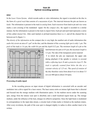
- 1. Unit III Optical recording system DISC In the Laser Vision System, which records audio or video information, the signal is recorded on the disc in the form of a spiral track that consists of a succession of pits. The intervals between the pits are known as lands. The information is present in the track in analog form. Each transition from land to pit and vice versa marks a zero crossing of the modulated signal. On the compact disc, the signal is recorded in a similar manner, but the information is present in the track in digital form. Each pit and each land represents a series of bits called channel bits. After each land/pit or pit/land transition there is a 1, and all the channel bits in between are 0, (figure 1 ). The density of the information on the compact disc is very high; the smallest unit of audio information (the audio hit) covers an area of 1 µm2 on the disc, and the diameter of the scanning light spot is only 1 µm. The pitch of the track is 1.6 µm, the width 0.6 µm and the depth 0.12 µm. The minimum length of a pit or the land between two pits is 0.9 µm; the maximum length is 3.3 µm. The side of the transparent carrier material T in which the pits are impressed, the upper side during playback if the spindle is vertical, is covered with a reflecting layer R and a protective layer P. The track is optically scanned from below the disc at a constant velocity of 1.25 m/s. The speed of rotation of the disc therefore varies from about 8 rev/s to about 3.5 revs (or 480 rpm to about 210 rpm). Processing of audio signal In the recording process an input stream of digital information is converted with an encoder and modulator into a drive signal for a laser source. The laser source emits an intense light beam that is directed and focused into the storage medium with illumination optics. As the medium moves under the scanning spot, energy from the intense scan spot is absorbed, and a small localized region heats up. The storage medium, under the influence of the heat, changes its reflective properties. Since the light beam is modulated in correspondence to the input data stream, a circular track of data marks is formed as the medium rotates. After every revolution, the path of the scan spot is changed slightly in radius to allow another track to be written.
- 2. For converting the analog signal from the microphone into a digital signal, pulse-code modulation (PCM) is used. In this system the signal is periodically sampled and each sample is translated into a binary number. From Nyquist’s sampling theorem the frequency of the sampling should be at least twice as high as the highest frequency to be accounted for in the analog signal. The number of bits per sample determines the signal-to- noise ratio in the subsequent reproduction. In the compact disc system the analog system is sampled at a rate of 44.1 kHz, which is sufficient for the reproduction of the maximum frequency of 20 kHz. The signal is quantized by the method of uniform or linear quantization, the sampled amplitude is divided into equal parts. The number of bits per sample (these are called audio bits) is 32 i.e. 16 for the left and 16 for the right audio channel. This corresponds to a signal- to-noise ratio of more than 90 dB. The net bit rate is thus 44.1 * 103 * 32 or 1.41 * 106 audio bits per second. The audio bits are grouped into frames, each containing six of the original samples Successive blocks of audio bits have blocks of parity bits added to them in accordance with a coding System called Cross-Interleaved Reed-Solomon Code (CIRC). This Makes it possible to correct errors during the reproduction of the signal. The ratio of the number of bits before and after this operation is 3 :4. Each frame then has Control and Display (C & D) bits added to it; one of the functions of C & D bits is providing the information for the listener, after this operation the bits are called data bits. Next, the bit stream is modulated, that is to say the data bits are translated into channel bits which are suitable for storage on the disc. The Eight-to- Fourteen Modulation (EFM) is used for this purpose. In EFM code blocks of eight bits are translated into blocks of fourteen bits. The blocks of fourteen bits are linked by these margin bits. The ratio of the number
- 3. of bits before and after modulation is thus 8:17. For the synchronization of the bit stream an identical synchronization pattern consisting of 27. Reconstitution of the audio signal The demodulation information is temporarily stored in a buffer memory and then reaches the Error-Detection and Correction Circuit (ERCO). The parity bits can be used here to correct errors, or just to detect errors if correction is found to be impossible. These errors may originate from a defect in manufacturing process, damage during use, or finger marks or dust on the disc. Since the information with the CIRC code is interleaved in time, errors that occur at the input of ERCO in one frame are spread over a large number of frames during decoding in ERCO. This increases the probability that the maximum number of correctable errors per frame will not be exceeded. A flaw, such as a scratch, can often produce a train of errors called an error burst. The error-correction code used in ERCO can correct a burst of about 4000 data bits, largely because the errors are spread out in this way. If more errors than the permitted maximum occur, they can only be detected. In the Concealment, Interpolation and Muting (CIM) block, the errors detected are then masked. If the value of a sample indicates an error, a new value is found by linear interpolation between the preceding value and the next one. If two or more successive sample values indicate an error, they are muted (made equal to zero). In the digital-to-analog convener (DAC) the 16 bit samples first pass through interpolation filters F and are then translated and recombined to re-create the original analog signal A from the two audio channels L and R. Since samples must be recombined at exactly the same rate as they are taken from the analog audio signal, the DACs and also CIM and ERCO are synchronized by a clock generator, C, controlled by a quartz crystal. Figure also illustrates the control of the disc speed nD. The bit stream leaves the buffer memory at a rate synchronized by the clock generator. The bit stream enters the buffer memory, however, at a rate that depends on the speed of revolution of the disc
- 4. Video disk formats The three non-interchangeable video disc formats fall into two basic categories optical and capacitance The laser optical system (also called VLP) which is employed by Philips, uses a laser beam to electronically encoded information stored on the disc. The capacitance system (also called capacitance electronic disc or CED), employed by both JVC and RCA, uses a stylus arid tracking arm similar to that of conventional record player to recover the information recorded on the grooves of the disc. There are two variations of the laser optical system reflective and transmissive. There are also two variations of capacitance system, the video/ audio high density system (VHD) and the capacitance electronic disc system (CED). In the above diagram upper half of this diagram shows the tracks of pits, while the lower half shows a cross-section of the disc indicating how the information pits are protected by a transparent protective coating Video recording system In the optical video disc there is a single information track in which all the information is stored for the reproduction of a colour television program with two sound channels and data signals. The nonlinearity of the master recording process limits the choice of possible encoding. Technique and a two-level signal recording was found to be the most attractive solution. On this track the information is enclosed in the length and the spacing of the pits or, in other words, for a routing disc in the repetition frequency, determined by the average length of the pits, and a pulse width modulation of the frequency
- 5. determined by the modulation of the length of the pits. The composite video signal employed in the video disc system is frequency modulated on a carrier at 8MHz which is pulse width modulated by two hi-fi audio channels at 2.3 MHz and 2.8 MHz. Figure.3.15 shows the block diagram of the signal processing for coding the video and audio system. Before FM modulation of the video signal pre-emphasis time constant of 50μs and 12.5 μs are employed. The audio signal are FM modulated on carrier of 2.3MHz and 2.8 MHz with a frequency deviation of +100KHz and a pre-emphasis of 75 μs. The two audio carriers are summed with the FM carrier and after limiting, the output signal is used to modulate the intensity of a laser beam passing through an electrode optical modulator in the master recording machine. Play back system Reading back the information, the reflected light returning from the disc falls on a photodiode and its output is amplified and corrected according to the frequency characteristic of the player. A high-pass filter separates the video information and the filters have a crossover frequency at 3.5 MHz. The separated FM signals are then demodulated and a de-emphasis is applied to compensate for the pre-emphasis employed more recording, in order to achieve a better S/N ratio and a more uniform frequency response.
- 6. Readout from the disc The disc is optically scanned in the player. This is done by AlGaAs semiconductor laser fig shows the optical part of the pickup. The light from the laser La (wavelength 800 nm) is focused through the lenses L2 and L1 onto the reflecting layer of the disc. The diameter of the light spot S, is about 1 μm. When the light falls on an interval between two pits, the light is almost totally reflected and reaches the four photodiodes D1 to D4 via the half-silvered mirror M. When the spot lands on a pit— the depth of a pit is about ¼ of the wavelength in the transparent substrate material—interference causes less light to be reflected and an appreciably smaller amount reaches the photodiodes. When the output signals from the four photodiodes are added together the result is a fairly rough approximation to the rectangular pulse pattern present on the disc in the form of pits and intervals. Diagram of the optical pick-up. D, radial section through the disc. S laser spot, the image of the disc of light emitting part of the semiconductor laser La. L1, objective lens, adjustable for focusing, L2 lens for making the divergent laser beam parallel. M half silvered mirror formed by a film evaporated on the dividing surface of the prism combination. P1,P2 be beam splitter prisms, D1 to D4 photodiodes whose output currents can be combined in various ways to provide the output signal from the pick op and also the tracking error signal and the focusing –error signal.