SunMaxx Datasheet Submittal - XMaxx Solar Hot Water Balancing Valves
•
0 gefällt mir•583 views

SunMaxx Datasheet Submittal - XMaxx Solar Hot Water Balancing Valves

Empfohlen
Empfohlen
Weitere ähnliche Inhalte
Was ist angesagt?
Was ist angesagt? (20)
Andere mochten auch
Andere mochten auch (20)
Ähnlich wie SunMaxx Datasheet Submittal - XMaxx Solar Hot Water Balancing Valves
Ähnlich wie SunMaxx Datasheet Submittal - XMaxx Solar Hot Water Balancing Valves (20)
Mehr von SunMaxx Solar
Mehr von SunMaxx Solar (9)
Kürzlich hochgeladen
Kürzlich hochgeladen (20)
SunMaxx Datasheet Submittal - XMaxx Solar Hot Water Balancing Valves
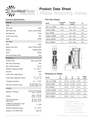
- 1. Product Data Sheet XMaxx Balancing Valves Specifications subject to change without noticeCopyright 2015 SunMaxx Solar | All Rights Reserved SunMaxx Solar 5042 - 5160 NY 206 Bainbridge, NY 13733 P: 1.877.786.6299 F: 1.800.786.0329 www.SunMaxxSolar.com Model Connection (NPT) Flow Rate (GPM) Cv .5IN-.5/1.75GPM 1/2” 1/2 - 1 3/4 1.0 .75IN-2/7GPM 3/4” 2.0 - 7.0 6.3 1IN-3/10GPM 1” 3.0 - 10.0 8.3 1.25IN-5/19GPM 1 1/4” 5.0 - 19.0 15.2 1.5IN-8/32GPM 1 1/2” 8.0 - 32.0 32.3 2IN-12/50GPM 2” 12.0 - 50.0 53.7 Flow Rate Ranges Model A (in) B (in) C (in) D (in) Weight (lbs) .5IN-.5/1.75GPM 1/2 3-5/16 1-13/16 5-3/4 2.0 .75IN-2/7GPM 3/4 3-5/16 1-13/16 5-3/4 1.8 1IN-3/10GPM 1 3-3/8 1-7/8 6-1/4 2.4 1.25IN-5/19GPM 1-1/4 3-1/2 2 6-1/2 2.8 1.5IN-8/32GPM 1-1/2 3-5/8 2-1/4 6-3/4 3.4 2IN-12/50GPM 2 3-3/4 2-1/2 7 4.4 Dimensions & Weight Materials Valve Body, Ball Brass Ball Control Stem Brass, Chrome Plated Ball Seal Seat PTFE Control Stem Guide PSU Seals EPDM Flow Meter Body Brass Bypass Valve Stem Brass, Chrome Plated Springs Stainless Steel Seals EPDM Float and Indicator Cover PSU Performance Suitable Fluids Water, Glycol Mix Max Glycol Percentage 50% Max Working Pressure 150 psi Working Temperature Range 14 - 230O F Accuracy ±10% Control Stem Angle Rotation 90O Control Stem Adjustment Wrench 1/2” - 1 1/4” 1 1/2” - 2” Threaded Connections 1/2” - 2” NPT Flow Rate Correction Factor 20-30% Glycol: 0.9 40-50% Glycol: 0.8 Insulation Material & Thickness Closed Cell Expanded PE-X - 25/64” Density Inner: 1.9 lb/ft3 Outer: 3.1 lb/ft3 Thermal Conductivity (DIN 52612) @ 32O F: 0.263 @ 104O F: 0.312 Coefficient of Resistance to Wa- ter Vapor (DIN 52615) > 1.300 Working Temperature Range 32 - 212O F Reaction to Fire (DIN 4102) Class B2 Technical Specifications
- 2. Specifications subject to change without noticeCopyright 2015 SunMaxx Solar | All Rights Reserved Advantages of Balanced Circuits Operating Principle Balanced circuits have the following principal benefits: 1. The system emitters operate properly in heating, cooling and dehumidification, saving energy and providing greater comfort. 2. The zone circuit pumps operate at maximum efficiency, reducing the risk of overheating and excessive wear. 3. High fluid velocities which can result in noise and abrasion are avoided. 4. The differential pressures acting on the circuit control valves are reduced preventing faulty operation. The balancing valve is a hydraulic device that con- trols the flow rate of the heating/cooling transfer fluid. The control mechanism is a ball valve (1), oper- ated by a control stem (2). The flow rate is manually and properly set by use of the convenient onboard flow meter (3) housed in a bypass circuit on the valve body. This circuit is automatically shut off dur- ing normal operation. The flow rate is indicated by a metal ball (4) sliding inside a transparent channel (5) with an integral graduated scale (6). Construction Details Flow meter When activated, the flow rate is in- dicated on the flow meter housed in a bypass circuit on the valve body. When finished reading the flow rate, the flow meter is automatically shut off, isolating it during normal op- eration. Use of a flow meter greatly simplifies the process of system balancing since the flow rate can be measured and controlled at any time without differential pressure gauges or reference charts. The onboard flow meter eliminates the need to calculate valve settings during system setup. Additionally, the unique onboard flow meter offers unprecedented time and cost savings by eliminating the long and difficult procedure of calculat- ing pre-settings associated with using traditional balancing devices. 2 Flow meter bypass valve The bypass valve (1) opens and closes the circuit between the flow meter and the valve. The bypass valve is easily opened by pulling the operating ring (2), and is automati- cally closed by the internal return spring (3) when finished reading the flow rate. The spring and the EPDM seal (4) provide a reliable seal to isolate the flow meter during nor- mal operation. The operating ring (2) material has low thermal conductivity to avoid burns if the flow meter is opened while hot fluid is passing through the valve 1 234 Ball/magnet indicator The metal ball (4) that indicates the flow rate is not in direct contact with the heating/cooling transfer fluid passing through the flow meter. This is an effective and innovative measuring system in which the ball slides up and down inside a transparent channel (5) that is iso- lated from the fluid flowing through the body of the flow meter. The ball is moved by a magnet (6) connected to a float (7). In this way the flow rate indication system remains perfectly clean and provides reliable readings over time 4 6 7 5
- 3. Specifications subject to change without noticeCopyright 2015 SunMaxx Solar | All Rights Reserved Complete closing and opening of the valve The valve can be completely closed and opened. A slot on the control stem indicates the valve position. When the con- trol stem is turned fully clockwise (the slot is perpendicular to the axis of the valve), the valve is fully closed (A). When the control stem is turned fully counter-clockwise (the slot is parallel to the axis of the valve), the valve is fully open (B). Completely Closed Completely Open Insulation The 132 series balancing valve is supplied with a pre-formed insulating shell. This system ensures perfect thermal insulation and keeps out water vapor from the environment. Additionally, this type of insulation is ideal in cold water circuits as it prevents condensation from forming on the surface of the valve body. Hydraulic Characteristics at 100% Open Installation Install the balancing valve in a location that ensures free access to the flow meter shutoff valve, control stem and flow rate indicator. To ensure accurate flow measurement, straight sections of pipe installed as shown is recommended. 1 3 2s er ie s 13 2s er ie s 5 D P um p 1 0 D The valve can be installed in any position with respect to the flow direction shown on the valve body. Additionally, the valve can be installed either horizontally or vertically Hydraulic Characteristics at 100% Open The flow rate is adjusted as follows: A.With the aid of the flow rate indicator (1), mark the desired flow rate. B.Use the operating ring (2) to open the bypass valve slowly. This allows fluid to flow through the flow meter (3). The bypass valve is automatically closed under normal operating conditions. C.While holding the bypass valve open, use a wrench to turn the valve control stem (4) to adjust the flow rate slowly. The resulting flow rate is indicated by the metal ball (5) that slides up and down inside a transparent channel (6) marked by a graduated scale in gpm D.Once the flow rate is properly adjusted, release the operating ring (2) of the bypass valve. The valve will automatically return to the closed position by means of an internal spring. E. A replacement bypass valve stem (7) with operating ring is available in event it is damaged and inoperable. Order code F19346.
- 4. Specifications subject to change without noticeCopyright 2015 SunMaxx Solar | All Rights Reserved SunMaxx Solar 5042 - 5160 NY 206 Bainbridge, NY 13733 P: 1.877.786.6299 F: 1.800.786.0329 www.SunMaxxSolar.com Application Diagrams The balancing valve with the flow meter should be installed on the circuit return pipe. To adjust the flow rate to each riser To adjust the flow rate to each emitter To balance circuits serving air conditioning units To balance zone branches in circuits with three-way valves s To balance the by-pass branch of outside compensated control circuits Specification Summaries Balancing valve with flow meter. Threaded connections 1/2”, 3/4”, 1”, 1-1/4”, 1-1/2”, 2” NPT Female by Female. Brass body. Brass ball. Brass ball control stem, chrome plated. PTFE ball seal seat. PSU control stem guide. Brass flow meter body. Brass flow meter bypass valve stem, chrome plated. Stainless steel flow meter springs. PSU flow meter float and indicator cover. EPDM seals. With pre-formed shell insulation in expanded closed cell PE-X. Water and glycol solutions. Maximum percentage of glycol 50%. Maximum working pressure 150 psi (10 bar). Working temperature range 14 - 230 deg F (-10–110°C). Flow rate range unit of measurement gallons per minute (gpm). Accuracy ± 10%. Control stem angle of rotation 90°.