![Energy is the capacity to do work (kwh or unit)
W= 𝐸𝐼𝑇 =
𝐸2𝑡
𝑅
= 𝐼2𝑅
Elements of electric circuits:
Electric circuit consists of two types of elements
1.Active elements or Sources
2.Passive elements or Sinks.
1.Active elements: They are the elements of the circuits which posses energy of their own and can impact it to
other elements on the circuits”[Independent sources]
They are two types of Active elements
1.Voltage Source
2.Current Source
“An ideal voltage source is one ,which delivers energy to a load at constant terminal voltage
irrespective of the current drawn from the load.”
“An ideal Current source is the one ,which delivers energy with a constant current to the load,
irrespective of the terminal voltage at the load.”](data:image/gif;base64,R0lGODlhAQABAIAAAAAAAP///yH5BAEAAAAALAAAAAABAAEAAAIBRAA7)
Empfohlen
Weitere ähnliche Inhalte
Was ist angesagt?
Was ist angesagt? (20)
Ähnlich wie Network Analysis
Ähnlich wie Network Analysis (20)
Kürzlich hochgeladen
Kürzlich hochgeladen (20)
Network Analysis
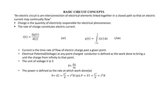
- 1. BASIC CIRCUIT CONCEPTS “An electric circuit is am interconnection of electrical elements linked together in a closed path so that an electric current may continually flow” Charge is the quantity of electricity responsible for electrical phenomenon. The rate of charge constitutes electric current. ⅈ 𝑡 = ⅆ𝑞 𝑡 ⅆ 𝑡 𝑞 𝑡 = −∞ 𝑡 ⅈ 𝑥 ⅆ𝑥 c/sec • Current is the time rate of flow of electric charge past a given point. • Electrical Potential(Voltage) at any point charged conductor is defined as the work done to bring a unit the charge from infinity to that point. • The unit of voltage V or E V= ⅆ𝜔 ⅆ𝑞 • The power is defined as the rate at which work done(w) P= 𝐸𝐼 = 𝐸2 𝑅 = 𝐼2𝑅 (or) 𝑃 = 𝑉𝐼 = 𝑣2 𝑅 = 𝐼2𝑅 (or)
- 2. Energy is the capacity to do work (kwh or unit) W= 𝐸𝐼𝑇 = 𝐸2𝑡 𝑅 = 𝐼2𝑅 Elements of electric circuits: Electric circuit consists of two types of elements 1.Active elements or Sources 2.Passive elements or Sinks. 1.Active elements: They are the elements of the circuits which posses energy of their own and can impact it to other elements on the circuits”[Independent sources] They are two types of Active elements 1.Voltage Source 2.Current Source “An ideal voltage source is one ,which delivers energy to a load at constant terminal voltage irrespective of the current drawn from the load.” “An ideal Current source is the one ,which delivers energy with a constant current to the load, irrespective of the terminal voltage at the load.”
- 3. Symbolically: a)Ideal DC Voltage sources b)Ideal DC Current Source c)Practical Current Source d)Practical Current Source e)Ideal &practical AC voltage sources
- 4. Dependent Sorces: Dependent Sorces are special kind of Sources in which the source voltage or Current depends upon a current or voltage elsewhere in the circuit. 2.Passive Elements: “These are the elements of an electric circuit which don not posses energy of their own.” They receive energy from the Sources. Exapmles:Resistance,inductance,capacitance Resistance: is the property of the conductor by virtue of which it opposes or limits the flow of current through it.unit is ohm(𝛺). 𝑅 = 𝜌𝑙 𝑎 𝜌=Resistivity: 𝑙 = 𝐿𝑒𝑛𝑔ℎ𝑡ℎ 𝑜𝑓 𝑡ℎ𝑒 𝑐𝑜𝑛𝑑𝑢𝑐𝑡𝑜𝑟: 𝑎 = 𝑎𝑟𝑒𝑎 𝑜𝑓 𝑡ℎ𝑒 𝑐𝑟𝑜𝑠𝑠 𝑠𝑒𝑐𝑡𝑖𝑜𝑛 a)Dependent voltage source b)Dependent current Source
- 5. A pure inductance does not consumes any power and the energy given to it is stored in the form of electromagnetic filed and is given by 𝐸 = 1 2 𝐿𝐼2 w𝑠ⅇC I=Current flowing through the inductor. A pure capacitance does not consume any amount of power,and the energy given to it is stored in the form of electrostatic filed and is given by 𝐸 = 1 2 𝑐𝑣2 v= voltage applied across a capacitor. Ohm’s law: In a temperature constant ,the current through any conductor is directly proportional to the potential difference between two ends of the conductor.” 𝐼 𝛼 𝑣 𝐼 ∝ 𝑣 𝑅 V = IR
- 6. Definitions: 1.Circuit element: Any individual ckt component with 2 terminals by which it can be connected to other electric components. 2.Branch:A group of ckt elements,usually in series & with 2 terminals 3.Potential Source(Independent):A hypothetical generator which maintains its value of potential independent of the output current ,an a.c. source will be indicated by a enclosing a wary line.
- 7. 4. Current Source (Independent):- A generator which maintains its output of the voltage across its terminals. It is indicated by a circle enclosing on arrow for reference elements current direction. 5. Network & Circuit:- An electric network is any possible interconnection of electric circuit elements (or) branches. • An electric circuit is a closed energized network. A network is not necessarily a circuit. Ex: T-network 6. Lumped Network:- A network in which physically separate resistors , capacitance & inductors can be represented. 7. Distributed Network:- One in which resistors, capacitors & inductors cannot be electrically separated & individually isolated as separate elements. Ex: Transmission line
- 8. 8. Passive Network:- A network containing circuit elements without only energy sources. 9. Active Network:- A network containing energy sources together with other circuit elements. 10. Linear elements:- A circuit elements is linear if the relation between current and voltage involves a constant co-efficient. Ex: v=Ri, v=L di/dt, v=1/c A linear network is one in which principle of superposition holds. A non-linear network is one which is not linear. 11. Mesh & Loop :- A set of branches forming a closed path, with the omission of any branches making the path open. Mesh must not have any other circuit inside it. Loop may have other loops (or) meshes inside it. idt
- 9. 12. Node (or) Junction :-A terminal of any branch of a network common to two (or) more branches is known as a node voltage of any node with respect to ground is the node voltage. Voltage between any pair of nodes is the node pair voltage. 13.Vector & Phasor :-Vector is generalized multidimensional quantity having both magnitude & direction. Phase is a 2 dimensional vector used in electrical technology which relates to voltage & current. 14.Bilateral & Unilateral elements:-A bilateral element, the same relation exists between voltage & current flowing in either direction. Example:- Voltage Source, Current Source. An unilateral is one, in which the same relation does not (hold) exist between the voltage & current either direction. Example:- Silicon diode, Vaccum diode.
- 10. Fig :- Lumped Network Resistance in series:-
- 11. • Let R1, R2 & R3 be 3 resistors connected in series and V1, V2 & V3 be their corresponding voltage drops respectively. • Let V be the total voltage applied and I be the current flowing through the circuit. V = V1 + V2 + V3 IR = IR1 + IR2 + IR3 Similarly with n resistor in series, the total resistance is R = R1 + R2 + …….. +Rn. Resistance in parallel:- R = R1 + R2 + R3 Total resistance I1 I2 I3
- 12. Let I1, I2 & I3 be the currents flowing through R1, R2 & R3 respectively I = I1 + I2 + I3 i.e, V/R = V/R1 + V/R2 + V/R3 Therefore, Note:- R = (R1R2)/(R1+R2) Kirchhoff’s Law:- 1. Kirchhoff’s Voltage Law: In algebraic sum of all branch voltages around any closed loop of a network is zero at all instances of time. 1/R = 1/R1 + 1/R2 + 1/R3 1/R = 1/R1 + 1/R2 + ……. + 1/Rn
- 13. (a) Consider an electrical circuit with six nodes A, B, C, D, E, F as shown in the figure. Applying KVL to the above circuit, V - V1 - V2 - V3 - V4 - V5 = 0 i.e. Σ V = 0
- 14. 1. Kirchhoff’s Current Law: The algebraic sum of branch currents at a node is zero at all instances of time. I1 + I2 – I3 – I4 = 0 Σ I = 0 Note : Currents entering the node are taken as +ve and leaving the node are taken as -ve.
- 15. V = V1 + V2 V = V1 + IR2 V = V1 + (V/R)R2 V = V1 + (V/R1 + R1)R2 V1 = VR1 / (R1+R2) Similarly, V2 = VR2 / (R1+R2)
- 16. I = I1 + I2 I = I1 + V/R2 I = I1 + IR/R2 I1 = I[1-R/R2] I1 = I[1-R/R2] I1 = I[1-(R1R2/R1+R2)/R2] I1 = I[R1+R2-R1/R1+R2] Similarly, I1 = IR2/R1+R2 I2 = IR1/R1+R2
- 17. Problems Sol: Rs = R1 + R2 + R3 Rs = 10 + 12 + 5 Rs = 27 Ω 1) | V | Applied Voltage
- 18. 2) A Sol: Rp = (R1 * R2)/R1 + R2 Rp = (10*10)/10+10 Rp= 5 Ω 10 Ω 10 Ω B
- 19. 3) • Find the current in each resistance and voltage across 10 Ω. Find also the power consumed in all the resistances. 20 Ω 40 Ω I1 I2 20 Ω It 200V
- 20. Sol: The net resistance is, Rt = 10 Ω + ((20*40)/20+40) = 23.33 Ω It = Vt/Rt = 200/23.33 = 8.57 A I1 = (I*40)/(20+40) = (8.57*40)/60 = 5.71 A Similarly I2 = (8.57*20)/(20+40) = 2.86A
- 21. V10Ω = I * 10 = 8.57 *10 = 85.7 volts P=(V*I) = I*I*R P10Ω = 8.57*8.57*10 = 734.449 W P20Ω = 5.71*5.71*20 = 652.082 W P40Ω = 2.86*2.86*40 = 327.184 W 3 resistors A,B,C are considered in parallel taking a total current of 12 A from the supply. If Ib = 2Ia , Ic = 3.5Ib a)Current drawn by each resistor b)Supply voltage c)Power consumed by each resistor 4)
- 22. a) Apply KCL at node A I = Ia +Ib +Ic I2 = Ia + (2*Ia) + 3.5*Ib I2 = Ia + (2*Ia) + 3.5(2*Ia) Ia = 1.2 A IA IB IC RA RB RC A B I V
- 23. Ib = 2Ia = 2*(1.2) = 2.4 A Ic = 3.5*Ib = 8.4 A b) P = V * I V = P / I = 3K/I2 = 250 V c) P = V * I Pa = V * Ia = 300 W Pb = V * Ib = 600 W Pc = V * Ic = 2100 W
- 24. I2 V I1 4Ω I 24Ω 10Ω 8Ω 12Ω 8Ω 50V 5) In the circuit given find the voltage drop across 4Ω resistor and the supply voltage.
- 25. Sol: Let I1, I2, I be the currents flowing in the branches as shown in figure. I1 = 50/10 = 5 A I2 = 50/8 = 6.25 A I = I1 + I2 = 11.25 A V4 Ω = 4 * I = 4 * 11.25 = 45 V Rt = ( 24 || 12 || 8) + (10 || 8) + 4
- 26. 24 Ω || 12 Ω = (24*12)/(24+12) = 8Ω 8 Ω || 8 Ω = (8*8)/(8+8) = 4 Ω 10 Ω || 8 Ω = (10*8)/(10+8) = 4.44 Ω 8 8 4 10 24 12
- 27. Rt = 4 + 4.44 + 4 = 12.44 Ω V = Rt * I = 12.44 * 11.25 = 140 V 6) I1 I2 I3 20Ω 20Ω R 25V 5Ω I = 2.5 Find the value of R
- 28. Sol : V5Ω = 2.5 * 5 = 12.5 Voltage across parallel combination = 25 – 12.5 = 12.5 V I1 = 12.5/20 = 0.625 A = I2 But I = I1 + I2 + I3 2.5 = 0.625 + 0.625 + I3 I3 = 1.25 A R = 12.5/ I3 = 12.5/1/25 = 10 Ω
- 29. 7. A resistance R is connected in series with a parallel circuit comprising 20 Ω and 48 Ω. The total power dissipated in the circuit is 1000 W and the applied voltage is 250 V . Calculate R 20 Ω 48 Ω R 250 V
- 30. sol: P = (V * V) / Rt = 1000 (250 * 250)/Rt = 1000 Rt = 62.5 Ω Rt = R + [(20*48)/(20+48)] = 62.5 R = 48.38 Ω Source Transformation: • Source transformation is a procedure which transforms one source into another while retaining the terminal characteristics of the original source. • An equivalent circuit whose terminal characteristics remain identical to those of the original circuit.
- 31. Rs i V R Y Y Vs Is X X V R i (a) (b)
- 32. • We want to transform the circuit in (a) to (b). • For all values of R both the circuits should have some characteristics between the terminal X and Y. • If R = 0, X Y short circuited. in fig(a) i = Vs/Rs in fig(b) the short circuit current is I3 i3 = V3/R3 ----- (1) • If R = ∞ XY open circuited in fig (a) V = Is * Rp in fig (b) the open circuit voltage is Vs Vs = Is * Rp -------- (2) Sub Eqn 1 in Eqn 2 Vs = (Vs/Rs) * Rp Rs = Rp
- 33. • Applying KVL to fig (a) Vs – (i*Rs) – V = 0 Vs = (i*Rs) + V Vs/Rs = I + (V/Rs) ---- (3) • Applying KCL to fig(b) Is = I + (V/Rp)--------- (4) thus fig(a) and fig(b) are equivalent if, is = (Vs/Rs) and Rs = Rp
- 34. Note: 1. A current source I in parallel with a resistor R can be replaced by a voltage source if V = I * R in series with a resistor R. 2. Reverse is also true. 3. V = I * R
- 35. PROBLEMS
- 36. 1) Sol 2Ω 20V 2Ω 10A I = (V/R) = 20/2 = 10 A =
- 37. 2) 2Ω 20V 2Ω 10A V = I * R = 10 * 2 = 20 V =
- 38. NOTE : a) V1 V2 = V = V1 + V2
- 39. i1 i2 i = i1 + i2 b)
- 40. V1 V2 V = V1 - V2 c)
- 41. i1 i2 i = i1 - i2 d)
- 42. e) V1 V2 R1 R2 R = R1 + R2 V = V1 + V2
- 43. f) i1 i2 R1 R2 i = i1 + i2 R = R1 || R2
- 44. R1 R2 V1 V2 R1 R2 i1 = V1/R1 i2 = V2/R2 i = i1 + i2 R = (R1 * R2) (R1 + R2) g)
- 45. 6V 2Ω 3V 1Ω 8V 2Ω 6V 1Ω Reduce the circuit to Single Voltage Source and resistor X Y
- 46. X Y 2Ω 3A 1Ω 3A 4A 2Ω 6A 1Ω
- 49. X Y 4/3Ω 32/3V
- 51. R2 R1 R3 V V V
- 52. R2 R1 R3 V V V
- 53. b) a b c R2 d R1 R3 I-Shift i
- 54. a b R1 R3 c R2 d i i i
- 57. R1 R2 E R4 R5 R3
- 58. I =
- 59. Reduce the circuit to a single circuit source and a single resistor in parallel to it. 4Ω 4Ω a 4Ω b 9V 9V 5A 4Ω
- 60. Dummy has no effect 4Ω 4Ω a 9V 9V 5A 4Ω 4Ω b
- 61. 4Ω 4Ω 5A 9V
- 62. 9/4 A 4Ω 4Ω 5 A
- 63. 7.25 A 2Ω
- 64. 5) Find the current i, by the reducing the circuit to the right to its simplest form. Sol:- Step 1:- Transform 30 resistor 3v source into current source and parallel resistance.
- 65. Step 2 :- Reducing parallel resistors 20 and 30 , we have 20x30/20+30 = 12 Step 3 :- Current source to voltage source
- 66. KVL, 5-5i-12i-1.2 = 0 therefore, i = 0.2235A Source shifting V2=3V Vab = 3.6v
- 67. Star-Delta Transformation (a) Delta Connection (b) Star (or) Y Connection Delta to Star Transformation ( to y) :-
- 68. Let RAB, RBC & RCA be the 3 resistors connected in delta as shown in fig(a) and RA, RB & RC be the 3 equivalent resistances connected in star (y) as shown in fig(b). “Principle of Conversion is that the equivalent resistance between the corresponding points in both the connections is some”. Therefore, RA + RB = RAB || (RCA + RBC) RA + RB = RAB(RCA + RBC) / RAB + RBC + RCA = RAB(RCA+RBC) / RAB ---------- (1) Similarly, RB + RC = RBC(RAB + RCA) / RAB + RBC + RCA = RBC(RCA+RAB) / RAB ---------- (2)
- 69. RC + RA = RCA(RAB+RBC) / RAB -------- (3) (1) – (2) RA – RC = RAB RCA – RBC RCA/ RAB ------- (4) (3) + (4) 2RA = 2RAB RCA/ RAB Therefore, RA = RAB RCA/ RAB ------- (5) Similarly, RB = RBC RAB / RAB -------(6) RC = RBC RCA / RAB -------(7) Star to Delta Transformation :- From equ (5),(6) & (7) we can write
- 70. RARB + RBRC +RCRA = RAB RBC RCA (RAB+RBC+RCA) / ( RAB)^2 = RBC * RAB RCA / RAB = RBC RA Similarly, RBC = RB + RC +RBRC / RA RAB = RA + RB +RARB / RC RCA = RC + RA +RCRA / RB Problems:- 1.)
- 71. RA = RAB RCA / RAB = 4 * 4 / (4 +4 + 4) = 1.33 Similarly, RB = RC 1.33 2.)
- 72. 3.) RA = 5 , RB = 10 , RC = 20 RA = RA + RB + RARB / RC
- 73. 4.) Find the equivalent resistance between A & B ? Sol:- Equivalent resistance is 3*6/3+6 = 2
- 74. 5.) Find the resistance between A & B ? 6.) Find the resistance between A & B ? Answer :- 10K
- 75. 7.) Determine the resistance between the terminates M & N if the network shown? 8.) Determine the resistance between the points A & B is the network shown?
- 76. 9.) Find the current supplied by the source to the network shown
- 77. 10.) Obtain the equivalent resistance RAB for the circuit & hence find i? 11.)
- 78. Mesh Analysis with independent voltage source:- consider the circuit, + - Applying kvl to each mesh, Mesh1: v-i1R1-R3(i1-i2) = 0 ------(1) Mesh2: v-i2R2-(i2-i1)R3 = 0 -------(2) Once Mesh currents are known branch currents can be found out. Eg: 1) Determine the loop currents & all branch currents
- 79. Applying kvl to Mesh, Mesh1: 10-0.2i1-2(i1-i3)-3(i1-i2) = 0 5.2i1-3i2-2i3 = 10 ------(1) Mesh2: -3(i2-i1)-4(i2-i3)-0.2i2-15 = 0 -3i1+7.2i2-4i3 = -15 -----(2) Mesh3: -5i3-4(i3-i2)-2(i3-i1) = 0 -2i1-4i2+11i3 = 0 ------(3)
- 80. Using cramers rule, i1 = 0.11A i2 = -2.53A i3 = -0.9A 2.) Find the power dissipated in the 80ohm resistor using Mesh Analysis