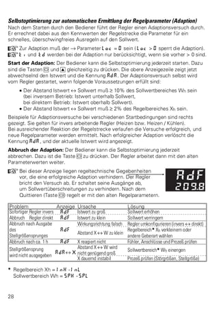
16-mal heruntergeladen
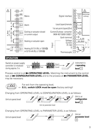
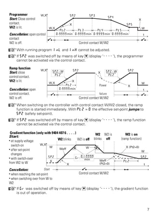
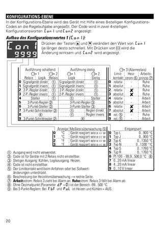
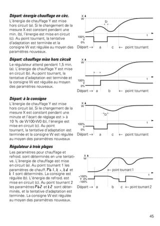
![ADJUSTER OPERATING LEVEL
Switching off relay 1, heating current monitoring and control contact L/R are as
described for controllers. Control contact W/W2 is ineffective. The other conditions
are as follows:
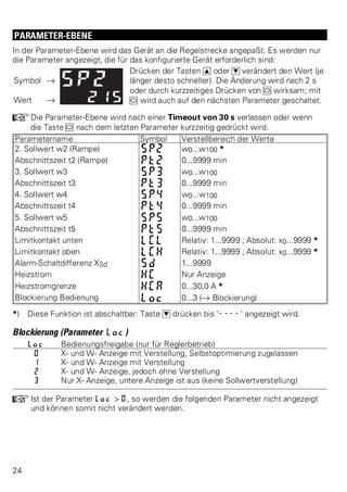
Process value display (only with 3-point stepping adjuster)
Displaying/adjusting the correcting value (all other adjusters)
p Correcting values for heating: H... p for cooling: C...
Pressing keys I D changes the correcting value display (the longer the faster). The
change is effective after 2 s or by pressing M shortly. With 3-point stepping
adjusters, the motor actuator is adjusted directly.
The correcting value for two-point or three-point adjuster is determined from formula
Y = rel. duty cycle [%] =
Ton . 100 %
Ton + Toff
The parameters for cycle time (Ton + Toff at Y = 50%) are set as t1 or t2.
+W2 is on: The adjuster is in remote mode (control contact L/R closed). Thereby,
adjusting the correcting value with the keys is not possible.
Display of the relay statuses
The limit contact is without effect, the LC LED is off. LEDs H and C indicate the relay
statuses for heating and cooling. With the outputs switched off ( H 0) and with
continuous adjusters, the LEDs remain off.
Switching off and on again the outputs
Switching off: Set correcting value to H 0 by means of key D. Switch. off causes:
w all relay outputs and the logic output (terminal 17/18) are switched off,
w the continuous output is set to 0 mA,
Switching on: Increase the output by pressing key I. With 3-point adjusters,
changing the heating or cooling output accordingly is done by means of keys I and D.
INTERFACE
Information on the interface is given in operating notes 9499 040 15601 for the
interface module and in interface description 9499 040 26218.
MAINTENANCE / BEHAVIOUR IN CASE OF TROUBLE
The controller needs no maintenance. The rules to be followed in case of trouble are:
w Check, if all connections are correct.
w Shut down the controller and replace it.
16](https://image.slidesharecdn.com/ks40v2-140925082749-phpapp01/85/Regulateur-KS40-v2-18-320.jpg)
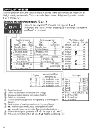
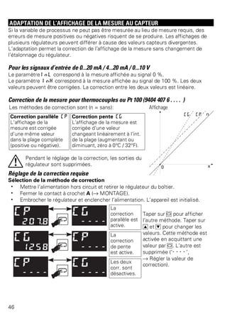
![BEDIEN-EBENE - STELLER
Das Abschalten des Relais 1, die Heizstromüberwachung und der
Steuerkontakt L/R sind wie bei Reglern beschrieben. Der Steuerkontakt W/W2 ist
wirkungslos. Die weiteren Bedienungen sind wie folgt:
Anzeigen des Istwertes (nur bei 3-Punkt-Schrittsteller)
Anzeigen/Verstellen des Stellwertes (alle anderen Steller)
p Stellwerte für Heizen: H... p Stellwerte für Kühlen: C...
Drücken der Tasten I D ändert die Stellwertanzeige (je länger desto schneller).
Die Änderung wird nach 2 s oder durch kurzzeitiges Drücken von M wirksam.
Bei 3-Punkt-Schrittstellern wird der Stellmotor unmittelbar verstellt.
Der Stellwert für Zweipunkt- und Dreipunkt-Steller ergibt sich aus der Formel
Y = relative Einschaltdauer [%] =
Tein . 100 %
Tein + Taus
Die Schaltperiodendauer (Tein + Taus bei Y = 50%) wird als t1 bzw. t2 parametriert.
+W2 ist ein: Der Steller ist im Remote-Betrieb (Steuerkontakt L/R geschlossen).
Dabei ist eine Verstellung des Stellwertes mit den Tasten nicht möglich.
Anzeigen der Relaiszustände
Der Limitkontakt ist wirkungslos, die LC-LED ist aus. Die LEDs H und C zeigen die
Relaiszustände für Heizen und Kühlen an. Sind die Ausgänge abgeschaltet ( H 0)
und bei stetigen Stellern bleiben die LEDs aus.
Ausgänge abschalten und wieder einschalten
Abschalten: Stellwert mittels Taste D auf H 0 stellen. Die Abschaltung bewirkt:
w alle Relaisausgänge und der Logikausgang (Anschluß17/18) werden abgeschaltet,
w der stetige Ausgang wird auf 0 mA gesetzt,
Einschalten: Mit der Taste I wird der Stellwert erhöht. Bei 3-Punkt-Stellern wird mit
den Tasten I und D der Heizen- oder der Kühlen-Stellwert entsprechend verändert.
SCHNITTSTELLE
Informationen zur Schnittstelle enthalten der Bedienhinweis 9499 040 15601 des
Schnittstellenmoduls und die Schnittstellenbeschreibung 9499 040 26218.
WARTUNG / VERHALTEN BEI STÖRUNG
Der Regler ist wartungsfrei. Im Falle einer Störung sind folgende Punkte zu beachten:
w Überprüfung aller Anschlüsse auf korrekten Anschluß.
w Regler außer Betrieb nehmen und austauschen.
32](https://image.slidesharecdn.com/ks40v2-140925082749-phpapp01/85/Regulateur-KS40-v2-34-320.jpg)
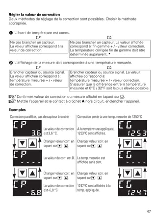
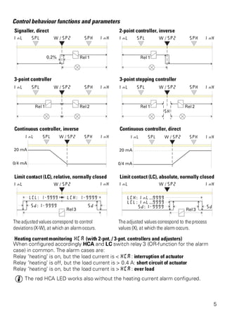
![«UTILISATION EMETTEUR»
La mise hors circuit du relais 1, la surveillance courant chauffage et le contact de
commande L/R sont comme décrits pour les régulateurs. Le contact de commande
W/W2 est ineffectif. Les autres conditions sont:
Affichage mesure (seulem. émetteur 3 pl.pas-à-pas)
Affichage/Réglage valeur correction (tous les autres émett.)
p Valeurs correction chauff.: H... p correction refroid.: C...
Taper sur I D pour changer l’affichage de la valeur de corr. (d’autant plus rapidemt
que plus longtemps). La modif. est effective après 2 s ou en tapant brièvement sur
M. Emetteur 3 plages pas-à-pas: l’organe de réglage est réglé directement.
Déterminer la valeur de corr. pour émett. 2 ou 3 plages à partir de la formule
Y = cycle [%] =
Ten . 100 %
Ten + Thors
Les paramètres (temps du cycle, Ten+Thors à Y = 50%) sont réglés comme t1 ou t2.
+W2 allumé: L’émetteur est en «à distance» (contact de commande L/R fermé).
Le réglage de la valeur de correction par les touches n’est pas possible.
Affichage des états des relais
Le contact limite est sans effet, la LED LC est éteinte. Les LED H et C indiquent les
états des relais chauffage et refroid. Si les sorties sont supprimées ( H 0) et sur les
émetteurs continus, les LED restent éteintes.
Suppression et remise en circuit des sorties
Suppression: Mettre la sortie à H 0 en tapant sur D. La suppression provoque:
w mise hors circuit toutes sorties relais et sortie logique (borne 17/18),
w mise à 0 mA sortie continue,
Mise en circuit: Augmenter valeur correction en tapant sur I. Emetteurs à 3 plages:
changer valeur correction chauffage ou refroidissement en tapant sur I et D.
INTERFACE
Pour des renseignements sur l’interface, voir les notices d’utilisation 9499 040 15601
(module d’interface) et la description de l’interface 9499 040 26218.
ENTRETIEN / COMPORTEMENT EN CAS DE PANNE
Le régulateur n’exige pas d’entretien. Panne: tenir compte des renseignemts suivants:
w Vérifier si toutes les connexions sont correctes.
w Mettre le régulateur hors service et le remplacer.
48](https://image.slidesharecdn.com/ks40v2-140925082749-phpapp01/85/Regulateur-KS40-v2-50-320.jpg)

Das Dokument enthält Bedienungsanleitungen für einen Industrie-Controller, einschließlich Sicherheitsanweisungen, Montage-, Anschluss- und Konfigurationsdetails. Es beschreibt verschiedene Betriebs- und Parameterlevel sowie deren Anpassung und Funktionsweisen, einschließlich der Optimierungshilfen und Selbstoptimierung. Zudem werden elektrische Anschlüsse, technische Daten und spezifische Konfigurationscodes erläutert.


