
Empfohlen
Weitere ähnliche Inhalte
Ähnlich wie PCD insert-CBN insert
Ähnlich wie PCD insert-CBN insert (14)
PCD insert-CBN insert
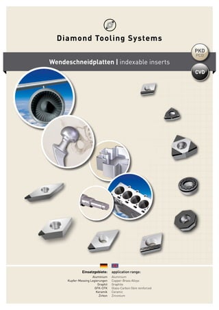
- 1. Einsatzgebiete: Aluminium Kupfer-Messing Legierungen Graphit GFK-CFK Keramik Zirkon application range: Aluminium Copper-Brass Alloys Graphite Glass-Carbon fibre reinforced Ceramic Zirconium Wendeschneidplatten | indexable inserts PCD PKD CVD
- 2. DE | ENGDiamond Tooling Systems GmbH Mit Sitz in Kaiserslautern-Deutschland haben wir uns auf die Entwicklung, Herstellung und den Vertrieb von Präzisionswerk- zeugen aus ultraharten Schneidstoffen wie CVD-D (CVD-Dickfilm Diamant), PKD (Polykristalliner Diamant) und CBN (Kubisches Bornitrid) spezialisiert und national so wie international erfolg- reich am Markt etabliert. Um diese ultraharten Schneidstoffe wie PKD, CBN und den CVD-Dickfilm Diamant auf Präzisionwerkzeugen wirtschaftlich bearbeiten zu können haben wir schon früh erkannt, dass wir uns von der alten Produktionstechnologie „Schleifen“ hin zu neuen Technologien wie der „Lasertechnologie“ weiterentwickeln müssen. Ultraharte Hochleistungsschneidstoffe haben eine Schlüssel- funktion in der spanenden Fertigung. Präzisionswerkzeuge aus ultraharten Schneidstoffen sind sehr erklärungsbedürftige Produkte. Der wirtschaftliche Einsatz der Schneidstoffe ist nur sichergestellt, wenn der Zerspanungspro- zess und der Schneidstoff aufeinander abgestimmt sind. Genau hier setzt Diamond Tooling Systems GmbH an, „Unse- re Kernkompetenz sind Präzisionswerkzeuge aus ultrahar- ten Schneidstoffen“. Diese Hightech-Werkzeuge müssen zum Zerspanungsprozess mit Anwendungstechnikern genau abge- stimmt werden, nur so ist es möglich, das optimale Potenzial auszuschöpfen. Mit mehr als 25 Jahren Optimierungserfahrung in der verar- beitenden Industrie sehen wir hier unsere Stärke! Während der laufenden Produktion stehen wir Ihnen mit unseren erfahrenen Anwendungstechnikern beratend zur Seite. Diese enge Zusam- menarbeit und das gegenseitige Vertrauen ist die Basis unseres Erfolges. Located in Kaiserslautern, Germany we are specialized in the development, production and sales of precision tools made from ultra-hard cutting materials such as CVD-D (CVD, thick film di- amond), PCD (polycrystalline diamond) and CBN (cubic boron nitride). We have successfully established these in national and international markets. In order to economically process these ultra-hard cutting materi- als such as PCD, CBN and CVD thick film diamond onto precision tools we noticed at an early stage that we should move on from the older manufacturing technologies such as grinding and advance to newer technologies such as laser technology. Ultra-hard high-performance cutting materials now have a key function and place in the metal cutting industry and production. Precision tools from ultra-hard cutting materials are products which require a more depth of explanation. The economical usage of these materials provides a guarantee when the cutting process and cutting materials are fully aligned. This is where “Diamond Tooling Systems GmbH” comes into the picture. We provide these precision tools made from such ultra-hard cutting materials. These high-tech tools require together with an experienced appli- cation engineer a need to be aligned with the cutting process in order to exploit their optimal potential. Our strengths lie in having more than 25 years of optimization experience within the produ cing industry. During the initial stages of running production, we will be by your side offering a professional consultation service along with our experienced application engineers. This side by side cooperation based on mutual trust is the keystone of our success. Frankfurt am Main Stuttgart Karlsruhe Saarbrücken Kaiserslautern Mannheim Koblenz Mainz Wiesbaden Kaiserslautern 22
- 3. DE | ENGInhalt | content Schneidstoffgruppen groups of cuttingmaterial......................... 5 ISO Nummernschlüssel ISO codes.................................................. 6 Wiper Geometrien wiper geometries...................................... 7 Formeln formulas.................................................... 7 Schnittdaten Empfehlungen recommended cutting parameters.......... 8 CCGT | Z1................................................. 10 CCGT | R-GS | entire edge right.............. 11 CCGT | L-GS | entire edge left................. 12 CCGW | Z1............................................... 13 CCGW | R-GS | entire edge right............. 14 CCGW | L-GS | entire edge left............... 15 CDGW | Z2............................................... 16 CNGA | Z1................................................ 17 CPGT | Z1................................................ 18 CPGW | Z1............................................... 19 DCGT | Z1................................................ 20 DCGW | Z2............................................... 21 DCGW | Z1............................................... 22 DXGW | Z1............................................... 23 DNGA | Z1................................................ 24 EPGW | Z2............................................... 25 ODGW | FullFace Z8................................ 26 RBGN | FullFace..................................... 27 RCGW | FullFace..................................... 28 RDHX | FullFace..................................... 29 SCGT | Z1................................................. 30 SCGT | GS | entire edge........................... 31 SCGW | Z1............................................... 32 SCGW | GS | entire edge......................... 33 TCGT | Z1................................................. 34 TCGT | GS | entire edge........................... 35 TCGW | Z1................................................ 36 TCGW | GS | entire edge.......................... 37 TCGW | FullFace..................................... 38 TPGN | Z1................................................ 39 TPGN | GS | entire edge.......................... 40 TPGW | Z1............................................... 41 VBGT | Z1................................................ 42 VBGW | Z1............................................... 43 VCGT | Z1................................................. 44 VCGW | Z2................................................ 45 VCGW | Z1................................................ 46 VXGW | Z1............................................... 47 WCGW | Z3.............................................. 48 WCGW | FullFace Z3............................... 49 33
- 4. DE | ENGNotizen | notes 44
- 5. DE | ENGSchneidstoffgruppen | groups of cuttingmaterial 0 1.000 2.000 3.000 4.000 5.000 6.000 7.000 8.000 9.000 10.000 CVD-ThickfilmDiamond Naturdiamant natural diamond PKD PCD CBN CBN MKD MCD Keramik ceramic Hartmetall carbide Stahl steel Härte | hardness (kg/mm²) min.Binder CBN CVD PCD PKD CVD Dickfilm Diamant – der härteste Schneidstoff der Welt! Der ultraharte Schneidstoff „CVD-Dickfilm Diamant“ besitzt die höchste Härte und den höchsten Verschleiß- widerstand aller untersuchten Schneidstoffe. Der „PKD Schneidstoff“ hat im Gegensatz zum „CVD-Dickfilm Diamant“ deutliche Nachteile aufgrund seiner weichen metallischen Bindephase. In zahlrei- chen Versuchen konnte nachgewiesen werden, dass vor allem die weiche Bindephase des PKD durch die abrasi- ven Partikel geschädigt wird. Die Folge ist ein Ausbre- chen der Diamantkristalle aufgrund einer verminderten Verankerung in der Schneidstoffmatrix. Bei richtigem Einsatz von CVD-Dickfilm Diamant kön- nen die Standzeiten gegenüber PKD um das 3-10fache erhöht werden! CVD Thickfilm Diamond the hardest cutting material of the world! The mostly used “PCD cutting material” has in comparison to the “CVD-thickfilm diamond” clear drawbacks due to its soft metallic binder. In several tests it has been proven that especially the soft binder of the PCD is damaged through abrasive particles. The consequence is a break out of the diamond crystals due to a reduced anchorage in the cutting material matrix. The consequence of this is that by the machining of alumi- num – and magnesium alloys and also non ferrous mate- rials preferably diamond is used as cutting material. The clean diamond segments, which in most cases are brazed onto a carbide insert. The tool life can be increased with CVD thickfilm diamond approx 3 to 10 times vs. PCD. 55
- 6. DE | ENGISO Nummernschlüssel | ISO codes T N G A 16 04 08Plattentyp | insert type N W F R A T G M X Spezialausführung Special Type T N G A 16 04 08Toleranz (mm) | tolerance (mm) d m m d m d m d m d s T N G A 16 04 08Freiwinkel | clearance 3° 5° 7° 15° 20° 25° 30° 0° 11° A B C D E F G N P 120° 135° 108° 80° 55° 75° 86°90°85° 82° 55° 80°90° 60° Grundform | shape T N G A 16 04 08 C A W P V M T L S K R H O E D B 35° T N G A 16 04 08Plattengröße (mm) | insert size (mm) l W l P l T l L l S d R l H l O l C VM ED l A KB T N G A 16 04 08Dicke (mm) | insert size (mm) Bei Ziffern unter 10 wird eine Null vorgesetzt. Dezimalstellen bleiben unberücksichtigt. (Beispiel: 4,76 = 04) By numbers below 10 a 0 is added in at the front. Decimals remain unconsidered (example: 4,76 = 04) s s=1,5901 s=1,98T1 s=2,3802 s=3,1803 s=3,97T3 s=4,7604 s=5,5605 s=6,3506 T N G A 16 04 08Schneidenecke (mm) | corner configuration (mm) r=0,202 r=0,404 r=0,808 r=1212 r=1616 scharfe Ecke sharp corner00 runde Platte (inch) round insert (inch)00 runde Platte (metrisch) round insert (metric)M0 r m s d m s d A ± 0,005 ± 0,025 ± 0,025 ± 0,005 ± 0,025 ± 0,05 → ± 0,15 ± 0,005 ± 0,025 ± 0,013 ± 0,013 ± 0,025 ± 0,05 → ± 0,15 ± 0,013 ± 0,025 ± 0,025 ± 0,025 ± 0,025 ± 0,05 → ± 0,15 ± 0,013 ± 0,025 ± 0,013 ± 0,08 → ± 0,20 ± 0,130 ± 0,05 → ± 0,15 ± 0,025 ± 0,025 ± 0,025 ± 0,08 → ± 0,20 ± 0,25 ± 0,05 → ± 0,15 ± 0,025 ± 0,130 ± 0,025 ± 0,13 → ± 0,38 ± 0,130 ± 0,08 → ± 0,15 *(M, N, U) Die genaue Toleranz ist von der Größe der Platte abhängig | Die genaue Toleranz ist von der Größe der Platte abhängig 66
- 7. DE | ENGWiper Geometrien | wiper geometries Vorteile beim Einsatz von Wiper Geometrien Bei gleichem Vorschub kann eine 2 - 4fach bessere Oberflächen- güte erzielt werden oder bei 2 - 4fach höherem Vorschub kann die gleiche Oberflächengüte erzielt werden. Um die Wiper-Schneide in den Schnitt zu bekommen bitte folgende Anstellwinkel an der Maschine beachten: C und W Type = 95° D Type = 93° T Type = 91 Advantages when using wiper geometries By using the same feed rate a 2 - 4 times better surface quality can be obtained or with a 2 - 4 times higher feed rate the same surface quality can be reached. To get the wiper geometry into cutting condition please use following lead angles at the machine: C and W Type = 95° D Type = 93° T Type = 91 Formeln | formulas 77 r Rt f r f Rt Wiper Geometrie wiper geometrie metrisch | metric Zoll | inch Formel | formula Einheiten | units Formel | formula Einheiten | units Vorschubgeschwindigkeit feed rate Vf = fn x n mm / min Vf = fn x n Zoll / min inch / min Spindeldrehzahl spindle speed n = Vc x 1000 π x DCap U / min rev / min n = Vc x 12 π x DCap U / min rev / min Vorschub pro Umdrehung feed per revolution fn = Vf n mm / U mm / rev fn = Vf n Zoll / U inch / rev Bearbeitungszeit cutting time Tc = lm fn x n min Tc = lm fn x n min Zeitspanvolumen stock removal rate Q = Vc x ap x fn cm3 / min Q = Vc x ap x fn x 12 Zoll3 / min inch3 / min
- 8. Schnittdaten Empfehlungen | recommended cutting parameters PCD PKD Neutral / Positiv P N WSP Spanwinkel 0° + pos. Inserts rake angle 0° + pos. mit Schlicht-Spanleitstufe with finishing chip breaker mit Schrupp-Spanleitstufe with roughing chip breaker Vc ap f Vc ap f Vc ap f Werkstoff | material r min max min max min max min max min max min max min max min max min max Aluminium- Knetlegierung Si < 1% Aluminium alloys Si < 1% 0,1 80 6000 0,01 2,80 0,01 0,05 80 6000 80 6000 0,2 80 6000 0,01 2,80 0,01 0,10 80 6000 0,06 1,50 0,02 0,10 80 6000 0,12 2,80 0,08 0,10 0,4 80 6000 0,01 2,80 0,01 0,20 80 6000 0,06 2,00 0,04 0,20 80 6000 0,12 2,80 0,12 0,20 0,8 80 6000 0,01 2,80 0,01 0,40 80 6000 0,06 2,40 0,08 0,40 80 6000 0,12 2,80 0,25 0,40 1,2 80 6000 0,01 2,80 0,01 0,60 80 6000 0,06 2,85 0,12 0,60 80 6000 0,12 2,80 0,30 0,60 Aluminium- Knetlegierung Si < 12% Aluminium alloys Si < 12% 0,1 80 4000 0,01 2,80 0,01 0,05 80 2000 80 3000 0,2 80 4000 0,01 2,80 0,01 0,10 80 2000 0,06 1,50 0,02 0,10 80 3000 0,12 2,80 0,08 0,10 0,4 80 4000 0,01 2,80 0,01 0,20 80 2000 0,06 2,00 0,04 0,20 80 3000 0,12 2,80 0,12 0,20 0,8 80 4000 0,01 2,80 0,01 0,40 80 2000 0,06 2,40 0,08 0,40 80 3000 0,12 2,80 0,25 0,40 1,2 80 4000 0,01 2,80 0,01 0,60 80 2000 0,06 2,85 0,12 0,60 80 3000 0,12 2,80 0,30 0,60 Kupfer-Messing Legierungen Copper-Brass Alloys 0,1 80 4000 0,01 2,80 0,01 0,05 80 3000 80 5000 0,2 80 4000 0,01 2,80 0,01 0,10 80 3000 0,06 1,50 0,02 0,10 80 5000 0,12 2,80 0,08 0,10 0,4 80 4000 0,01 2,80 0,01 0,20 80 3000 0,06 2,00 0,04 0,20 80 5000 0,12 2,80 0,12 0,20 0,8 80 4000 0,01 2,80 0,01 0,40 80 3000 0,06 2,40 0,08 0,40 80 5000 0,12 2,80 0,25 0,40 1,2 80 4000 0,01 2,80 0,01 0,60 80 3000 0,06 2,85 0,12 0,60 80 5000 0,12 2,80 0,30 0,60 Keramik / Zirkon Ceramic / Zirconium 0,1 80 5000 0,01 2,80 0,01 0,05 80 3000 80 5000 0,2 80 5000 0,01 2,80 0,01 0,10 80 3000 0,06 1,50 0,02 0,10 80 5000 0,12 2,80 0,08 0,10 0,4 80 5000 0,01 2,80 0,01 0,20 80 3000 0,06 2,00 0,04 0,20 80 5000 0,12 2,80 0,12 0,20 0,8 80 5000 0,01 2,80 0,01 0,40 80 3000 0,06 2,40 0,08 0,40 80 5000 0,12 2,80 0,25 0,40 1,2 80 5000 0,01 2,80 0,01 0,60 80 3000 0,06 2,85 0,12 0,60 80 5000 0,12 2,80 0,30 0,60 GFK-CFK / Graphit Glass-Carbon- fibre reinforced / Graphite 0,1 80 6000 0,01 2,80 0,01 0,05 80 4000 80 6000 0,2 80 6000 0,01 2,80 0,01 0,10 80 4000 0,06 1,50 0,02 0,10 80 6000 0,12 2,80 0,08 0,10 0,4 80 6000 0,01 2,80 0,01 0,20 80 4000 0,06 2,00 0,04 0,20 80 6000 0,12 2,80 0,12 0,20 0,8 80 6000 0,01 2,80 0,01 0,40 80 4000 0,06 2,40 0,08 0,40 80 6000 0,12 2,80 0,25 0,40 1,2 80 6000 0,01 2,80 0,01 0,60 80 4000 0,06 2,85 0,12 0,60 80 6000 0,12 2,80 0,30 0,60 88
- 9. CVD Neutral / Positiv P N WSP Spanwinkel 0° + pos. Inserts rake angle 0° + pos. mit Schlicht-Spanleitstufe with finishing chip breaker mit Schrupp-Spanleitstufe with roughing chip breaker Vc ap f Vc ap f Vc ap f Werkstoff | material r min max min max min max min max min max min max min max min max min max Aluminium- Knetlegierung Si < 1% Aluminium alloys Si < 1% 0,1 20 6000 0,01 2,80 0,01 0,05 20 6000 20 6000 0,2 20 6000 0,01 2,80 0,01 0,10 20 6000 0,06 1,50 0,02 0,10 20 6000 0,12 2,80 0,08 0,10 0,4 20 6000 0,01 2,80 0,01 0,20 20 6000 0,06 2,00 0,04 0,20 20 6000 0,12 2,80 0,12 0,20 0,8 20 6000 0,01 2,80 0,01 0,40 20 6000 0,06 2,40 0,08 0,40 20 6000 0,12 2,80 0,25 0,40 1,2 20 6000 0,01 2,80 0,01 0,60 20 6000 0,06 2,85 0,12 0,60 20 6000 0,12 2,80 0,30 0,60 Aluminium- Knetlegierung Si < 12% Aluminium alloys Si < 12% 0,1 20 4000 0,01 2,80 0,01 0,05 20 2000 20 3000 0,2 20 4000 0,01 2,80 0,01 0,10 20 2000 0,06 1,50 0,02 0,10 20 3000 0,12 2,80 0,08 0,10 0,4 20 4000 0,01 2,80 0,01 0,20 20 2000 0,06 2,00 0,04 0,20 20 3000 0,12 2,80 0,12 0,20 0,8 20 4000 0,01 2,80 0,01 0,40 20 2000 0,06 2,40 0,08 0,40 20 3000 0,12 2,80 0,25 0,40 1,2 20 4000 0,01 2,80 0,01 0,60 20 2000 0,06 2,85 0,12 0,60 20 3000 0,12 2,80 0,30 0,60 Kupfer-Messing Legierungen Copper-Brass Alloys 0,1 20 4000 0,01 2,80 0,01 0,05 20 3000 20 5000 0,2 20 4000 0,01 2,80 0,01 0,10 20 3000 0,06 1,50 0,02 0,10 20 5000 0,12 2,80 0,08 0,10 0,4 20 4000 0,01 2,80 0,01 0,20 20 3000 0,06 2,00 0,04 0,20 20 5000 0,12 2,80 0,12 0,20 0,8 20 4000 0,01 2,80 0,01 0,40 20 3000 0,06 2,40 0,08 0,40 20 5000 0,12 2,80 0,25 0,40 1,2 20 4000 0,01 2,80 0,01 0,60 20 3000 0,06 2,85 0,12 0,60 20 5000 0,12 2,80 0,30 0,60 Keramik / Zirkon Ceramic / Zirconium 0,1 20 5000 0,01 2,80 0,01 0,05 20 3000 20 5000 0,2 20 5000 0,01 2,80 0,01 0,10 20 3000 0,06 1,50 0,02 0,10 20 5000 0,12 2,80 0,08 0,10 0,4 20 5000 0,01 2,80 0,01 0,20 20 3000 0,06 2,00 0,04 0,20 20 5000 0,12 2,80 0,12 0,20 0,8 20 5000 0,01 2,80 0,01 0,40 20 3000 0,06 2,40 0,08 0,40 20 5000 0,12 2,80 0,25 0,40 1,2 20 5000 0,01 2,80 0,01 0,60 20 3000 0,06 2,85 0,12 0,60 20 5000 0,12 2,80 0,30 0,60 GFK-CFK / Graphit Glass-Carbon- fibre reinforced / Graphite 0,1 20 6000 0,01 2,80 0,01 0,05 20 4000 20 6000 0,2 20 6000 0,01 2,80 0,01 0,10 20 4000 0,06 1,50 0,02 0,10 20 6000 0,12 2,80 0,08 0,10 0,4 20 6000 0,01 2,80 0,01 0,20 20 4000 0,06 2,00 0,04 0,20 20 6000 0,12 2,80 0,12 0,20 0,8 20 6000 0,01 2,80 0,01 0,40 20 4000 0,06 2,40 0,08 0,40 20 6000 0,12 2,80 0,25 0,40 1,2 20 6000 0,01 2,80 0,01 0,60 20 4000 0,06 2,85 0,12 0,60 20 6000 0,12 2,80 0,30 0,60 99
- 10. CCGT | Z1 Positiv P N Positiv Positive Spanleitstufe Chip breaker Spanleitstufe Chip breaker ISO-Code DTS Code DTS Code DTS Code DTS Code DTS Code DTS Code Klemmhalter Toolholder Standard CCGT 06 02 02 DP1010-0001 DP2010-0001 SCLC...06 A/E...SCLC.06 CCGT 06 02 04 DP1010-0002 DP2010-0002 CCGT 06 02 08 DP1010-0003 DP2010-0003 CCGT 09 T3 02 DP1010-0004 DP2010-0004 SCLC...09 A/E...SCLC.09 CCGT 09 T3 04 DP1010-0005 DP2010-0005 CCGT 09 T3 08 DP1010-0006 DP2010-0006 CCGT 09 T3 12 DP1010-0007 DP2010-0007 CCGT 12 04 02 DP1010-0008 DP2010-0008 SCLC...12 A...SCLC.12 CCGT 12 04 04 DP1010-0009 DP2010-0009 CCGT 12 04 08 DP1010-0010 DP2010-0010 Wiper CCGT 06 02 02 DP1010-0011 DP2010-0011 SCLC...06 A/E...SCLC.06 CCGT 06 02 04 DP1010-0012 DP2010-0012 CCGT 06 02 08 DP1010-0013 DP2010-0013 CCGT 09 T3 02 DP1010-0014 DP2010-0014 SCLC...09 A/E...SCLC.09 CCGT 09 T3 04 DP1010-0015 DP2010-0015 CCGT 09 T3 08 DP1010-0016 DP2010-0016 CCGT 12 04 02 DP1010-0018 DP2010-0018 SCLC...12 A...SCLC.12 CCGT 12 04 04 DP1010-0019 DP2010-0019 CCGT 12 04 08 DP1010-0020 DP2010-0020 10 PCD PKD PCD PKD PCD PKDCVD CVD CVD 80˚ r 7˚ 3
- 11. CCGT | Z1 R-GS Positiv P N Positiv Positive Spanleitstufe Chip breaker Spanleitstufe Chip breaker ISO-Code DTS Code DTS Code DTS Code DTS Code DTS Code DTS Code Klemmhalter Toolholder Standard CCGT 06 02 02 R-GS DP1020-0055 DP2020-0055 SCLCR...06 A...SCLCR.06 CCGT 06 02 04 R-GS DP1020-0001 DP2020-0001 CCGT 06 02 08 R-GS DP1020-0002 DP2020-0002 CCGT 09 T3 04 R-GS DP1020-0056 DP2020-0056 SCLCR...09 A...SCLCR.09 CCGT 09 T3 08 R-GS DP1020-0003 DP2020-0003 CCGT 09 T3 12 R-GS DP1020-0004 DP2020-0004 CCGT 12 04 04 R-GS DP1020-0057 DP2020-0057 SCLCR...09 A...SCLCR.09CCGT 12 04 08 R-GS DP1020-0005 DP2020-0005 11 Aluminium-Knetlegierung Aluminium alloys Kupfer-Messing Legierungen Copper-Brass Alloys Unser komplettes Halter-Programm finden Sie in unserem Klemmhalter- und Bohrstangen-Katalog. For complete tool holder programm please check our tool holder- and boring bar catalogue. Keramik / Zirkon Ceramic / Zirconium GFK-CFK / Graphit Glass-Carbonfibre reinforced / Graphite PCD PKD PCD PKD PCD PKDCVD CVD CVD 80° r 7° ISO
- 12. CCGT | Z1 L-GS Positiv P N Positiv Positive Spanleitstufe Chip breaker Spanleitstufe Chip breaker ISO-Code DTS Code DTS Code DTS Code DTS Code DTS Code DTS Code Klemmhalter Toolholder Standard CCGT 06 02 02 L-GS DP1020-0058 DP2020-0058 SCLCL...06 A...SCLCL.06 CCGT 06 02 04 L-GS DP1020-0045 DP2020-0045 CCGT 06 02 08 L-GS DP1020-0046 DP2020-0046 CCGT 09 T3 04 L-GS DP1020-0059 DP2020-0059 SCLCL...06 A...SCLCL.06 CCGT 09 T3 08 L-GS DP1020-0047 DP2020-0047 CCGT 09 T3 12 L-GS DP1020-0048 DP2020-0048 CCGT 12 04 04 L-GS DP1020-0060 DP2020-0060 SCLCL...06 A...SCLCL.06CCGT 12 04 08 L-GS DP1020-0049 DP2020-0049 12 PCD PKD PCD PKD PCD PKDCVD CVD CVD 80° r 7° ISO
- 13. CCGW | Z1 Neutral P N Neutral Neutral Spanleitstufe Chip breaker Spanleitstufe Chip breaker ISO-Code DTS Code DTS Code DTS Code DTS Code DTS Code DTS Code Klemmhalter Toolholder Standard CCGW 06 02 01 DP2010-0591 SCLC...06 A...SCLC.06 CCGW 06 02 02 DP1010-0021 DP2010-0021 DP1011-0001 DP2011-0001 DP1012-0001 DP2012-0001 CCGW 06 02 04 DP1010-0022 DP2010-0022 DP1011-0002 DP2011-0002 DP1012-0002 DP2012-0002 CCGW 06 02 08 DP1010-0023 DP2010-0023 DP1011-0003 DP2011-0003 DP1012-0003 DP2012-0003 CCGW 09 T3 02 DP1010-0024 DP2010-0024 DP1011-0004 DP2011-0004 DP1012-0004 DP2012-0004 SCLC...09 A...SCLC.09 CCGW 09 T3 04 DP1010-0025 DP2010-0025 DP1011-0005 DP2011-0005 DP1012-0005 DP2012-0005 CCGW 09 T3 08 DP1010-0026 DP2010-0026 DP1011-0006 DP2011-0006 DP1012-0006 DP2012-0006 CCGW 09 T3 12 DP1010-0027 DP2010-0027 DP1011-0007 DP2011-0007 DP1012-0007 DP2012-0007 CCGW 12 04 02 DP1010-0700 DP2010-0129 DP1011-0458 DP2011-0458 DP1012-0458 DP2012-0458 SCLC...12 A...SCLC.12 CCGW 12 04 04 DP1010-0028 DP2010-0028 DP1011-0008 DP2011-0008 DP1012-0008 DP2012-0008 CCGW 12 04 08 DP1010-0029 DP2010-0029 DP1011-0009 DP2011-0009 DP1012-0009 DP2012-0009 CCGW 12 04 12 DP1010-0030 DP2010-0030 DP1011-0010 DP2011-0010 DP1012-0010 DP2012-0010 Wiper CCGW 06 02 02 R/L-W DP1010-0031 DP2010-0031 DP1011-0011 DP2011-0011 DP1012-0011 DP2012-0011 SCLC...06 A...SCLC.06CCGW 06 02 04 R/L-W DP1010-0032 DP2010-0032 DP1011-0012 DP2011-0012 DP1012-0012 DP2012-0012 CCGW 09 T3 02 R/L-W DP1010-0034 DP2010-0034 DP1011-0014 DP2011-0014 DP1012-0014 DP2012-0014 SCLC...09 A...SCLC.09 CCGW 09 T3 04 R/L-W DP1010-0035 DP2010-0035 DP1011-0015 DP2011-0015 DP1012-0015 DP2012-0015 CCGW 09 T3 08 R/L-W DP1010-0036 DP2010-0036 DP1011-0016 DP2011-0016 DP1012-0016 DP2012-0016 CCGW 12 04 02 R/L-W DP1010-0038 DP2010-0038 DP1011-0018 DP2011-0018 DP1012-0018 DP2012-0018 SCLC...12 A...SCLC.12 CCGW 12 04 04 R/L-W DP1010-0039 DP2010-0039 DP1011-0019 DP2011-0019 DP1012-0019 DP2012-0019 CCGW 12 04 08 R/L-W DP1010-0040 DP2010-0040 DP1011-0020 DP2011-0020 DP1012-0020 DP2012-0020 13 Aluminium-Knetlegierung Aluminium alloys Kupfer-Messing Legierungen Copper-Brass Alloys Unser komplettes Halter-Programm finden Sie in unserem Klemmhalter- und Bohrstangen-Katalog. For complete tool holder programm please check our tool holder- and boring bar catalogue. Keramik / Zirkon Ceramic / Zirconium GFK-CFK / Graphit Glass-Carbonfibre reinforced / Graphite PCD PKD PCD PKD PCD PKDCVD CVD CVD 80° r 7° 3
- 14. CCGW | Z1 R-GS Neutral P N Neutral Neutral Spanleitstufe Chip breaker Spanleitstufe Chip breaker ISO-Code DTS Code DTS Code DTS Code DTS Code DTS Code DTS Code Klemmhalter Toolholder Standard CCGW 06 02 02 R-GS DP1020-0061 DP2020-0061 DP1021-0032 DP2021-0032 DP1022-0032 DP2022-0032 SCLCR...06 A...SCLCR.06 CCGW 06 02 04 R-GS DP1020-0006 DP2020-0006 DP1021-0001 DP2021-0001 DP1022-0001 DP2022-0001 CCGW 06 02 08 R-GS DP1020-0007 DP2020-0007 DP1021-0002 DP2021-0002 DP1022-0002 DP2022-0002 CCGW 09 T3 04 R-GS DP1020-0062 DP2020-0062 DP1021-0033 DP2021-0033 DP1022-0033 DP2022-0033 SCLCR...09 A...SCLCR.09 CCGW 09 T3 08 R-GS DP1020-0008 DP2020-0008 DP1021-0003 DP2021-0003 DP1022-0003 DP2022-0003 CCGW 09 T3 12 R-GS DP1020-0009 DP2020-0009 DP1021-0004 DP2021-0004 DP1022-0004 DP2022-0004 CCGW 12 04 04 R-GS DP1020-0063 DP2020-0063 DP1021-0034 DP2021-0034 DP1022-0034 DP2022-0034 SCLCR...12 A...SCLCR.12CCGW 12 04 08 R-GS DP1020-0010 DP2020-0010 DP1021-0005 DP2021-0005 DP1022-0005 DP2022-0005 14 PCD PKD PCD PKD PCD PKDCVD CVD CVD 80° r 7° ISO
- 15. CCGW | Z1 L-GS Neutral P N Neutral Neutral Spanleitstufe Chip breaker Spanleitstufe Chip breaker ISO-Code DTS Code DTS Code DTS Code DTS Code DTS Code DTS Code Klemmhalter Toolholder Standard CCGW 06 02 02 L-GS DP1020-0064 DP2020-0064 DP1021-0035 DP2021-0035 DP1022-0035 DP2022-0035 SCLCL...06 A...SCLCL.06 CCGW 06 02 04 L-GS DP1020-0050 DP2020-0050 DP1021-0031 DP2021-0031 DP1022-0031 DP2022-0031 CCGW 06 02 08 L-GS DP1020-0051 DP2020-0051 DP1021-0027 DP2021-0027 DP1022-0027 DP2022-0027 CCGW 09 T3 04 L-GS DP1020-0065 DP2020-0065 DP1021-0036 DP2021-0036 DP1022-0036 DP2022-0036 SCLCL...09 A...SCLCL.09 CCGW 09 T3 08 L-GS DP1020-0052 DP2020-0052 DP1021-0028 DP2021-0028 DP1022-0028 DP2022-0028 CCGW 09 T3 12 L-GS DP1020-0053 DP2020-0053 DP1021-0029 DP2021-0029 DP1022-0029 DP2022-0029 CCGW 12 04 04 L-GS DP1020-0066 DP2020-0066 DP1021-0037 DP2021-0037 DP1022-0037 DP2022-0037 SCLCL...06 A...SCLCL.06CCGW 12 04 08 L-GS DP1020-0054 DP2020-0054 DP1021-0030 DP2021-0030 DP1022-0030 DP2022-0030 15 Aluminium-Knetlegierung Aluminium alloys Kupfer-Messing Legierungen Copper-Brass Alloys Unser komplettes Halter-Programm finden Sie in unserem Klemmhalter- und Bohrstangen-Katalog. For complete tool holder programm please check our tool holder- and boring bar catalogue. Keramik / Zirkon Ceramic / Zirconium GFK-CFK / Graphit Glass-Carbonfibre reinforced / Graphite PCD PKD PCD PKD PCD PKDCVD CVD CVD 7° ISO 80° r
- 16. CDGW | Z2 Neutral P N Neutral Neutral Spanleitstufe Chip breaker Spanleitstufe Chip breaker ISO-Code DTS Code DTS Code DTS Code DTS Code DTS Code DTS Code Klemmhalter Toolholder Standard CDGW 04 01 01 DP2010-0511 E... SCLDR/L 04CDGW 04 01 02 DP2010-0512 CDGW 04 01 04 DP2010-0513 80° 1,6r 15° 16 PCD PKD PCD PKD PCD PKDCVD CVD CVD
- 17. CNGA | Z1 Neutral P N Neutral Neutral Spanleitstufe Chip breaker Spanleitstufe Chip breaker ISO-Code DTS Code DTS Code DTS Code DTS Code DTS Code DTS Code Klemmhalter Toolholder Standard CNGA 12 04 04 DP2010-0173 DCLN./ MCLN..12 A...PCLN.12 CNGA 12 04 08 DP2010-0174 CNGA 12 04 12 DP2010-0175 17 Aluminium-Knetlegierung Aluminium alloys Kupfer-Messing Legierungen Copper-Brass Alloys Unser komplettes Halter-Programm finden Sie in unserem Klemmhalter- und Bohrstangen-Katalog. For complete tool holder programm please check our tool holder- and boring bar catalogue. Keramik / Zirkon Ceramic / Zirconium GFK-CFK / Graphit Glass-Carbonfibre reinforced / Graphite PCD PKD PCD PKD PCD PKDCVD CVD CVD 80° 3,0r
- 18. CPGT | Z1 Positiv P N Positiv Positive Spanleitstufe Chip breaker Spanleitstufe Chip breaker ISO-Code DTS Code DTS Code DTS Code DTS Code DTS Code DTS Code Klemmhalter Toolholder Standard CPGT 06 02 02 DP1010-0201 DP2010-0201 E...SCLP.06CPGT 06 02 04 DP1010-0202 DP2010-0202 CPGT 06 02 08 DP1010-0203 DP2010-0203 18 PCD PKD PCD PKD PCD PKDCVD CVD CVD 80° r 11° 3
- 19. CPGW | Z1 Neutral P N Neutral Neutral Spanleitstufe Chip breaker Spanleitstufe Chip breaker ISO-Code DTS Code DTS Code DTS Code DTS Code DTS Code DTS Code Klemmhalter Toolholder Standard CPGW 06 02 01 DP2010-0595 E...SCLP.06 CPGW 06 02 02 DP1010-0251 DP2010-0251 DP1011-0251 DP2011-0251 DP1012-0251 DP2012-0251 CPGW 06 02 04 DP1010-0252 DP2010-0252 DP1011-0252 DP2011-0252 DP1012-0252 DP2012-0252 CPGW 06 02 08 DP1010-0253 DP2010-0253 DP1011-0253 DP2011-0253 DP1012-0253 DP2012-0253 CPGW 09 T3 01 DP2010-0596 E...SCLP.09 CPGW 09 T3 02 DP1010-0254 DP2010-0254 DP1011-0254 DP2011-0254 DP1012-0254 DP2012-0254 CPGW 09 T3 04 DP1010-0255 DP2010-0255 DP1011-0255 DP2011-0255 DP1012-0255 DP2012-0255 CPGW 09 T3 08 DP1010-0256 DP2010-0256 DP1011-0256 DP2011-0256 DP1012-0256 DP2012-0256 CPGW 12 04 04 DP1010-0257 DP2010-0257 DP1011-0257 DP2011-0257 DP1012-0257 DP2012-0257 E...SCLP.12CPGW 12 04 08 DP1010-0258 DP2010-0258 DP1011-0258 DP2011-0258 DP1012-0258 DP2012-0258 CPGW 12 04 12 DP1010-0259 DP2010-0259 DP1011-0259 DP2011-0259 DP1012-0259 DP2012-0259 19 Aluminium-Knetlegierung Aluminium alloys Kupfer-Messing Legierungen Copper-Brass Alloys Unser komplettes Halter-Programm finden Sie in unserem Klemmhalter- und Bohrstangen-Katalog. For complete tool holder programm please check our tool holder- and boring bar catalogue. Keramik / Zirkon Ceramic / Zirconium GFK-CFK / Graphit Glass-Carbonfibre reinforced / Graphite PCD PKD PCD PKD PCD PKDCVD CVD CVD 80° r 11° 3
- 20. DCGT | Z1 Positiv P N Positiv Positive Spanleitstufe Chip breaker Spanleitstufe Chip breaker ISO-Code DTS Code DTS Code DTS Code DTS Code DTS Code DTS Code Klemmhalter Toolholder Standard DCGT 07 02 01 DP1010-0601 DP2010-0601 SDJC..07 A...SDUC. / A/E... SDQC. 07 DCGT 07 02 02 DP1010-0042 DP2010-0042 DCGT 07 02 04 DP1010-0043 DP2010-0043 DCGT 07 02 08 DP1010-0044 DP2010-0044 DCGT 11 T3 01 DP1010-0602 DP2010-0602 SDJC..11 A...SDUC. / A/E... SDQC. 11 DCGT 11 T3 02 DP1010-0045 DP2010-0045 DCGT 11 T3 04 DP1010-0046 DP2010-0046 DCGT 11 T3 08 DP1010-0047 DP2010-0047 DCGT 11 T3 12 DP1010-0048 DP2010-0048 Wiper DCGT 07 02 02 R/L-W DP1010-0049 DP2010-0049 SDJC..07 A...SDUC.07 DCGT 07 02 04 R/L-W DP1010-0050 DP2010-0050 DCGT 07 02 08 R/L-W DP1010-0051 DP2010-0051 DCGT 11 T3 02 R/L-W DP1010-0052 DP2010-0052 SDJC..11 A...SDUC.11 DCGT 11 T3 04 R/L-W DP1010-0053 DP2010-0053 DCGT 11 T3 08 R/L-W DP1010-0054 DP2010-0054 20 PCD PKD PCD PKD PCD PKDCVD CVD CVD 7° 55° r 3 7° 55° r 3
- 21. DCGW | Z2 Positiv P N Positiv Positive Spanleitstufe Chip breaker Spanleitstufe Chip breaker ISO-Code DTS Code DTS Code DTS Code DTS Code DTS Code DTS Code Klemmhalter Toolholder Standard DCGW 04 T0 01 DP2010-0521 E... SDUCR/L 04DCGW 04 T0 02 DP2010-0522 DCGW 04 T0 04 DP2010-0523 21 Aluminium-Knetlegierung Aluminium alloys Kupfer-Messing Legierungen Copper-Brass Alloys Unser komplettes Halter-Programm finden Sie in unserem Klemmhalter- und Bohrstangen-Katalog. For complete tool holder programm please check our tool holder- and boring bar catalogue. Keramik / Zirkon Ceramic / Zirconium GFK-CFK / Graphit Glass-Carbonfibre reinforced / Graphite PCD PKD PCD PKD PCD PKDCVD CVD CVD 7° 55° 2,8r 7° 55° 2r
- 22. DCGW | Z1 Neutral P N Neutral Neutral Spanleitstufe Chip breaker Spanleitstufe Chip breaker ISO-Code DTS Code DTS Code DTS Code DTS Code DTS Code DTS Code Klemmhalter Toolholder Standard DCGW 07 02 01 DP1010-0603 DP2010-0603 SDJC..07 A...SDUC. / A/E... SDQC. 07 DCGW 07 02 02 DP1010-0056 DP2010-0056 DP1011-0022 DP2011-0022 DP1012-0022 DP2012-0022 DCGW 07 02 04 DP1010-0057 DP2010-0057 DP1011-0023 DP2011-0023 DP1012-0023 DP2012-0023 DCGW 07 02 08 DP1010-0058 DP2010-0058 DP1011-0024 DP2011-0024 DP1012-0024 DP2012-0024 DCGW 11 T3 01 DP1010-0604 DP2010-0604 SDJC..11 A...SDUC. / A/E... SDQC. 11 DCGW 11 T3 02 DP1010-0059 DP2010-0059 DP1011-0025 DP2011-0025 DP1012-0025 DP2012-0025 DCGW 11 T3 04 DP1010-0060 DP2010-0060 DP1011-0026 DP2011-0026 DP1012-0026 DP2012-0026 DCGW 11 T3 08 DP1010-0061 DP2010-0061 DP1011-0027 DP2011-0027 DP1012-0027 DP2012-0027 DCGW 11 T3 12 DP1010-0062 DP2010-0062 DP1011-0028 DP2011-0028 DP1012-0028 DP2012-0028 Wiper DCGW 07 02 02 R/L-W DP1010-0063 DP2010-0063 DP1011-0029 DP2011-0029 DP1012-0029 DP2012-0029 SDJC..07 A...SDUC.07 DCGW 07 02 04 R/L-W DP1010-0064 DP2010-0064 DP1011-0030 DP2011-0030 DP1012-0030 DP2012-0030 DCGW 07 02 08 R/L-W DP1010-0128 DP2010-0130 DP1011-0071 DP2011-0072 DP1012-0071 DP2012-0072 DCGW 11 T3 02 R/L-W DP1010-0065 DP2010-0065 DP1011-0031 DP2011-0031 DP1012-0031 DP2012-0031 SDJC..11 A...SDUC.11 DCGW 11 T3 04 R/L-W DP1010-0066 DP2010-0066 DP1011-0032 DP2011-0032 DP1012-0032 DP2012-0032 DCGW 11 T3 08 R/L-W DP1010-0129 DP2010-0131 DP1011-0072 DP2011-0073 DP1012-0072 DP2012-0073 22 PCD PKD PCD PKD PCD PKDCVD CVD CVD 7° 55° r 3 7° 55° r 3
- 23. DXGW | Z1 Plankontur Drehen | Face Profile Turning Neutral P N Neutral Neutral Spanleitstufe Chip breaker Spanleitstufe Chip breaker ISO-Code DTS Code DTS Code DTS Code DTS Code DTS Code DTS Code Klemmhalter Toolholder Standard DXGW 11 T3 01 DP2010-0300 SDJX.. SDNXN 11 DXGW 11 T3 02 DP2010-0301 DXGW 11 T3 04 DP2010-0302 DXGW 11 T3 08 DP2010-0303 23 Aluminium-Knetlegierung Aluminium alloys Kupfer-Messing Legierungen Copper-Brass Alloys Unser komplettes Halter-Programm finden Sie in unserem Klemmhalter- und Bohrstangen-Katalog. For complete tool holder programm please check our tool holder- and boring bar catalogue. Keramik / Zirkon Ceramic / Zirconium GFK-CFK / Graphit Glass-Carbonfibre reinforced / Graphite PCD PKD PCD PKD PCD PKDCVD CVD CVD 60° 0,9 7º 0,9 60° 7° r 55° 3 Spezialausführung Special Type Weitere Sonderwerkzeuge gerne auf Anfrage Special tools on request info@diamond-toolingsystems.com
- 24. DNGA | Z1 Neutral P N Neutral Neutral Spanleitstufe Chip breaker Spanleitstufe Chip breaker ISO-Code DTS Code DTS Code DTS Code DTS Code DTS Code DTS Code Klemmhalter Toolholder Standard DNGA 15 06 02 DP2010-0282 DDJN./ MDJN..15(06) DNGA 15 06 04 DP2010-0283 DNGA 15 06 08 DP2010-0284 24 PCD PKD PCD PKD PCD PKDCVD CVD CVD 55° 3r
- 25. EPGW | Z2 Neutral P N Neutral Neutral Spanleitstufe Chip breaker Spanleitstufe Chip breaker ISO-Code DTS Code DTS Code DTS Code DTS Code DTS Code DTS Code Klemmhalter Toolholder Standard EPGW 05 02 01 DP2010-0531 E... SELP. 05EPGW 05 02 02 DP2010-0532 EPGW 05 02 04 DP2010-0533 25 Aluminium-Knetlegierung Aluminium alloys Kupfer-Messing Legierungen Copper-Brass Alloys Unser komplettes Halter-Programm finden Sie in unserem Klemmhalter- und Bohrstangen-Katalog. For complete tool holder programm please check our tool holder- and boring bar catalogue. Keramik / Zirkon Ceramic / Zirconium GFK-CFK / Graphit Glass-Carbonfibre reinforced / Graphite PCD PKD PCD PKD PCD PKDCVD CVD CVD 75° 2r 11°
- 26. ODGW | FullFace Z8 Neutral P N Neutral Neutral Spanleitstufe Chip breaker Spanleitstufe Chip breaker ISO-Code DTS Code DTS Code DTS Code DTS Code DTS Code DTS Code Klemmhalter Toolholder Standard ODGW 05 T3 02-FF MI1030-0100 MI2030-0100 SOXDR/L ...05ODGW 05 T3 04-FF MI1030-0102 MI2030-0102 ODGW 05 T3 08-FF MI1030-0104 MI2030-0104 26 PCD PKD PCD PKD PCD PKDCVD CVD CVD 15° 135°
- 27. RBGN | FullFace Neutral P N Neutral Neutral Spanleitstufe Chip breaker Spanleitstufe Chip breaker ISO-Code DTS Code DTS Code DTS Code DTS Code DTS Code DTS Code Klemmhalter Toolholder Standard RBGN 06 02 M0-FF DP1030-0090 DP2030-0090 CRDBN / CRSBR/L …06 RBGN 08 03 M0-FF DP1030-0092 DP2030-0092 CRDBN / CRSBR/L …08 RBGN 10 03 M0-FF DP1030-0094 DP2030-0094 CRDBN / CRSBR/L …10 RBGN 12 03 M0-FF DP1030-0096 DP2030-0096 CRDBN / CRSBR/L …12 27 Aluminium-Knetlegierung Aluminium alloys Kupfer-Messing Legierungen Copper-Brass Alloys Unser komplettes Halter-Programm finden Sie in unserem Klemmhalter- und Bohrstangen-Katalog. For complete tool holder programm please check our tool holder- and boring bar catalogue. Keramik / Zirkon Ceramic / Zirconium GFK-CFK / Graphit Glass-Carbonfibre reinforced / Graphite PCD PKD PCD PKD PCD PKDCVD CVD CVD 5° ISO
- 28. RCGW | FullFace Neutral P N Neutral Neutral Spanleitstufe Chip breaker Spanleitstufe Chip breaker ISO-Code DTS Code DTS Code DTS Code DTS Code DTS Code DTS Code Klemmhalter Toolholder Standard RCGW 06 02 M0-FF DP1030-0001 DP2030-0001 DP1031-0001 DP2031-0001 DP1032-0001 DP2032-0001 SRDCN / SRGC...06 E...SRLC.06 RCGW 08 03 M0-FF DP1030-0002 DP2030-0002 DP1031-0002 DP2031-0002 DP1032-0002 DP2032-0002 SRDCN. / SRGC...08 RCGW 10 03 M0-FF DP1030-0003 DP2030-0003 DP1031-0003 DP2031-0003 DP1032-0003 DP2032-0003 SRDCN. / SRGC...1003 E...SRLC.1003 RCGW 10 T3M0-FF DP1030-0004 DP2030-0004 DP1031-0004 DP2031-0004 DP1032-0004 DP2032-0004 SRDCN. / SR- GC...10T3 RCGW 12 04 M0-FF DP1030-0005 DP2030-0005 DP1031-0005 DP2031-0005 DP1032-0005 DP2032-0005 SRDCN. / SRGC...12 28 PCD PKD PCD PKD PCD PKDCVD CVD CVD 7° ISO
- 29. RDHX | FullFace Neutral P N Neutral Neutral Spanleitstufe Chip breaker Spanleitstufe Chip breaker ISO-Code DTS Code DTS Code DTS Code DTS Code DTS Code DTS Code Klemmhalter Toolholder Standard RDHX 05 01 M0-FF DP1030-0006 DP2030-0006 DP1031-0006 DP2031-0006 DP1032-0006 DP2032-0006 RDHX 07 02 M0-FF DP1030-0007 DP2030-0007 DP1031-0007 DP2031-0007 DP1032-0007 DP2032-0007 RDHX 10 03 M0-FF DP1030-0008 DP2030-0008 DP1031-0008 DP2031-0008 DP1032-0008 DP2032-0008 RDHX 12 T3 M0-FF DP1030-0009 DP2030-0009 DP1031-0009 DP2031-0009 DP1032-0009 DP2032-0009 29 Aluminium-Knetlegierung Aluminium alloys Kupfer-Messing Legierungen Copper-Brass Alloys Unser komplettes Halter-Programm finden Sie in unserem Klemmhalter- und Bohrstangen-Katalog. For complete tool holder programm please check our tool holder- and boring bar catalogue. Keramik / Zirkon Ceramic / Zirconium GFK-CFK / Graphit Glass-Carbonfibre reinforced / Graphite PCD PKD PCD PKD PCD PKDCVD CVD CVD 15° ISO
- 30. SCGT | Z1 Positiv P N Positiv Positive Spanleitstufe Chip breaker Spanleitstufe Chip breaker ISO-Code DTS Code DTS Code DTS Code DTS Code DTS Code DTS Code Klemmhalter Toolholder Standard SCGT 09 T3 02 DP1010-0067 DP2010-0067 SSSC. / SSDCN....09 SCGT 09 T3 04 DP1010-0068 DP2010-0068 SCGT 09 T3 08 DP1010-0069 DP2010-0069 SCGT 09 T3 12 DP1010-0070 DP2010-0070 SCGT 12 04 04 DP1010-0130 DP2010-0132 SSSC. / SSDCN....12 SCGT 12 04 08 DP1010-0071 DP2010-0071 SCGT 12 04 12 DP1010-0072 DP2010-0072 30 PCD PKD PCD PKD PCD PKDCVD CVD CVD 7° 90°r 3
- 31. SCGT | Z1 GS Positiv P N Positiv Positive Spanleitstufe Chip breaker Spanleitstufe Chip breaker ISO-Code DTS Code DTS Code DTS Code DTS Code DTS Code DTS Code Klemmhalter Toolholder Standard SCGT 09 T3 04-GS DP1020-0067 DP2020-0067 SSDCN....09SCGT 09 T3 08-GS DP1020-0011 DP2020-0011 SCGT 09 T3 12-GS DP1020-0012 DP2020-0012 SCGT 12 04 04-GS DP1020-0068 DP2020-0068 SSDCN....12SCGT 12 04 08-GS DP1020-0013 DP2020-0013 SCGT 12 04 12-GS DP1020-0014 DP2020-0014 31 Aluminium-Knetlegierung Aluminium alloys Kupfer-Messing Legierungen Copper-Brass Alloys Unser komplettes Halter-Programm finden Sie in unserem Klemmhalter- und Bohrstangen-Katalog. For complete tool holder programm please check our tool holder- and boring bar catalogue. Keramik / Zirkon Ceramic / Zirconium GFK-CFK / Graphit Glass-Carbonfibre reinforced / Graphite PCD PKD PCD PKD PCD PKDCVD CVD CVD 7° 90° r ISO
- 32. SCGW | Z1 Neutral P N Neutral Neutral Spanleitstufe Chip breaker Spanleitstufe Chip breaker ISO-Code DTS Code DTS Code DTS Code DTS Code DTS Code DTS Code Klemmhalter Toolholder Standard SCGW 09 T3 02 DP1010-0073 DP2010-0073 DP1011-0033 DP2011-0033 DP1012-0033 DP2012-0033 SSSC. / SSDCN....09 SCGW 09 T3 04 DP1010-0074 DP2010-0074 DP1011-0034 DP2011-0034 DP1012-0034 DP2012-0034 SCGW 09 T3 08 DP1010-0075 DP2010-0075 DP1011-0035 DP2011-0035 DP1012-0035 DP2012-0035 SCGW 09 T3 12 DP1010-0076 DP2010-0076 DP1011-0036 DP2011-0036 DP1012-0036 DP2012-0036 SCGW 12 04 04 DP1010-0077 DP2010-0077 DP1011-0037 DP2011-0037 DP1012-0037 DP2012-0037 SSSC. / SSDCN....12 SCGW 12 04 08 DP1010-0078 DP2010-0078 DP1011-0038 DP2011-0038 DP1012-0038 DP2012-0038 SCGW 12 04 12 DP1010-0079 DP2010-0079 DP1011-0039 DP2011-0039 DP1012-0039 DP2012-0039 32 PCD PKD PCD PKD PCD PKDCVD CVD CVD 7° 90°r 3
- 33. SCGW | Z1 GS Neutral P N Neutral Neutral Spanleitstufe Chip breaker Spanleitstufe Chip breaker ISO-Code DTS Code DTS Code DTS Code DTS Code DTS Code DTS Code Klemmhalter Toolholder Standard SCGW 09 T3 04-GS DP1020-0015 DP2020-0015 DP1021-0006 DP2021-0006 DP1022-0006 DP2022-0006 SSDCN....09SCGW 09 T3 08-GS DP1020-0016 DP2020-0016 DP1021-0007 DP2021-0007 DP1022-0007 DP2022-0007 SCGW 09 T3 12-GS DP1020-0017 DP2020-0017 DP1021-0008 DP2021-0008 DP1022-0008 DP2022-0008 SCGW 12 04 04-GS DP1020-0018 DP2020-0018 DP1021-0009 DP2021-0009 DP1022-0009 DP2022-0009 SSDCN....12SCGW 12 04 08-GS DP1020-0019 DP2020-0019 DP1021-0010 DP2021-0010 DP1022-0010 DP2022-0010 SCGW 12 04 12-GS DP1020-0020 DP2020-0020 DP1021-0011 DP2021-0011 DP1022-0011 DP2022-0011 33 Aluminium-Knetlegierung Aluminium alloys Kupfer-Messing Legierungen Copper-Brass Alloys Unser komplettes Halter-Programm finden Sie in unserem Klemmhalter- und Bohrstangen-Katalog. For complete tool holder programm please check our tool holder- and boring bar catalogue. Keramik / Zirkon Ceramic / Zirconium GFK-CFK / Graphit Glass-Carbonfibre reinforced / Graphite PCD PKD PCD PKD PCD PKDCVD CVD CVD 7° 90° r ISO
- 34. TCGT | Z1 Positiv P N Positiv Positive Spanleitstufe Chip breaker Spanleitstufe Chip breaker ISO-Code DTS Code DTS Code DTS Code DTS Code DTS Code DTS Code Klemmhalter Toolholder Standard TCGT 09 02 02 DP1010-0080 DP2010-0080 STGC...09 A...STFC.09 TCGT 09 02 04 DP1010-0081 DP2010-0081 TCGT 09 02 08 DP1010-0082 DP2010-0082 TCGT 11 02 02 DP1010-0083 DP2010-0083 STGC...11 A...STFC.11 TCGT 11 02 04 DP1010-0084 DP2010-0084 TCGT 11 02 08 DP1010-0085 DP2010-0085 TCGT 16 T3 02 DP1010-0086 DP2010-0086 STGC...16 TCGT 16 T3 04 DP1010-0087 DP2010-0087 TCGT 16 T3 08 DP1010-0088 DP2010-0088 TCGT 16 T3 12 DP1010-0089 DP2010-0089 34 PCD PKD PCD PKD PCD PKDCVD CVD CVD 7° 60° r 3
- 35. TCGT | Z1 GS Positiv P N Positiv Positive Spanleitstufe Chip breaker Spanleitstufe Chip breaker ISO-Code DTS Code DTS Code DTS Code DTS Code DTS Code DTS Code Klemmhalter Toolholder Standard TCGT 09 02 02-GS DP1020-0069 DP2020-0069 STGC...09 A...STFC.09 TCGT 09 02 04-GS DP1020-0021 DP2020-0021 TCGT 09 02 08-GS DP1020-0022 DP2020-0022 TCGT 11 02 02-GS DP1020-0070 DP2020-0070 STGC...11 A...STFC.11 TCGT 11 02 04-GS DP1020-0023 DP2020-0023 TCGT 11 02 08-GS DP1020-0024 DP2020-0024 TCGT 11 02 12-GS DP1020-0025 DP2020-0025 TCGT 16 T3 02-GS DP1020-0071 DP2020-0071 STGC...16 TCGT 16 T3 04-GS DP1020-0027 DP2020-0027 TCGT 16 T3 08-GS DP1020-0028 DP2020-0028 TCGT 16 T3 12-GS DP1020-0029 DP2020-0029 35 Aluminium-Knetlegierung Aluminium alloys Kupfer-Messing Legierungen Copper-Brass Alloys Unser komplettes Halter-Programm finden Sie in unserem Klemmhalter- und Bohrstangen-Katalog. For complete tool holder programm please check our tool holder- and boring bar catalogue. Keramik / Zirkon Ceramic / Zirconium GFK-CFK / Graphit Glass-Carbonfibre reinforced / Graphite PCD PKD PCD PKD PCD PKDCVD CVD CVD 7° 60° r ISO
- 36. TCGW | Z1 Neutral P N Neutral Neutral Spanleitstufe Chip breaker Spanleitstufe Chip breaker ISO-Code DTS Code DTS Code DTS Code DTS Code DTS Code DTS Code Klemmhalter Toolholder Standard TCGW 09 02 01 DP1010-0613 DP2010-0613 STGC...09 A...STFC.09 TCGW 09 02 02 DP1010-0090 DP2010-0090 DP1011-0040 DP2011-0040 DP1012-0040 DP2012-0040 TCGW 09 02 04 DP1010-0091 DP2010-0091 DP1011-0041 DP2011-0041 DP1012-0041 DP2012-0041 TCGW 09 02 08 DP1010-0092 DP2010-0092 DP1011-0042 DP2011-0042 DP1012-0042 DP2012-0042 TCGW 11 02 01 DP1010-0614 DP2010-0614 STGC...11 A...STFC.11 TCGW 11 02 02 DP1010-0093 DP2010-0093 DP1011-0043 DP2011-0043 DP1012-0043 DP2012-0043 TCGW 11 02 04 DP1010-0094 DP2010-0094 DP1011-0044 DP2011-0044 DP1012-0044 DP2012-0044 TCGW 11 02 08 DP1010-0095 DP2010-0095 DP1011-0045 DP2011-0045 DP1012-0045 DP2012-0045 TCGW 16 T3 02 DP1010-0096 DP2010-0096 DP1011-0046 DP2011-0046 DP1012-0046 DP2012-0046 STGC...16 TCGW 16 T3 04 DP1010-0097 DP2010-0097 DP1011-0047 DP2011-0047 DP1012-0047 DP2012-0047 TCGW 16 T3 08 DP1010-0098 DP2010-0098 DP1011-0048 DP2011-0048 DP1012-0048 DP2012-0048 TCGW 16 T3 12 DP1010-0099 DP2010-0099 DP1011-0049 DP2011-0049 DP1012-0049 DP2012-0049 36 PCD PKD PCD PKD PCD PKDCVD CVD CVD 7° 60° r 3
- 37. TCGW | Z1 GS Neutral P N Neutral Neutral Spanleitstufe Chip breaker Spanleitstufe Chip breaker ISO-Code DTS Code DTS Code DTS Code DTS Code DTS Code DTS Code Klemmhalter Toolholder Standard TCGW 09 02 02-GS DP1020-0072 DP2020-0072 DP1021-0038 DP2021-0038 DP1022-0038 DP2022-0038 STGC...09 A...STFC.09 TCGW 09 02 04-GS DP1020-0030 DP2020-0030 DP1021-0012 DP2021-0012 DP1022-0012 DP2022-0012 TCGW 09 02 08-GS DP1020-0031 DP2020-0031 DP1021-0013 DP2021-0013 DP1022-0013 DP2022-0013 TCGW 11 02 02-GS DP1020-0073 DP2020-0073 DP1021-0039 DP2021-0039 DP1022-0039 DP2022-0039 STGC...11 A...STFC.11 TCGW 11 02 04-GS DP1020-0032 DP2020-0032 DP1021-0014 DP2021-0014 DP1022-0014 DP2022-0014 TCGW 11 02 08-GS DP1020-0033 DP2020-0033 DP1021-0015 DP2021-0015 DP1022-0015 DP2022-0015 TCGW 11 02 12-GS DP1020-0034 DP2020-0034 DP1021-0016 DP2021-0016 DP1022-0016 DP2022-0016 TCGW 16 T3 02-GS DP1020-0074 DP2020-0074 DP1021-0040 DP2021-0040 DP1022-0040 DP2022-0040 STGC...16 TCGW 16 T3 04-GS DP1020-0036 DP2020-0036 DP1021-0018 DP2021-0018 DP1022-0018 DP2022-0018 TCGW 16 T3 08-GS DP1020-0037 DP2020-0037 DP1021-0019 DP2021-0019 DP1022-0019 DP2022-0019 TCGW 16 T3 12-GS DP1020-0038 DP2020-0038 DP1021-0020 DP2021-0020 DP1022-0020 DP2022-0020 37 Aluminium-Knetlegierung Aluminium alloys Kupfer-Messing Legierungen Copper-Brass Alloys Unser komplettes Halter-Programm finden Sie in unserem Klemmhalter- und Bohrstangen-Katalog. For complete tool holder programm please check our tool holder- and boring bar catalogue. Keramik / Zirkon Ceramic / Zirconium GFK-CFK / Graphit Glass-Carbonfibre reinforced / Graphite PCD PKD PCD PKD PCD PKDCVD CVD CVD 7° 60° r ISO
- 38. TCGW | FullFace Neutral P N Neutral Neutral Spanleitstufe Chip breaker Spanleitstufe Chip breaker ISO-Code DTS Code DTS Code DTS Code DTS Code DTS Code DTS Code Klemmhalter Toolholder Standard TCGW 09 02 02-FF DP1030-0030 DP2030-0030 STGC...09 A...STFC.09 TCGW 09 02 04-FF DP1030-0031 DP2030-0031 TCGW 09 02 08-FF DP1030-0032 DP2030-0032 TCGW 11 02 02-FF DP1030-0010 DP2030-0010 DP1031-0010 DP2031-0010 DP1032-0010 DP2032-0010 STGC...11 A...STFC.11 TCGW 11 02 04-FF DP1030-0011 DP2030-0011 DP1031-0011 DP2031-0011 DP1032-0011 DP2032-0011 TCGW 11 02 08-FF DP1030-0012 DP2030-0012 DP1031-0012 DP2031-0012 DP1032-0012 DP2032-0012 38 PCD PKD PCD PKD PCD PKDCVD CVD CVD 7° 60° r ISO
- 39. TPGN | Z1 Neutral P N Neutral Neutral Spanleitstufe Chip breaker Spanleitstufe Chip breaker ISO-Code DTS Code DTS Code DTS Code DTS Code DTS Code DTS Code Klemmhalter Toolholder Standard TPGN 09 02 04 DP1010-0100 DP2010-0100 DP1011-0050 DP2011-0050 DP1012-0050 DP2012-0050 S...CTFP...09 TPGN 09 02 08 DP1010-0101 DP2010-0101 DP1011-0051 DP2011-0051 DP1012-0051 DP2012-0051 TPGN 11 02 04 DP1010-0102 DP2010-0102 DP1011-0052 DP2011-0052 DP1012-0052 DP2012-0052 CTGP...1102 S...CTFP.1102TPGN 11 02 08 DP1010-0103 DP2010-0103 DP1011-0053 DP2011-0053 DP1012-0053 DP2012-0053 TPGN 11 03 02 DP1010-0104 DP2010-0104 DP1011-0054 DP2011-0054 DP1012-0054 DP2012-0054 CTGP...1103 S...CTFP.1103 TPGN 11 03 04 DP1010-0105 DP2010-0105 DP1011-0055 DP2011-0055 DP1012-0055 DP2012-0055 TPGN 11 03 08 DP1010-0106 DP2010-0106 DP1011-0056 DP2011-0056 DP1012-0056 DP2012-0056 TPGN 16 03 04 DP1010-0107 DP2010-0107 DP1011-0057 DP2011-0057 DP1012-0057 DP2012-0057 CTGP...16 S...CTFP.16 TPGN 16 03 08 DP1010-0108 DP2010-0108 DP1011-0058 DP2011-0058 DP1012-0058 DP2012-0058 TPGN 16 03 12 DP1010-0109 DP2010-0109 DP1011-0059 DP2011-0059 DP1012-0059 DP2012-0059 39 Aluminium-Knetlegierung Aluminium alloys Kupfer-Messing Legierungen Copper-Brass Alloys Unser komplettes Halter-Programm finden Sie in unserem Klemmhalter- und Bohrstangen-Katalog. For complete tool holder programm please check our tool holder- and boring bar catalogue. Keramik / Zirkon Ceramic / Zirconium GFK-CFK / Graphit Glass-Carbonfibre reinforced / Graphite PCD PKD PCD PKD PCD PKDCVD CVD CVD 11° 60° r 3
- 40. TPGN | Z1 GS Neutral P N Neutral Neutral Spanleitstufe Chip breaker Spanleitstufe Chip breaker ISO-Code DTS Code DTS Code DTS Code DTS Code DTS Code DTS Code Klemmhalter Toolholder Standard TPGN 11 03 04-GS DP1020-0039 DP2020-0039 DP1021-0021 DP2021-0021 DP1022-0021 DP2022-0021 CTGP...1103 S...CTFP.1103 TPGN 11 03 08-GS DP1020-0040 DP2020-0040 DP1021-0022 DP2021-0022 DP1022-0022 DP2022-0022 TPGN 11 03 12-GS DP1020-0041 DP2020-0041 DP1021-0023 DP2021-0023 DP1022-0023 DP2022-0023 TPGN 16 03 04-GS DP1020-0042 DP2020-0042 DP1021-0024 DP2021-0024 DP1022-0024 DP2022-0024 CTGP...16 S...CTFP.16 TPGN 16 03 08-GS DP1020-0043 DP2020-0043 DP1021-0025 DP2021-0025 DP1022-0025 DP2022-0025 TPGN 16 03 12-GS DP1020-0044 DP2020-0044 DP1021-0026 DP2021-0026 DP1022-0026 DP2022-0026 40 PCD PKD PCD PKD PCD PKDCVD CVD CVD 11° 60° r ISO
- 41. TPGW | Z1 Neutral P N Neutral Neutral Spanleitstufe Chip breaker Spanleitstufe Chip breaker ISO-Code DTS Code DTS Code DTS Code DTS Code DTS Code DTS Code Klemmhalter Toolholder Standard TPGW 06 T1 01 DP2010-0671 E06H STXPR/L 06 TPGW 06 T1 02 DP2010-0672 DP2011-0672 DP2012-0672 TPGW 06 T1 04 DP2010-0673 DP2011-0673 DP2012-0673 41 Aluminium-Knetlegierung Aluminium alloys Kupfer-Messing Legierungen Copper-Brass Alloys Unser komplettes Halter-Programm finden Sie in unserem Klemmhalter- und Bohrstangen-Katalog. For complete tool holder programm please check our tool holder- and boring bar catalogue. Keramik / Zirkon Ceramic / Zirconium GFK-CFK / Graphit Glass-Carbonfibre reinforced / Graphite PCD PKD PCD PKD PCD PKDCVD CVD CVD 60° 11°
- 42. VBGT | Z1 Positiv P N Positiv Positive Spanleitstufe Chip breaker Spanleitstufe Chip breaker ISO-Code DTS Code DTS Code DTS Code DTS Code DTS Code DTS Code Klemmhalter Toolholder Standard VBGT 11 02 01 DP1010-0605 DP2010-0605 SVJB... 11 SVVBN 11 VBGT 11 02 02 DP1010-0401 DP2010-0401 VBGT 11 02 04 DP1010-0402 DP2010-0402 VBGT 11 02 08 DP1010-0403 DP2010-0403 VBGT 16 04 01 DP1010-0606 DP2010-0606 SVJB... 16 SVVBN 16 VBGT 16 04 02 DP1010-0404 DP2010-0404 VBGT 16 04 04 DP1010-0405 DP2010-0405 VBGT 16 04 08 DP1010-0406 DP2010-0406 VBGT 16 04 12 DP1010-0407 DP2010-0407 42 PCD PKD PCD PKD PCD PKDCVD CVD CVD 5° 35° r 3 3 7° 35° r
- 43. VBGW | Z1 Neutral P N Neutral Neutral Spanleitstufe Chip breaker Spanleitstufe Chip breaker ISO-Code DTS Code DTS Code DTS Code DTS Code DTS Code DTS Code Klemmhalter Toolholder Standard VBGW 11 02 01 DP1010-0607 DP2010-0607 SVJB... 11 SVVBN 11 VBGW 11 02 02 DP1010-0451 DP2010-0451 DP1011-0451 DP2011-0451 DP1012-0451 DP2012-0451 VBGW 11 02 04 DP1010-0452 DP2010-0452 DP1011-0452 DP2011-0452 DP1012-0452 DP2012-0452 VBGW 11 02 08 DP1010-0453 DP2010-0453 DP1011-0453 DP2011-0453 DP1012-0453 DP2012-0453 VBGW 16 04 01 DP1010-0608 DP2010-0608 SVJB... 16 SVVBN 16 VBGW 16 04 02 DP1010-0454 DP2010-0454 DP1011-0454 DP2011-0454 DP1012-0454 DP2012-0454 VBGW 16 04 04 DP1010-0455 DP2010-0455 DP1011-0455 DP2011-0455 DP1012-0455 DP2012-0455 VBGW 16 04 08 DP1010-0456 DP2010-0456 DP1011-0456 DP2011-0456 DP1012-0456 DP2012-0456 VBGW 16 04 12 DP1010-0457 DP2010-0457 DP1011-0457 DP2011-0457 DP1012-0457 DP2012-0457 43 Aluminium-Knetlegierung Aluminium alloys Kupfer-Messing Legierungen Copper-Brass Alloys Unser komplettes Halter-Programm finden Sie in unserem Klemmhalter- und Bohrstangen-Katalog. For complete tool holder programm please check our tool holder- and boring bar catalogue. Keramik / Zirkon Ceramic / Zirconium GFK-CFK / Graphit Glass-Carbonfibre reinforced / Graphite PCD PKD PCD PKD PCD PKDCVD CVD CVD 5° 35° 3 5° 35° r 3
- 44. VCGT | Z1 Positiv P N Positiv Positive Spanleitstufe Chip breaker Spanleitstufe Chip breaker ISO-Code DTS Code DTS Code DTS Code DTS Code DTS Code DTS Code Klemmhalter Toolholder Standard VCGT 07 02 01 DP1010-0131 DP2010-0133 SVJC./ SVVCN…07 VCGT 07 02 02 DP1010-0119 DP2010-0119 VCGT 07 02 04 DP1010-0120 DP2010-0120 VCGT 07 02 08 DP1010-0132 DP2010-0134 VCGT 11 03 01 DP1010-0609 DP2010-0609 SVJC. / SVVCN...11 VCGT 11 03 02 DP1010-0121 DP2010-0121 VCGT 11 03 04 DP1010-0122 DP2010-0122 VCGT 11 03 08 DP1010-0123 DP2010-0123 VCGT 16 04 01 DP1010-0610 DP2010-0610 SVJC. / SVHC. / SVVCN...16 A....SVJC.16 VCGT 16 04 02 DP1010-0124 DP2010-0124 VCGT 16 04 04 DP1010-0125 DP2010-0125 VCGT 16 04 08 DP1010-0126 DP2010-0126 VCGT 16 04 12 DP1010-0127 DP2010-0127 44 PCD PKD PCD PKD PCD PKDCVD CVD CVD 3 7° 35° r 3 7° 35° r
- 45. VCGW | Z2 Neutral P N Neutral Neutral Spanleitstufe Chip breaker Spanleitstufe Chip breaker ISO-Code DTS Code DTS Code DTS Code DTS Code DTS Code DTS Code Klemmhalter Toolholder Standard VCGW 05 01 01 DP2010-0561 E... SVLC. 05VCGW 05 01 02 DP2010-0562 VCGW 05 01 04 DP2010-0563 45 Aluminium-Knetlegierung Aluminium alloys Kupfer-Messing Legierungen Copper-Brass Alloys Unser komplettes Halter-Programm finden Sie in unserem Klemmhalter- und Bohrstangen-Katalog. For complete tool holder programm please check our tool holder- and boring bar catalogue. Keramik / Zirkon Ceramic / Zirconium GFK-CFK / Graphit Glass-Carbonfibre reinforced / Graphite PCD PKD PCD PKD PCD PKDCVD CVD CVD r 2 35° 7° r 2 35° 7°
- 46. VCGW | Z1 Neutral P N Neutral Neutral Spanleitstufe Chip breaker Spanleitstufe Chip breaker ISO-Code DTS Code DTS Code DTS Code DTS Code DTS Code DTS Code Klemmhalter Toolholder Standard VCGW 07 02 01 DP1010-0135 DP2010-0135 SVJC./ SVVCN…07 VCGW 07 02 02 DP1010-0110 DP2010-0110 DP1011-0060 DP2011-0060 DP1012-0060 DP2012-0060 VCGW 07 02 04 DP1010-0111 DP2010-0111 DP1011-0061 DP2011-0061 DP1012-0061 DP2012-0061 VCGW 07 02 08 DP1010-0136 DP2010-0136 DP1011-0075 DP2011-0075 DP1012-0075 DP2012-0075 VCGW 11 03 01 DP1010-0611 DP2010-0611 SVJC. / SVVCN...11 VCGW 11 03 02 DP1010-0112 DP2010-0112 DP1011-0062 DP2011-0062 DP1012-0062 DP2012-0062 VCGW 11 03 04 DP1010-0113 DP2010-0113 DP1011-0063 DP2011-0063 DP1012-0063 DP2012-0063 VCGW 11 03 08 DP1010-0114 DP2010-0114 DP1011-0064 DP2011-0064 DP1012-0064 DP2012-0064 VCGW 16 04 01 DP1010-0612 DP2010-0612 SVJC. / SVHC. / SVVCN...16 A....SVJC.16 VCGW 16 04 02 DP1010-0115 DP2010-0115 DP1011-0065 DP2011-0065 DP1012-0065 DP2012-0065 VCGW 16 04 04 DP1010-0116 DP2010-0116 DP1011-0066 DP2011-0066 DP1012-0066 DP2012-0066 VCGW 16 04 08 DP1010-0117 DP2010-0117 DP1011-0067 DP2011-0067 DP1012-0067 DP2012-0067 VCGW 16 04 12 DP1010-0118 DP2010-0118 DP1011-0068 DP2011-0068 DP1012-0068 DP2012-0068 46 PCD PKD PCD PKD PCD PKDCVD CVD CVD 3 7° 35° 5° 35° r 3
- 47. VXGW | Z1 Plankontur Drehen | Face Profile Turning Neutral P N Neutral Neutral Spanleitstufe Chip breaker Spanleitstufe Chip breaker ISO-Code DTS Code DTS Code DTS Code DTS Code DTS Code DTS Code Klemmhalter Toolholder Standard VXGW 16 04 01 DP2010-0310 SVJX.. SVVXN.. 16 VXGW 16 04 02 DP2010-0311 VXGW 16 04 04 DP2010-0312 VXGW 16 04 08 DP2010-0313 2,8 35° r 7º 60° 0,9 47 Aluminium-Knetlegierung Aluminium alloys Kupfer-Messing Legierungen Copper-Brass Alloys Unser komplettes Halter-Programm finden Sie in unserem Klemmhalter- und Bohrstangen-Katalog. For complete tool holder programm please check our tool holder- and boring bar catalogue. Keramik / Zirkon Ceramic / Zirconium GFK-CFK / Graphit Glass-Carbonfibre reinforced / Graphite PCD PKD PCD PKD PCD PKDCVD CVD 35° 3 CVD Spezialausführung Special Type Weitere Sonderwerkzeuge gerne auf Anfrage Special tools on request info@diamond-toolingsystems.com
- 48. WCGW | Z3 Neutral P N Neutral Neutral Spanleitstufe Chip breaker Spanleitstufe Chip breaker ISO-Code DTS Code DTS Code DTS Code DTS Code DTS Code DTS Code Klemmhalter Toolholder Standard WCGW 02 01 01 DP2010-0571 E... SWUC. 02WCGW 02 01 02 DP2010-0572 WCGW 02 01 04 DP2010-0573 80° 1,6r 7° 48 PCD PKD PCD PKD PCD PKDCVD CVD CVD
- 49. WCGW | FullFace Z3 Neutral P N Neutral Neutral Spanleitstufe Chip breaker Spanleitstufe Chip breaker ISO-Code DTS Code DTS Code DTS Code DTS Code DTS Code DTS Code Klemmhalter Toolholder Standard WCGW 02 01 01-FF DP2030-0017 SWLC...02 A/E... SWUC.02 WCGW 02 01 02-FF DP2030-0013 DP2031-0013 DP2032-0013 WCGW 02 01 04-FF DP2030-0014 DP2031-0014 DP2032-0014 WCGW 04 02 01-FF DP2030-0018 SWLC...04 A/E... SWUC.04 WCGW 04 02 02-FF DP2030-0015 DP2031-0015 DP2032-0015 WCGW 04 02 04-FF DP2030-0016 DP2031-0016 DP2032-0016 49 Aluminium-Knetlegierung Aluminium alloys Kupfer-Messing Legierungen Copper-Brass Alloys Unser komplettes Halter-Programm finden Sie in unserem Klemmhalter- und Bohrstangen-Katalog. For complete tool holder programm please check our tool holder- and boring bar catalogue. Keramik / Zirkon Ceramic / Zirconium GFK-CFK / Graphit Glass-Carbonfibre reinforced / Graphite PCD PKD PCD PKD PCD PKDCVD CVD CVD 80° r 7°
- 52. DTS GmbH - Deutschland Hans-Geiger Straße 11a · D-67661 Kaiserslautern office: +49 (0) 6301 32011-0 fax: +49 (0) 6301 32011-90 mail: info@diamond-toolingsystems.com www.diamond-toolingsystems.com PKD/PCD-CVD/17.2 PASSION FOR DIAMOND