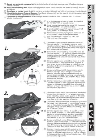
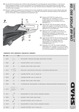
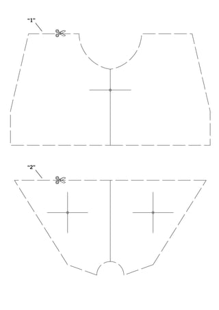
SlideShare ist ein Scribd-Unternehmen logo
1 von 4
Downloaden Sie, um offline zu lesen
Consejo para un correcto montaje del kit: No apretar los tornillos del todo hasta asegurarse que el KIT esté correctamente


                                                                                                                                                                 C0SP99ST
                                                                                                                                        CAN-AM SPYDER 990 ‘09
 colocado y alineado.
 Advice for correct fitting of the kit: Do not fully tighten the screws until it is ensured that the KIT is correctly attached
 and aligned.
 Conseil pour un montage correct du kit: Ne pas serrer les vis avant d’être sûr que le Kit est correctement monté et ajusté.
 Hinweis für einen korrekten Einbau des Bausatzes: Ziehen Sie die Schrauben nicht ganz fest, bevor Sie sich nicht vergewissert haben,
 daß der Bausatz korrekt eingestellt und ausgerichtet ist.
 Consiglio per un montaggio corretto del kit: Non stringere del tutto le viti finché non si è controllato che il Kit è situato e
 allineato correttamente.

                                                                   Si su moto ya posee de origen el soporte (A), el soporte
                                                                   KIT TOP C0SP99ST no se puede montar.
                                                                   If your motorcycle already has the support (A), the support
                                                                   KIT TOP C0SP99ST can not be assembled.
                                                       A
                                                                   Si la moto a déjà le support (A) original, le support KIT
                                                                   TOP C0SP99ST ne peut être pas monté.
                                                                   Wenn ihr fahrrad hat die ursprünglichen medien (A), KIT
                                                                   TOP C0SP99SF Träger nicht eingestellt werden.


                                                                                                                                                                KIT TOPMASTER
                                                                   Se la sua moto ha già il supporto (A), il KIT TOP
                                                                   C0SP99ST non si può montare.

                                                                   Desmontar la tapeta trasera (B) mediante el tornillo (C).
                                                                   Colocar la plantilla “1” en la tapeta, marcar el punto
                                                                   indicado y realizar un agujero de Ø22 (Nota: aconsejamos

1.                                                                 que se realicen varios agujeros de Ø inferior hasta llegar al
                                                                   Ø22, por seguridad del usuario).
                                                                   Dismantle the rear fairing (B) by means of the screw (C).
                                                           B       Place the template “1” on the fairing, make a mark on the
                                                                   indicated point and drill a Ø22 hole (Note: we suggest
                                                                   making first lower Ø holes until reaching a Ø of 22, for the
                                                                   user’s safety).
                                                                   Démonter la petite cache arrière (B) au moyen du vis (C).
                                                                   Placer la semelle“1” dans la petite cache, y signaler le
                                                                   point et faire un trou de Ø22 (Note: on conseille de faire
                                                           C       divers trous de Ø inferieurs jusqu’a arriver au Ø22, pour
                                                                   sécurité de l’usager).
                                                                   Schraub·verschlus zurück (B) disassemblieren, um die
                                               Ø 22                Schraube (C). Legen Sie die Vorlage "1" auf Schraub-
                                                                   verschlus, markieren Sie den angegebenen Punkt und
                                                                   machen Sie ein Loch Ø22. (Anmerkung: empfohlen wird,
                                                                   den eine Reihe von Löchern, bis der Boden Ø Ø22, für die
                                                                   Sicherheit der Benutzer).
                                                                   Smontare la carenatura posteriori (B) mediante le viti (C).
                      “1”                                          Collocare la sagoma “1” nella carenatura, segnare il punto
                                                                   indicato ed effettuare un buco Ø22 (Nota: si consiglia di
                                                                   effettuare vari buchi di Ø inferiore fino ad arrivare a Ø22,
                                                                   per la sicurezza degli utenti).


2.                                                                 Desmontar la tapeta inferior paso de rueda (D) mediante sus
                                                                   tornillos. Colocar la plantilla “2” en la tapeta, marcar los
                                                                   puntos indicados y realizar los dos agujeros de Ø24 (Nota:
                                                                   aconsejamos que se realicen varios agujeros de Ø inferior
                                                                   hasta llegar al Ø24, por seguridad del usuario).
                                                                   Disassemble the lower wheel arch moulding (D) by means of
                                                                   the screws. Place the template “2” on the fairing, make a
                                                                   mark on the indicated points and drill two Ø24 holes (Note:
                                                                   we suggest making first lower Ø holes until reaching a Ø of
                                                                   24, for the user’s safety).
                                                           D       Démonter la petite cache inferieur de roue (D) au moyen
                                                                   des vis. Placer la semelle “2” sur la petite cache pour y
                                                                   signaler les points indiquées et faire deux trous de Ø24
                                                                   (Note: on conseille de faire divers trous de Ø inferieur
                                                                   jusqu’à arriver au Ø24, pour sureté de l’usager).
                                                                   Schraub·verschlus als ein rad (D) disassemblieren, um die
                                    Ø 24                           Schraube. Legen Sie die Vorlage “2” auf Schraub·verschlus,
                                                                   markieren Sie den angegebenen Punkt und machen Sie Zwei
                                                                   Loch Ø24 (Anmerkung: empfohlen wird, den eine Reihe von
                                                                   Löchern, bis der Boden Ø Ø24, für die Sicherheit der Benutzer).
                                                                   Smontare il codolini passaruota (D) mediante le viti.
               “2”                                                 Collocare la sagoma “2” nella carenatura, segnare il punto
                                                                   indicato ed effettuare due buchi da Ø24 (Nota: si consiglia
                                                                   di effettuare vari buchi di Ø inferiore fino ad arrivare a Ø24,
                                                                   per la sicurezza degli utenti).
3.                                   Desmontar el asiento (E), soltar su amortiguador y quitar


                         C0SP99ST
CAN-AM SPYDER 990 ‘09                        E               G               los dos tornillos delanteros (F) y el central (G).
                                                                             Disassemble the seat (E), release its shock absorber and
                                                 F
                                                                             remove the two front screws (F) and the central screw (G).
                                                                             Démonter le siège (E), lâcher son amortisseur et enlever
                                                                             les deux vis avant (F) et central (G).
                                                                             Sitz Demontieren (E), halten Sie den Schock, und
                                                                             entfernen Sie die beiden Schrauben (F) und der vorderen
                                                                             Schraube (G).
                                                                             Smontare il sedile (E), liberare l’ammortizzatore e togliere
                                                                             le due viti frontale (F) e la vite centrale (G).


                                        4.   H
                        KIT TOPMASTER


                                                                             Desmontar la carcasa de los agarraderos laterales (H),
                                                                             montarle por la parte inferior el bulón roscado (1)
                                                                             mediante los tornillos (2) y arandelas (3).
                                                                             Disassemble the lateral grip casing (H), and assemble the
                                                                             threaded bolt through the inferior part of (1) by means of
                                                                             the screws (2) and washers (3).
                                                                             Démonter la carcasse sur les poignées latérales (H), et le
                                                                             monter dans la partie inferieur le boulon filetage (1) au
                                                                             moyen des vis (2) et rondelles (3).
                                                                             Entfernen Sie die seitliche Abdeckung der Handhabung
                                                                             (H), montiert an der Unterseite der Gewinde-Schraube (1)
                                                                             wie im Bild mit den Schrauben (2) und Scheiben (3).
                                                     1
                                                                             Smontare il rivestimento delle maniglie laterali (H),
                                                                             montare il perno filettato per la parte inferiore (1)
                                                     3
                                                                             mediante le viti (2) e le rondelle (3).
                                                     2


                                                                     5

                                                                         4
                                                                             Montar el refuerzo interior (4) mediante los tornillos (5).
                                        5.                                   Volver a montar la carcasa de los agarraderos laterales (H).
                                                                             Assemble the interior reinforcement (4) by means of the
                                                                             screws (5). Reassemble the lateral grip casings (H).
                                                                             Monter le renfort intérieur (4) au moyen des vis (5).
                                                                             Monter à nouveau la carcasse des poignées latérales (H).
                                                                             Setzen Sie die innere Verstärkung (4) wie im Bild mit den
                                                                             Schrauben (5). Die seitliche Abdeckung der Handhabung
                                                                             wieder anbringen (H).
                                                                             Montare il rafforzamento interiore (4) mediante le viti (5).
                                                                             Rimontare il rivestimento delle maniglie laterali (H).


                                                                             Montar el asiento (E) mediante los tornillos delanteros (F)

                                        6.   E               6
                                                                             y el tornillo central 6), que saldrá por la zona inferor
                                                                             donde lo fijaremos al bulón roscado (1) mediante la
                                                                             arandela (7) y tuerca (8). Volver a montar la tapeta trasera
                                                                             (B) mediante el tornillo (C). Volver a montar la tapeta
                                                 F                           inferior paso de rueda (D) mediante sus tornillos.
                                                                             Assemble the seat (E) by means of the front screws (F)
                                                                             and the central screw (6), which will come out through
                                                                             the inferior zone where it must by attached to the
                                                                             threaded bolt (1) by means of the washer (7) and the nut
                                                         1                   (8). Reassemble the back fairing (B) by means of the
                                                                             screws (C). Reassemble the lower wheel arch moulding
                                                                 7           (D) by means of the screws.
                                                                 8           Monter le siège (E) avec le vis avant (F) et le vis central
                                                                             (6), en sortant dans la zone inferieur ou on va fixer au
                                                                             boulon filetage (1) au moyen de la rondelle (7) et l’écrou
                                                                             (8). Monter à nouveau la petite cache arrière (B) au
                                                                             moyen de l’écrou (C). Monter à nouveau la petite cache
REF. 500479
                                                                             inferieur pas de roue (D) avec ses vis.
 Edición 1ª
Sie den Sitz (E) mintieren wie im Bild mit den Schrauben (F) und Schraube (6), wird der Bereich, in dem Sie die


                                                                                                                                                                                                C0SP99ST
                                                                                                                                                                       CAN-AM SPYDER 990 ‘09
       inferor Gewinde Schraube (1) durch die Scheibe (7) und Scraubenmutter (8). Die Schraub·verschlus das wieder
       anbringen (B) wie im bild mit den schrauben (C). Die unter Schraub·verschlus Radkasten wieder anbringen (D) wie
       im bild mit den schrauben.
       Montare il sedile (E) mediante le viti anteriore (F) e la vite centrale (6), la quale uscirà per la zona inferiore dove sarà
       fissata al perno filettato (1) mediante le rondelle (7) e il dado (8). Rimontare la carenatura posteriori (B) mediante la
       vite (C). Rimontare il codolini passaruota (D) mediante le vite.


                                                                                                       Colocar el KIT TOP (9) y fijarlo con el
                                                                                                       distanciador (10), arandela (11) y tornillo (12) en
                                                     12                                                la parte superior y en la inferior con los
7.                                                    11                           9                   distanciadotes (13), los tornillos (14) y las
                                                                                                       arandelas (11).
                                                                                                       Place the KIT TOP (9) and fasten it with the
                                                                                                       spacer (10), washer (11) and screw (12) on the
                                                                                                       upper part and the spacers (13), screws (14) and


                                                                                                                                                                                               KIT TOPMASTER
                                                                                                       washers (11) on the lower part.
                                                     10
                                                                                                       Placer le KIT TOP (9) pour le fixer avec le
                                                                                                       détendeur (10), la rondelle (11) et le vis (12)
                                                                                                       dans la partie supérieure, et dans la zone
                                                                                                       inferieure avec les détendeurs (13), les vis (14)
                                                             13                                        et des rondelles (11).
                                                             11                                        Legen Sie die TOP KIT (9) und fixierung mit den
                                                                                                       Abstandhalter (10), Scheibe (11) und Schraube
                                                             14                                        (12) am oberen und unteren Rand mit
                                                                                                       Abstanhalter (13), Schrauben (14) und
                                                                                                       Unterlegscheiben (11).
                                                                                                       Collocare el KIT TOP (9) e fissarlo mediante i
                                                                                                       distanziatori (10), rondelle (11) e viti (12) nella
                                                                                                       zona superiore, e mediante i distanziatori (13), le
                                                                                                       viti (14) e le rondelle (11) nella zona inferiore.


COMPONENTES / PARTS / COMPOSANTES / EINZELBAUTEILE / COMPONENTI:

Pos.    Ref.                   Cant.

 1     261211                   1      Bulón roscado M8 - Threaded bolt - Boulon filetage - Gewinde Schraube - Perno filettato


 2     304057                   2      Tornillo M6 x 25 DIN 912 - Screw - Vis - Schraube - Vite


 3     303017                   2      Arandela Ø6 - Washer - Rondelle - Scheibe - Rondella


 4     261212                   1      Refuerzo interior - Interior reinforcement - Renfort intérieur - Innere Verstärkung - Rafforzamento interiore


 5     304104                   2      Tornillo M8 x 25 DIN 7991 - Screw - Vis - Schraube - Vite


 6     304169                   1      Tornillo M8 x 50 DIN 7380 - Screw - Vis - Schraube - Vite


 7     303020                   1      Arandela Ø8 - Washer - Rondelle - Scheibe - Rondella


 8     302024                   1      Tuerca M8 autoblocante - Self-blocking Nut M8 - Écrou M8 autobloquant - Selbstanziehende Mutter M8 - Bullone M8 autobloccante


 9     261213                   1      KIT TOP


10     261217                   1      Distanciador Ø18 Ø11 x 43 - Spacer - Entre-toise - Abstandshalter - Distanziatore


11     303025                   3      Arandela Ø10 - Washer - Rondelle - Scheibe - Rondella


12     261218                   1      Tornillo M10 x 70 DIN 7380 - Screw - Vis - Schraube - Vite


13     261219                   2      Distanciador Ø20 Ø11 x 13 - Spacer - Entre-toise - Abstandshalter - Distanziatore


14     304223                   2      Tornillo M10 x 35 DIN 7380 - Screw - Vis - Schraube - Vite                                                                      REF. 500479
                                                                                                                                                                        Edición 1ª
“1”

      ✄


“2”

      ✄

Weitere ähnliche Inhalte

Empfohlen

2024 State of Marketing Report – by Hubspot
2024 State of Marketing Report – by Hubspot2024 State of Marketing Report – by Hubspot
2024 State of Marketing Report – by HubspotMarius Sescu
 
Everything You Need To Know About ChatGPT
Everything You Need To Know About ChatGPTEverything You Need To Know About ChatGPT
Everything You Need To Know About ChatGPTExpeed Software
 
Product Design Trends in 2024 | Teenage Engineerings
Product Design Trends in 2024 | Teenage EngineeringsProduct Design Trends in 2024 | Teenage Engineerings
Product Design Trends in 2024 | Teenage EngineeringsPixeldarts
 
How Race, Age and Gender Shape Attitudes Towards Mental Health
How Race, Age and Gender Shape Attitudes Towards Mental HealthHow Race, Age and Gender Shape Attitudes Towards Mental Health
How Race, Age and Gender Shape Attitudes Towards Mental HealthThinkNow
 
AI Trends in Creative Operations 2024 by Artwork Flow.pdf
AI Trends in Creative Operations 2024 by Artwork Flow.pdfAI Trends in Creative Operations 2024 by Artwork Flow.pdf
AI Trends in Creative Operations 2024 by Artwork Flow.pdfmarketingartwork
 
PEPSICO Presentation to CAGNY Conference Feb 2024
PEPSICO Presentation to CAGNY Conference Feb 2024PEPSICO Presentation to CAGNY Conference Feb 2024
PEPSICO Presentation to CAGNY Conference Feb 2024Neil Kimberley
 
Content Methodology: A Best Practices Report (Webinar)
Content Methodology: A Best Practices Report (Webinar)Content Methodology: A Best Practices Report (Webinar)
Content Methodology: A Best Practices Report (Webinar)contently
 
How to Prepare For a Successful Job Search for 2024
How to Prepare For a Successful Job Search for 2024How to Prepare For a Successful Job Search for 2024
How to Prepare For a Successful Job Search for 2024Albert Qian
 
Social Media Marketing Trends 2024 // The Global Indie Insights
Social Media Marketing Trends 2024 // The Global Indie InsightsSocial Media Marketing Trends 2024 // The Global Indie Insights
Social Media Marketing Trends 2024 // The Global Indie InsightsKurio // The Social Media Age(ncy)
 
Trends In Paid Search: Navigating The Digital Landscape In 2024
Trends In Paid Search: Navigating The Digital Landscape In 2024Trends In Paid Search: Navigating The Digital Landscape In 2024
Trends In Paid Search: Navigating The Digital Landscape In 2024Search Engine Journal
 
5 Public speaking tips from TED - Visualized summary
5 Public speaking tips from TED - Visualized summary5 Public speaking tips from TED - Visualized summary
5 Public speaking tips from TED - Visualized summarySpeakerHub
 
ChatGPT and the Future of Work - Clark Boyd
ChatGPT and the Future of Work - Clark Boyd ChatGPT and the Future of Work - Clark Boyd
ChatGPT and the Future of Work - Clark Boyd Clark Boyd
 
Getting into the tech field. what next
Getting into the tech field. what next Getting into the tech field. what next
Getting into the tech field. what next Tessa Mero
 
Google's Just Not That Into You: Understanding Core Updates & Search Intent
Google's Just Not That Into You: Understanding Core Updates & Search IntentGoogle's Just Not That Into You: Understanding Core Updates & Search Intent
Google's Just Not That Into You: Understanding Core Updates & Search IntentLily Ray
 
Time Management & Productivity - Best Practices
Time Management & Productivity -  Best PracticesTime Management & Productivity -  Best Practices
Time Management & Productivity - Best PracticesVit Horky
 
The six step guide to practical project management
The six step guide to practical project managementThe six step guide to practical project management
The six step guide to practical project managementMindGenius
 
Beginners Guide to TikTok for Search - Rachel Pearson - We are Tilt __ Bright...
Beginners Guide to TikTok for Search - Rachel Pearson - We are Tilt __ Bright...Beginners Guide to TikTok for Search - Rachel Pearson - We are Tilt __ Bright...
Beginners Guide to TikTok for Search - Rachel Pearson - We are Tilt __ Bright...RachelPearson36
 

Empfohlen (20)

2024 State of Marketing Report – by Hubspot
2024 State of Marketing Report – by Hubspot2024 State of Marketing Report – by Hubspot
2024 State of Marketing Report – by Hubspot
 
Everything You Need To Know About ChatGPT
Everything You Need To Know About ChatGPTEverything You Need To Know About ChatGPT
Everything You Need To Know About ChatGPT
 
Product Design Trends in 2024 | Teenage Engineerings
Product Design Trends in 2024 | Teenage EngineeringsProduct Design Trends in 2024 | Teenage Engineerings
Product Design Trends in 2024 | Teenage Engineerings
 
How Race, Age and Gender Shape Attitudes Towards Mental Health
How Race, Age and Gender Shape Attitudes Towards Mental HealthHow Race, Age and Gender Shape Attitudes Towards Mental Health
How Race, Age and Gender Shape Attitudes Towards Mental Health
 
AI Trends in Creative Operations 2024 by Artwork Flow.pdf
AI Trends in Creative Operations 2024 by Artwork Flow.pdfAI Trends in Creative Operations 2024 by Artwork Flow.pdf
AI Trends in Creative Operations 2024 by Artwork Flow.pdf
 
Skeleton Culture Code
Skeleton Culture CodeSkeleton Culture Code
Skeleton Culture Code
 
PEPSICO Presentation to CAGNY Conference Feb 2024
PEPSICO Presentation to CAGNY Conference Feb 2024PEPSICO Presentation to CAGNY Conference Feb 2024
PEPSICO Presentation to CAGNY Conference Feb 2024
 
Content Methodology: A Best Practices Report (Webinar)
Content Methodology: A Best Practices Report (Webinar)Content Methodology: A Best Practices Report (Webinar)
Content Methodology: A Best Practices Report (Webinar)
 
How to Prepare For a Successful Job Search for 2024
How to Prepare For a Successful Job Search for 2024How to Prepare For a Successful Job Search for 2024
How to Prepare For a Successful Job Search for 2024
 
Social Media Marketing Trends 2024 // The Global Indie Insights
Social Media Marketing Trends 2024 // The Global Indie InsightsSocial Media Marketing Trends 2024 // The Global Indie Insights
Social Media Marketing Trends 2024 // The Global Indie Insights
 
Trends In Paid Search: Navigating The Digital Landscape In 2024
Trends In Paid Search: Navigating The Digital Landscape In 2024Trends In Paid Search: Navigating The Digital Landscape In 2024
Trends In Paid Search: Navigating The Digital Landscape In 2024
 
5 Public speaking tips from TED - Visualized summary
5 Public speaking tips from TED - Visualized summary5 Public speaking tips from TED - Visualized summary
5 Public speaking tips from TED - Visualized summary
 
ChatGPT and the Future of Work - Clark Boyd
ChatGPT and the Future of Work - Clark Boyd ChatGPT and the Future of Work - Clark Boyd
ChatGPT and the Future of Work - Clark Boyd
 
Getting into the tech field. what next
Getting into the tech field. what next Getting into the tech field. what next
Getting into the tech field. what next
 
Google's Just Not That Into You: Understanding Core Updates & Search Intent
Google's Just Not That Into You: Understanding Core Updates & Search IntentGoogle's Just Not That Into You: Understanding Core Updates & Search Intent
Google's Just Not That Into You: Understanding Core Updates & Search Intent
 
How to have difficult conversations
How to have difficult conversations How to have difficult conversations
How to have difficult conversations
 
Introduction to Data Science
Introduction to Data ScienceIntroduction to Data Science
Introduction to Data Science
 
Time Management & Productivity - Best Practices
Time Management & Productivity -  Best PracticesTime Management & Productivity -  Best Practices
Time Management & Productivity - Best Practices
 
The six step guide to practical project management
The six step guide to practical project managementThe six step guide to practical project management
The six step guide to practical project management
 
Beginners Guide to TikTok for Search - Rachel Pearson - We are Tilt __ Bright...
Beginners Guide to TikTok for Search - Rachel Pearson - We are Tilt __ Bright...Beginners Guide to TikTok for Search - Rachel Pearson - We are Tilt __ Bright...
Beginners Guide to TikTok for Search - Rachel Pearson - We are Tilt __ Bright...
 

Can Am Spyder Top

  • 1. Consejo para un correcto montaje del kit: No apretar los tornillos del todo hasta asegurarse que el KIT esté correctamente C0SP99ST CAN-AM SPYDER 990 ‘09 colocado y alineado. Advice for correct fitting of the kit: Do not fully tighten the screws until it is ensured that the KIT is correctly attached and aligned. Conseil pour un montage correct du kit: Ne pas serrer les vis avant d’être sûr que le Kit est correctement monté et ajusté. Hinweis für einen korrekten Einbau des Bausatzes: Ziehen Sie die Schrauben nicht ganz fest, bevor Sie sich nicht vergewissert haben, daß der Bausatz korrekt eingestellt und ausgerichtet ist. Consiglio per un montaggio corretto del kit: Non stringere del tutto le viti finché non si è controllato che il Kit è situato e allineato correttamente. Si su moto ya posee de origen el soporte (A), el soporte KIT TOP C0SP99ST no se puede montar. If your motorcycle already has the support (A), the support KIT TOP C0SP99ST can not be assembled. A Si la moto a déjà le support (A) original, le support KIT TOP C0SP99ST ne peut être pas monté. Wenn ihr fahrrad hat die ursprünglichen medien (A), KIT TOP C0SP99SF Träger nicht eingestellt werden. KIT TOPMASTER Se la sua moto ha già il supporto (A), il KIT TOP C0SP99ST non si può montare. Desmontar la tapeta trasera (B) mediante el tornillo (C). Colocar la plantilla “1” en la tapeta, marcar el punto indicado y realizar un agujero de Ø22 (Nota: aconsejamos 1. que se realicen varios agujeros de Ø inferior hasta llegar al Ø22, por seguridad del usuario). Dismantle the rear fairing (B) by means of the screw (C). B Place the template “1” on the fairing, make a mark on the indicated point and drill a Ø22 hole (Note: we suggest making first lower Ø holes until reaching a Ø of 22, for the user’s safety). Démonter la petite cache arrière (B) au moyen du vis (C). Placer la semelle“1” dans la petite cache, y signaler le point et faire un trou de Ø22 (Note: on conseille de faire C divers trous de Ø inferieurs jusqu’a arriver au Ø22, pour sécurité de l’usager). Schraub·verschlus zurück (B) disassemblieren, um die Ø 22 Schraube (C). Legen Sie die Vorlage "1" auf Schraub- verschlus, markieren Sie den angegebenen Punkt und machen Sie ein Loch Ø22. (Anmerkung: empfohlen wird, den eine Reihe von Löchern, bis der Boden Ø Ø22, für die Sicherheit der Benutzer). Smontare la carenatura posteriori (B) mediante le viti (C). “1” Collocare la sagoma “1” nella carenatura, segnare il punto indicato ed effettuare un buco Ø22 (Nota: si consiglia di effettuare vari buchi di Ø inferiore fino ad arrivare a Ø22, per la sicurezza degli utenti). 2. Desmontar la tapeta inferior paso de rueda (D) mediante sus tornillos. Colocar la plantilla “2” en la tapeta, marcar los puntos indicados y realizar los dos agujeros de Ø24 (Nota: aconsejamos que se realicen varios agujeros de Ø inferior hasta llegar al Ø24, por seguridad del usuario). Disassemble the lower wheel arch moulding (D) by means of the screws. Place the template “2” on the fairing, make a mark on the indicated points and drill two Ø24 holes (Note: we suggest making first lower Ø holes until reaching a Ø of 24, for the user’s safety). D Démonter la petite cache inferieur de roue (D) au moyen des vis. Placer la semelle “2” sur la petite cache pour y signaler les points indiquées et faire deux trous de Ø24 (Note: on conseille de faire divers trous de Ø inferieur jusqu’à arriver au Ø24, pour sureté de l’usager). Schraub·verschlus als ein rad (D) disassemblieren, um die Ø 24 Schraube. Legen Sie die Vorlage “2” auf Schraub·verschlus, markieren Sie den angegebenen Punkt und machen Sie Zwei Loch Ø24 (Anmerkung: empfohlen wird, den eine Reihe von Löchern, bis der Boden Ø Ø24, für die Sicherheit der Benutzer). Smontare il codolini passaruota (D) mediante le viti. “2” Collocare la sagoma “2” nella carenatura, segnare il punto indicato ed effettuare due buchi da Ø24 (Nota: si consiglia di effettuare vari buchi di Ø inferiore fino ad arrivare a Ø24, per la sicurezza degli utenti).
  • 2. 3. Desmontar el asiento (E), soltar su amortiguador y quitar C0SP99ST CAN-AM SPYDER 990 ‘09 E G los dos tornillos delanteros (F) y el central (G). Disassemble the seat (E), release its shock absorber and F remove the two front screws (F) and the central screw (G). Démonter le siège (E), lâcher son amortisseur et enlever les deux vis avant (F) et central (G). Sitz Demontieren (E), halten Sie den Schock, und entfernen Sie die beiden Schrauben (F) und der vorderen Schraube (G). Smontare il sedile (E), liberare l’ammortizzatore e togliere le due viti frontale (F) e la vite centrale (G). 4. H KIT TOPMASTER Desmontar la carcasa de los agarraderos laterales (H), montarle por la parte inferior el bulón roscado (1) mediante los tornillos (2) y arandelas (3). Disassemble the lateral grip casing (H), and assemble the threaded bolt through the inferior part of (1) by means of the screws (2) and washers (3). Démonter la carcasse sur les poignées latérales (H), et le monter dans la partie inferieur le boulon filetage (1) au moyen des vis (2) et rondelles (3). Entfernen Sie die seitliche Abdeckung der Handhabung (H), montiert an der Unterseite der Gewinde-Schraube (1) wie im Bild mit den Schrauben (2) und Scheiben (3). 1 Smontare il rivestimento delle maniglie laterali (H), montare il perno filettato per la parte inferiore (1) 3 mediante le viti (2) e le rondelle (3). 2 5 4 Montar el refuerzo interior (4) mediante los tornillos (5). 5. Volver a montar la carcasa de los agarraderos laterales (H). Assemble the interior reinforcement (4) by means of the screws (5). Reassemble the lateral grip casings (H). Monter le renfort intérieur (4) au moyen des vis (5). Monter à nouveau la carcasse des poignées latérales (H). Setzen Sie die innere Verstärkung (4) wie im Bild mit den Schrauben (5). Die seitliche Abdeckung der Handhabung wieder anbringen (H). Montare il rafforzamento interiore (4) mediante le viti (5). Rimontare il rivestimento delle maniglie laterali (H). Montar el asiento (E) mediante los tornillos delanteros (F) 6. E 6 y el tornillo central 6), que saldrá por la zona inferor donde lo fijaremos al bulón roscado (1) mediante la arandela (7) y tuerca (8). Volver a montar la tapeta trasera (B) mediante el tornillo (C). Volver a montar la tapeta F inferior paso de rueda (D) mediante sus tornillos. Assemble the seat (E) by means of the front screws (F) and the central screw (6), which will come out through the inferior zone where it must by attached to the threaded bolt (1) by means of the washer (7) and the nut 1 (8). Reassemble the back fairing (B) by means of the screws (C). Reassemble the lower wheel arch moulding 7 (D) by means of the screws. 8 Monter le siège (E) avec le vis avant (F) et le vis central (6), en sortant dans la zone inferieur ou on va fixer au boulon filetage (1) au moyen de la rondelle (7) et l’écrou (8). Monter à nouveau la petite cache arrière (B) au moyen de l’écrou (C). Monter à nouveau la petite cache REF. 500479 inferieur pas de roue (D) avec ses vis. Edición 1ª
  • 3. Sie den Sitz (E) mintieren wie im Bild mit den Schrauben (F) und Schraube (6), wird der Bereich, in dem Sie die C0SP99ST CAN-AM SPYDER 990 ‘09 inferor Gewinde Schraube (1) durch die Scheibe (7) und Scraubenmutter (8). Die Schraub·verschlus das wieder anbringen (B) wie im bild mit den schrauben (C). Die unter Schraub·verschlus Radkasten wieder anbringen (D) wie im bild mit den schrauben. Montare il sedile (E) mediante le viti anteriore (F) e la vite centrale (6), la quale uscirà per la zona inferiore dove sarà fissata al perno filettato (1) mediante le rondelle (7) e il dado (8). Rimontare la carenatura posteriori (B) mediante la vite (C). Rimontare il codolini passaruota (D) mediante le vite. Colocar el KIT TOP (9) y fijarlo con el distanciador (10), arandela (11) y tornillo (12) en 12 la parte superior y en la inferior con los 7. 11 9 distanciadotes (13), los tornillos (14) y las arandelas (11). Place the KIT TOP (9) and fasten it with the spacer (10), washer (11) and screw (12) on the upper part and the spacers (13), screws (14) and KIT TOPMASTER washers (11) on the lower part. 10 Placer le KIT TOP (9) pour le fixer avec le détendeur (10), la rondelle (11) et le vis (12) dans la partie supérieure, et dans la zone inferieure avec les détendeurs (13), les vis (14) 13 et des rondelles (11). 11 Legen Sie die TOP KIT (9) und fixierung mit den Abstandhalter (10), Scheibe (11) und Schraube 14 (12) am oberen und unteren Rand mit Abstanhalter (13), Schrauben (14) und Unterlegscheiben (11). Collocare el KIT TOP (9) e fissarlo mediante i distanziatori (10), rondelle (11) e viti (12) nella zona superiore, e mediante i distanziatori (13), le viti (14) e le rondelle (11) nella zona inferiore. COMPONENTES / PARTS / COMPOSANTES / EINZELBAUTEILE / COMPONENTI: Pos. Ref. Cant. 1 261211 1 Bulón roscado M8 - Threaded bolt - Boulon filetage - Gewinde Schraube - Perno filettato 2 304057 2 Tornillo M6 x 25 DIN 912 - Screw - Vis - Schraube - Vite 3 303017 2 Arandela Ø6 - Washer - Rondelle - Scheibe - Rondella 4 261212 1 Refuerzo interior - Interior reinforcement - Renfort intérieur - Innere Verstärkung - Rafforzamento interiore 5 304104 2 Tornillo M8 x 25 DIN 7991 - Screw - Vis - Schraube - Vite 6 304169 1 Tornillo M8 x 50 DIN 7380 - Screw - Vis - Schraube - Vite 7 303020 1 Arandela Ø8 - Washer - Rondelle - Scheibe - Rondella 8 302024 1 Tuerca M8 autoblocante - Self-blocking Nut M8 - Écrou M8 autobloquant - Selbstanziehende Mutter M8 - Bullone M8 autobloccante 9 261213 1 KIT TOP 10 261217 1 Distanciador Ø18 Ø11 x 43 - Spacer - Entre-toise - Abstandshalter - Distanziatore 11 303025 3 Arandela Ø10 - Washer - Rondelle - Scheibe - Rondella 12 261218 1 Tornillo M10 x 70 DIN 7380 - Screw - Vis - Schraube - Vite 13 261219 2 Distanciador Ø20 Ø11 x 13 - Spacer - Entre-toise - Abstandshalter - Distanziatore 14 304223 2 Tornillo M10 x 35 DIN 7380 - Screw - Vis - Schraube - Vite REF. 500479 Edición 1ª
  • 4. “1” ✄ “2” ✄