
Empfohlen
Weitere ähnliche Inhalte
Was ist angesagt?
Was ist angesagt? (20)
Andere mochten auch
Andere mochten auch (20)
Ähnlich wie Cogeneration
Ähnlich wie Cogeneration (20)
Mehr von skdass23
Kürzlich hochgeladen
Kürzlich hochgeladen (20)
Cogeneration
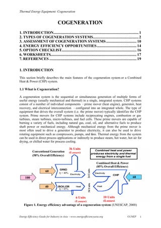
- 1. Thermal Energy Equipment: Cogeneration Energy Efficiency Guide for Industry in Asia –www.energyefficiencyasia.org ©UNEP 1 COGENERATION 1. INTRODUCTION.................................................................................... 1 2. TYPES OF COGENERATION SYSTEMS............................................. 2 3. ASSESSMENT OF COGENERATION SYSTEMS.............................. 10 4. ENERGY EFFICIENCY OPPORTUNITIES....................................... 14 5. OPTION CHECKLIST.......................................................................... 16 6. WORKSHEETS..................................................................................... 17 7. REFERENCES ...................................................................................... 19 1. INTRODUCTION This section briefly describes the main features of the cogeneration system or a Combined Heat & Power (CHP) system. 1.1 What is Cogeneration? A cogeneration system is the sequential or simultaneous generation of multiple forms of useful energy (usually mechanical and thermal) in a single, integrated system. CHP systems consist of a number of individual components –prime mover (heat engine), generator, heat recovery, and electrical interconnection –configured into an integrated whole. The type of equipment that drives the overall system (i.e. the prime mover) typically identifies the CHP system. Prime movers for CHP systems include reciprocating engines, combustion or gas turbines, steam turbines, micro-turbines, and fuel cells. These prime movers are capable of burning a variety of fuels, including natural gas, coal, oil, and alternative fuels to produce shaft power or mechanical energy. Although mechanical energy from the prime mover is most often used to drive a generator to produce electricity, it can also be used to drive rotating equipment such as compressors, pumps, and fans. Thermal energy from the system can be used in direct process applications or indirectly to produce steam, hot water, hot air for drying, or chilled water for process cooling. Figure 1. Energy efficiency advantage of a cogeneration system (UNESCAP, 2000) 100 68 24Units34Units 6 Units (Losses) 60 40 36 Units (Losses) η = 85% η = 40% 10 Units (Losses) Conventional Generation (58% Overall Efficiency) Combined Heat & Power (85% Overall Efficiency)
- 2. Thermal Energy Equipment: Cogeneration Energy Efficiency Guide for Industry in Asia –www.energyefficiencyasia.org ©UNEP 2 Figure 1 shows the efficiency advantage of CHP compared to the conventional central station power generation and on-site boilers. When both thermal and electrical processes are compared, a CHP system typically requires only three-fourth the primary energy compared to separate heat and power systems. This reduced primary fuel consumption is the main environmental benefit of CHP, since burning the same amount of fuel more efficiently means fewer emissions for the same level of output. 1.2 The Benefits of Cogeneration Provided the cogeneration is optimized in the way described above (i.e. sized according to the heat demand), the following benefits can be obtained: § Increased efficiency of energy conversion and use § Lower emissions to the environment, in particular of CO2, the main greenhouse gas § In some cases, biomass fuels and some waste materials such as refinery gases, process or agricultural waste (either anaerobically digested or gasified), are used. These substances which serve as fuels for cogeneration schemes, increases the cost-effectiveness and reduces the need for waste disposal § Large cost savings, providing additional competitiveness for industrial and commercial users while offering affordable heat for domestic users also § An opportunity to move towards more decentralized forms of electricity generation, where plants are designed to meet the needs of local consumers, providing high efficiency, avoiding transmission losses and increasing flexibility in system use. This will particularly be the case if natural gas is the energy carrier § An opportunity to increase the diversity of generation plant, and provide competition in generation. Cogeneration provides one of the most important vehicles for promoting liberalization in energy markets. 2. TYPES OF COGENERATION SYSTEMS This section includes various types of cogeneration systems: steam turbine cogeneration system, gas turbine cogeneration system, and reciprocating engine cogeneration system. It also includes a classification of cogeneration systems on the basis of the sequence of energy used. 2.1 Steam Turbine Cogeneration System Steam turbines are one of the most versatile and oldest prime mover technologies still in general production. Power generation using steam turbines has been in use for about 100 years, when they replaced reciprocating steam engines due to their higher efficiencies and lower costs. The capacity of steam turbines can range from 50 kW to several hundred MWs for large utility power plants. Steam turbines are widely used for combined heat and power (CHP) applications. The thermodynamic cycle for the steam turbine is the Rankine cycle. The cycle is the basis for conventional power generating stations and consists of a heat source (boiler) that converts water to high-pressure steam. In the steam cycle, water is first pumped to medium to high pressure. It is then heated to the boiling temperature corresponding to the pressure, boiled (heated from liquid to vapor), and then most frequently superheated (heated to a temperature above that of boiling). A multistage turbine expands the pressurized steam to lower pressure and the steam is then exhausted either to a condenser at vacuum conditions or into an intermediate temperature steam distribution system that delivers the steam to the
- 3. Thermal Energy Equipment: Cogeneration Energy Efficiency Guide for Industry in Asia –www.energyefficiencyasia.org ©UNEP 3 Boiler Fuel Turbine Process HP Steam LP Steam Condensate industrial or commercial application. The condensate from the condenser or from the steam utilization system returns to the feedwater pump for continuation of the cycle. The two types of steam turbines most widely used are the backpressure and the extraction- condensing types. The choice between backpressure turbine and extraction-condensing turbine depends mainly on the quantities of power and heat, quality of heat, and economic factors. The extraction points of steam from the turbine could be more than one, depending on the temperature levels of heat required by the processes. 2.1.1 Back Pressure Steam Turbine A back pressure steam turbine is the simplest configuration. Steam exits the turbine at a pressure higher or at least equal to the atmospheric pressure, which depends on the needs of the thermal load. This is why the term back- pressure is used. It is also possible to extract steam from intermediate stages of the steam turbine, at a pressure and temperature appropriate for the thermal load. After the exit from the turbine, the steam is fed to the load, where it releases heat and is condensed. The condensate returns to the system with a flow rate which can be lower than the steam flow rate, if steam mass is used in the process or if there are losses along the piping. Make-up water retains the mass balance. The back - pressure system has the following advantages: § Simple configuration with few components. § The costs of expensive low-pressure stages of the turbine are avoided. § Low capital cost. § Reduced or even no need of cooling water. § High total efficiency, because there is no heat rejection to the environment through condenser. Figure 2. Back Pressure Steam Turbine
- 4. Thermal Energy Equipment: Cogeneration Energy Efficiency Guide for Industry in Asia –www.energyefficiencyasia.org ©UNEP 4 The back - pressure system has the following disadvantages: § The steam turbine is larger for the same power output, because it operates under a lower enthalpy difference of steam. § The steam mass flow rate through the turbine depends on the thermal load. Consequently, the electricity generated by the steam is controlled by the thermal load, which results in little or no flexibility in directly matching electrical output to electrical load. Therefore, there is a need for a two-way connection to the grid for purchasing supplemental electricity or selling excess electricity generated. Increased electricity production is possible by venting steam directly to the atmosphere, but this is very inefficient. It results in a waste of treated boiler water and, most likely, in poor economical as well as energetic performances. 2.1.2 Extraction Condensing Steam Turbine In such a system, steam for the thermal load is obtained by extraction from one or more intermediate stages at the appropriate pressure and temperature. The remaining steam is exhausted to the pressure of the condenser, which can be as low as 0.05 bar with a corresponding condensing temperature of about 33°C. It is rather improbable that such low temperature heat finds useful applications. Consequently, it is rejected to the environment. In comparison to the back - pressure system, the condensing type turbine has a higher capital cost and, in general, a lower total efficiency. However, to a certain extent, it can control the electrical power independent of the thermal load by proper regulation of the steam flow rate through the turbine. Figure 3. Extraction Condensing Steam Turbine Boiler Fuel Turbine Process HP Steam LP Steam Condensate Condenser
- 5. Thermal Energy Equipment: Cogeneration Energy Efficiency Guide for Industry in Asia –www.energyefficiencyasia.org ©UNEP 5 2.2 Gas Turbine Cogeneration System Gas turbine systems operate on the thermodynamic cycle known as the Brayton cycle. In a Brayton cycle, atmospheric air is compressed, heated, and then expanded, with the excess of power produced by the turbine or expander over that consumed by the compressor used for power generation. Gas turbine cogeneration systems can produce all or a part of the energy requirement of the site, and the energy released at high temperature in the exhaust stack can be recovered for various heating and cooling applications (see Figure 4). Though natural gas is most commonly used, other fuels such as light fuel oil or diesel can also be employed. The typical range of gas turbines varies from a fraction of a MW to around 100 MW. Gas turbine cogeneration has probably experienced the most rapid development in recent years due to the greater availability of natural gas, rapid progress in the technology, significant reduction in installation costs, and better environmental performance. Furthermore, the gestation period for developing a project is shorter and the equipment can be delivered in a modular manner. Gas turbines have a short start-up time and provide the flexibility of intermittent operation. Though they have a low heat to power conversion efficiency, more heat can be recovered at higher temperatures. If the heat output is less than that required by the user, it is possible to have supplementary natural gas firing by mixing additional fuel to the oxygen-rich exhaust gas to boost the thermal output more efficiently. 2.2.1 Open-cycle gas turbine cogeneration systems Most of the currently available gas turbine systems, in any sector of applications, operate on the open Brayton (also called Joule cycle when irreversibilities are ignored) cycle where a compressor takes in air from the atmosphere and derives it at increased pressure to the combustor. The air temperature is also increased due to compression. Older and smaller units operate at a pressure ratio in the range of 15:1, while the newer and larger units operate at pressure ratios approaching 30:1. G Compressor Turbine HRSG Combustor Fuel Air Generator Exhaust Gases Condensate from Process Steam to Process Figure 4. Open Cycle Gas Turbine Cogeneration system
- 6. Thermal Energy Equipment: Cogeneration Energy Efficiency Guide for Industry in Asia –www.energyefficiencyasia.org ©UNEP 6 The air is delivered through a diffuser to a constant-pressure combustion chamber, where fuel is injected and burned. The diffuser reduces the air velocity to values acceptable in the combustor. There is a pressure drop across the combustor in the range of 1.2%. Combustion takes place with high excess air. The exhaust gases exit the combustor at high temperature and with oxygen concentrations of up to 15-16%. The highest temperature of the cycle appears at this point; the higher this temperature is, the higher the cycle efficiency is. The upper limit is placed by the temperature the materials of the gas turbine can withstand, as well as by the efficiency of the cooling blades. With current technology this is about 1300°C. The high pressure and temperature exhaust gases enter the gas turbine producing mechanical work to drive the compressor and the load (e.g. electric generator). The exhaust gases leave the turbine at a considerable temperature (450-600°C), which makes high-temperature heat recovery ideal. This is affected by a heat recovery boiler of single-pressure or double- pressure, for more efficient recovery of heat. The steam produced can have high pressure and temperature, which makes it appropriate not only for thermal processes but also for driving a steam turbine thus producing additional power. 2.2.2 Closed-cycle gas turbine cogeneration systems In the closed-cycle system, the working fluid (usually helium or air) circulates in a closed circuit. It is heated in a heat exchanger before entering the turbine, and it is cooled down after the exit of the turbine releasing useful heat. Thus, the working fluid remains clean and it does not cause corrosion or erosion. Heat Source G Compressor Turbine Generator Condensate from Process Steam to Process Heat Exchanger Figure 5: Closed Cycle Gas Turbine Cogeneration system
- 7. Thermal Energy Equipment: Cogeneration Energy Efficiency Guide for Industry in Asia –www.energyefficiencyasia.org ©UNEP 7 Source of heat can be the external combustion of any fuel. Also, nuclear energy or solar energy can be used. 2.3 Reciprocating Engine Cogeneration System Reciprocating engines are well suited to a variety of distributed generation applications, industrial, commercial, and institutional facilities for power generation and CHP. Reciprocating engines start quickly, follow load well, have good part-load efficiencies, and generally have high reliabilities. In many cases, multiple reciprocating engine units further increase overall plant capacity and availability. Reciprocating engines have higher electrical efficiencies than gas turbines of comparable size, and thus lower fuel-related operating costs. In addition, the first costs of reciprocating engine gensets are generally lower than gas turbine gensets up to 3-5 MW in size. Reciprocating engine maintenance costs are generally higher than comparable gas turbines, but the maintenance can often be handled by in-house staff or provided by local service organizations. Potential distributed generation applications for reciprocating engines include standby, peak shaving, grid support, and CHP applications in which hot water, low-pressure steam, or waste heat- fired absorption chillers are required. Reciprocating engines are also used extensively as direct mechanical drives in applications such as water pumping, air and gas compression and chilling/refrigeration. While the use of reciprocating engines is expected to grow in various distributed generation applications, the most prevalent on-site generation application for natural gas SI engines has traditionally been CHP, and this trend is likely to continue. The economics of natural gas engines in on-site generation applications is enhanced by effective use of the thermal energy contained in the exhaust gas and cooling systems, which generally represents 60 to 70% of the inlet fuel energy. There are four sources of usable waste heat from a reciprocating engine: exhaust gas, engine jacket-cooling water, lube oil cooling water, and turbocharger cooling. Recovered heat is generally in the form of hot water or low-pressure steam (<30 psig). The high temperature exhaust can generate medium pressure steam (up to about 150 psig), but the hot exhaust gas contains only about one half of the available thermal energy from a reciprocating engine. Figure 6: Reciprocating Engine Cogeneration System (UNESCAP, 2000)
- 8. Thermal Energy Equipment: Cogeneration Energy Efficiency Guide for Industry in Asia –www.energyefficiencyasia.org ©UNEP 8 Some industrial CHP applications use the engine exhaust gas directly for process drying. Generally, the hot water and low pressure steam produced by reciprocating engine CHP systems is appropriate for low temperature process needs, space heating, potable water heating, and to drive absorption chillers providing cold water, air conditioning, or refrigeration. Table 1. Typical cogeneration performance parameters (adapted from: California Energy Commission, 1982) Efficiencies, %Prime Mover in Cogeneration Package Nominal Range (Electrical) Electrical Generation Heat Rate (kcal / kWh Electrical Conversion Thermal Recovery Overall Cogeneration Smaller Reciprocating Engines 10 – 500 kW 2650 - 6300 20-32 50 74-82 Larger Reciprocating Engines 500 – 3000 kW 2400 - 3275 26-36 50 76-86 Diesel Engines 10-3000 kW 2770 - 3775 23-38 50 73-88 Smaller Gas Turbines 800-10000 kW 2770-3525 24-31 50 74-81 Larger Gas Turbines 10-20 MW 2770-3275 26-31 50 78-81 Steam Turbines 10-100 MW 2520-5040 17-34 - - 2.4 Other Classifications of Cogeneration Systems Cogeneration systems are normally classified according to the sequence of energy use and the operating schemes adopted. On this basis cogeneration systems can be classified as either a topping or a bottoming cycle. 2.4.1 Topping cycle In a topping cycle, the fuel supplied is used to first produce power and then thermal energy, which is the by-product of the cycle and is used to satisfy process heat or other thermal requirements. Topping cycle cogeneration is widely used and is the most popular method of cogeneration.
- 9. Thermal Energy Equipment: Cogeneration Energy Efficiency Guide for Industry in Asia –www.energyefficiencyasia.org ©UNEP 9 Table 2. Four types of topping cycle cogeneration systems (pictures from Department of Energy, Australia) Combined-cycle topping system A gas turbine or diesel engine producing electrical or mechanical power followed by a heat recovery boiler to create steam to drive a secondary steam turbine. Steam-turbine topping system The second type of system burns fuel (any type) to produce high-pressure steam that then passes through a steam turbine to produce power with the exhaust provides low-pressure process steam. Heat recovery topping system This type employs heat recovery from an engine exhaust and/or jacket cooling system flowing to a heat recovery boiler, where it is converted to process steam / hot water for further use. Gas turbine topping system A natural gas turbine drives a generator. The exhaust gas goes to a heat recovery boiler that makes process steam and process heat. 2.4.2 Bottoming cycle In a bottoming cycle, the primary fuel produces high temperature thermal energy and the heat rejected from the process is used to generate power through a recovery boiler and a turbine generator. Bottoming cycles are suitable for manufacturing processes that require heat at high temperature in furnaces and kilns, and reject heat at significantly high temperatures. Typical areas of application include cement, steel, ceramic, gas and petrochemical industries. Bottoming cycle plants are much less common than topping cycle plants. Figure 9 illustrates
- 10. Thermal Energy Equipment: Cogeneration Energy Efficiency Guide for Industry in Asia –www.energyefficiencyasia.org ©UNEP 10 the bottoming cycle where fuel is burnt in a furnace to produce synthetic rutile. The waste gases coming out of the furnace is utilized in a boiler to generate steam, which drives the turbine to produce electricity. Figure 7. Bottoming Cycle cogeneration system (Bureau of Energy Efficiency, 2004) 3. ASSESSMENT OF COGENERATION SYSTEMS 3.1 Performance Terms & Definitions Overall Plant Performance • Overall Plant Heat Rate (kCal/kWh) )( )( kWOutputPower hwhsxMs − Where, Ms = Mass Flow Rate of Steam (kg/hr) hs = Enthalpy of Steam (kCal/kg) hw = Enthalpy of Feed Water (kCal/kg) • Overall Plant Fuel Rate (kg/kWh) )( )/(* kWOutputPower hrkgnConsumptioFuel • Total Fuel for Turbine & Steam Steam turbine performance • Steam Turbine Efficiency (%):
- 11. Thermal Energy Equipment: Cogeneration Energy Efficiency Guide for Industry in Asia –www.energyefficiencyasia.org ©UNEP 11 100 )/( )/( x kgkCalTurbinetheacrossdropEnthalpyIsentropic kgkCalTurbinetheacrossDropEnthalpyActual Gas turbine performance • Overall Gas Turbine Efficiency (%) (Turbine & Compressor): 100 )/()/( 860)( x kgkCalFuelofGCVxhrkgTurbineGasforInputFuel xkWOutputPower Heat recovery steam generator (hrsg) performance • Heat Recovery Steam Generator Efficiency (%): 100 )]/([)]([ )( x kgkCalFuelofGCVxMttCpxM hhxM auxoutinf wss +− − Where, Ms = Steam Generated (kg/hr) hs = Enthalpy of Steam (kCal/kg) hw = Enthalpy of Feed Water (kCal/kg) Mf = Mass flow of Flue Gas (kg/hr) tin = Inlet Temperature of Flue Gas (0 C) tout = Outlet Temperature of Flue Gas (0 C) Maux = Auxiliary Fuel Consumption (kg/hr) 3.2 Calculations For Steam Turbine Cogeneration System The figure below illustrates the four steps to calculate the performance of a steam turbine cogeneration system, which is the most common cogeneration system in industry. Note: while the methodology will apply to all cogeneration systems, the formulas used below only apply to the steam turbine cogeneration system.
- 12. Thermal Energy Equipment: Cogeneration Energy Efficiency Guide for Industry in Asia –www.energyefficiencyasia.org ©UNEP 12 Step 1: Calculate the actual heat extraction in turbine at each stage Steam Enthalpy at Turbine Inlet : h1, kCal/kg Steam Enthalpy at stage 1 extraction : h2, kCal/kg Steam Enthalpy at stage 2 extraction : h3, kCal/kg Steam Enthalpy Condenser : h4*, kCal/kg * Due to wetness of steam in the condensing stage, the enthalpy of steam cannot be considered as equivalent to saturated steam. Typical dryness value is 0.88 – 0.92. This dryness value can be used as first approximation to estimate heat drop in the last stage. However it is suggested to calculate the last stage efficiency from the overall turbine efficiency and other stage efficiency. Heat extraction from inlet to Stage 1 extraction (h5): h5 = (h1 –h2) kCal/kg Heat extraction from stage 1 to stage 2 extraction (h6): h6 = (h2 –h3) kCal/kg Heat extraction from stage 2 extraction to condenser (h7): h7 = (h3 –h4) kCal/kg BOILER Extraction cum Condensing Turbine Condenser Extraction Power Output h1 h2 H1 h3 H2 h4 H3 h11
- 13. Thermal Energy Equipment: Cogeneration Energy Efficiency Guide for Industry in Asia –www.energyefficiencyasia.org ©UNEP 13 Step 2: Estimate theoretical heat extraction From the Mollier diagram (H-f Diagram) estimate the theoretical heat extraction for the conditions mentioned in Step 1. This is done as follows: § Plot the turbine inlet condition point in the Mollier chart – corresponding to steam pressure and temperature. § Since expansion in turbine is an adiabatic process, the entropy is constant. Hence draw a vertical line from inlet point (parallel to y-axis) up to the condensing conditions. § Read the enthalpy at points where the extraction and condensing pressure lines meet the vertical line drawn. § Compute the theoretical heat drop for different stages of expansion. Theoretical Enthalpy after 1st Extraction : H1 Theoretical Enthalpy after 2nd Extraction : H2 Theoretical Enthalpy at Condenser Condition : H3 Theoretical Heat Extraction from Inlet to Stage 1 Extraction (h8): h8 = h1 –H1 Theoretical Heat Extraction from Stage 1 to Stage 2 Extraction (h9): h9 = H1 –H2 Theoretical Heat Extraction from Stage 2 Extraction Condensation (h10): h10 = H2 –H3 Step 3: Compute turbine efficiency Efficiency of stage 1 8 5 h h = lTheoreticaExtractionHeat ActualExtractionHeat = − − 11 21 Hh hh Efficiency of stage 2 9 6 h h = lTheoreticaExtractionHeat ActualExtractionHeat = − − 21 32 HH hh Efficiency of condensing stage 10 7 h h = lTheoreticaExtractionHeat ActualExtractionHeat = − − 32 43 HH hh Step 4: Calculate the plant heat rate Heat rate (kcal/kWh) = P hhxM )111( − Where, M = Mass flow rate of steam (kg/hr) h1 = Enthalpy of inlet steam (kCal/kg) h11 = Enthalpy of feed water (kCal/kg) P = Average power generated (kW)
- 14. Thermal Energy Equipment: Cogeneration Energy Efficiency Guide for Industry in Asia –www.energyefficiencyasia.org ©UNEP 14 4. ENERGY EFFICIENCY OPPORTUNITIES 4.1 Energy Efficiency Opportunities in Steam Turbine Cogeneration System Energy efficiency improvements in relation to cogeneration are described in the following modules: 1. Boilers: please refer to the module “Boilers and Thermic Fluid Heaters” 2. Steam Turbine: a. Condenser vacuum: Condenser vacuum or back-pressure is the most important factor since a small deviation from optimum can produce a significant change in efficiency. There are a number of reasons why the condenser vacuum may vary from the optimum value such as: § The cooling water inlet temperature is different from the design value - this is the most common reason for variations in condenser vacuum because the temperature of the cooling water is significantly influenced by weather conditions such as temperature and humidity. Hot, humid weather could result in the cooling water temperature increasing, the condenser vacuum degrading and the turbine output reducing (with a consequential reduction in thermal efficiency). On the other hand, cool, dry weather conditions could have the reverse effects: § The cooling water flow rate is not the correct value; § The condenser tubes are fouled or some are blocked § Air leaks into the condenser. b. Steam temperature and pressure: If the steam temperature and pressure conditions at the inlet to the steam turbine vary from the design optimum conditions, the turbine may not be able to operate at maximum efficiency. Variations in steam conditions can be due to errors in plant design (including sizing), incorrect plant operation or fouling within the boiler. c. Part load operation and starting & stopping: The efficiencies of the generating unit at part loads can be maintained close to the design values by giving due attention to all the above items. However, market decisions to operate the generating unit at certain loads for certain periods will have the major influence on its average thermal efficiency. Similarly, market decision on when the plant is to come on and off line also has a bearing on average thermal efficiency because of energy losses while starting or stopping the system. 3. Steam distribution and utilization: Please refer the Module on “Steam Distribution and Utilization” 4.2 Energy Efficiency Opportunities in a Gas Turbine Cogeneration System Energy efficiency improvements can be made in the following sections of Steam Turbine Cogeneration Systems:
- 15. Thermal Energy Equipment: Cogeneration Energy Efficiency Guide for Industry in Asia –www.energyefficiencyasia.org ©UNEP 15 1. Air Compressor: Please refer to the Module “Compressors and Compressed Air System” 2. Gas Turbine: § Gas temperature and pressure: If the gas temperature and pressure conditions at the inlet to the gas turbine vary from the design optimum conditions, the turbine may not be able to operate at maximum efficiency. Variations in gas conditions can be due to errors in plant design (including sizing) or incorrect plant operation. § Part load operation and starting & stopping: The efficiencies of the generating unit at part loads can be maintained close to the design values by paying due attention to all the above items. However, market decisions to operate the generating unit at certain loads for certain periods will have the major influence on its average thermal efficiency. Similarly, market decision on when the plant is to come on and off line also has a bearing on average thermal efficiency because of energy losses while starting or stopping the system. § The temperature of the hot gas leaving the combustors. Increased temperature generally results in increased power output; § The temperature of the exhaust gas. Reduced temperature generally results in increased power output; § The mass flow through the gas turbine. In general, higher mass flows result in higher power output; § The drop in pressure across the exhaust gas silencers, ducts and stack. A decrease in pressure loss increases power output; § Increasing the pressure of the air entering or leaving the compressor. An increase in pressure increases power output. 3. Heat Recovery Steam Generator: Please refer to the Module “Waste Heat Recovery”
- 16. Thermal Energy Equipment: Cogeneration Energy Efficiency Guide for Industry in Asia –www.energyefficiencyasia.org ©UNEP 16 5. OPTION CHECKLIST This section includes the most important energy efficiency options for cogeneration § Using the exhaust gas to heat the air from the compressor (mainly used in cold weather conditions); § Divide the compressor into two parts and cool the air between the two parts; § Divide the turbine into two parts and reheat the gas between the two parts by passing the gas through additional burners and combustors located between the two parts; § Cooling the inlet air. This is mainly used in hot weather conditions; § Reducing the humidity of the inlet air; § Increasing the pressure of the air at the discharge of the air compressor; § Inject steam or water into the combustors or turbine; § Wash or otherwise clean the fouling from the blades of the air compressor and turbine at regular intervals and § Combinations of the above methods.
- 17. Thermal Energy Equipment: Cogeneration Energy Efficiency Guide for Industry in Asia –www.energyefficiencyasia.org ©UNEP 17 6. WORKSHEETS This section includes the following worksheets: § Steam turbine cogeneration system performance § Gas turbine cogeneration system performance Worksheet 1: Steam Turbine Cogeneration System Performance No. Parameters Units Values 1. Power Generation (P) kW 2. Steam Generation (M) TPH 3. Stream Pressure kg/cm2 (g) 4. Steam Temperature 0 C 5. Steam Enthalpy (hs) kCal/kg 6. Feed Water Temperature 0 C 7. Feed Water Enthalpy (h4) kCal/kg 8. Number of Extractions Nos 9. 1st Extraction Conditions Pressure kg/cm2 (g) Temperature 0 C Actual Enthalpy (h1) kCal/kg Theoretical Enthalpy (H1) kCal/kg 10. 2nd Extraction Conditions Pressure kg/cm2 (g) Temperature 0 C Actual Enthalpy (h2) kCal/kg Theoretical Enthalpy (H2) kCal/kg 11. Condensing Condition Pressure kg/cm2 (g) Temperature 0 C Actual Enthalpy (h3) kCal/kg Theoretical Enthalpy (H3) kCal/kg 12. Efficiency of 1st Stage {(h1 –h2) / (h1 –H1)} % 13. Efficiency of 2st Stage {(h2 –h3) / (H1 –H2)} % 14. Efficiency of Condensing Stage {(h3 –h4) / (H2 –H3)} % 15. Plant Heat Rate [ M x (hs –h4) ] / (P x 1000) KCal/kWh
- 18. Thermal Energy Equipment: Cogeneration Energy Efficiency Guide for Industry in Asia –www.energyefficiencyasia.org ©UNEP 18 Worksheet 2: Gas Turbine Cogeneration PerformanceNo. Parameters Units Values 1. Power Generation (P) kW 2. Fuel Input for Gas Turbine (F) kg/hr 3. GCV of Fuel kCal/kg 4. HRSG (Heat Recovery Steam Generator) Steam Generated (Ms) kg/hr Enthalpy of Steam (hs) kCal/kg Enthalpy of Feed Water (hw) kCal/kg Mass of Flue Gas (Mf) kg/hr Inlet Temperature of Flue Gas (tin) 0 C Outlet Temperature of Flue Gas (tout) 0 C Auxiliary Fuel Consumption (Maux) kg/hr GCV of Fuel kCal/kg 5. Gas Turbine Efficiency [P x 860 x 100] / [ F x GCV of Fuel] % 6. HRSG Efficiency [Ms x (hs –hw) x 100]/{[Mf x Cp x (tin –tout)] + [Maux x GCV of Fuel]} %
- 19. Thermal Energy Equipment: Cogeneration Energy Efficiency Guide for Industry in Asia –www.energyefficiencyasia.org ©UNEP 19 7. REFERENCES Bureau of Energy Efficiency, Ministry of Power, India. Energy Efficiency in Thermal Utilities. 2004 California Energy Commission. Cogeneration Handbook. 1982 Department of Energy, Queensland Government, Australia. www.energy.qld.gov.au/infosite/steam_turbines.html, www.energy.qld.gov.au/infosite/condensers_cooling_sys.html and www.energy.qld.gov.au/infosite/facts_influence_thermal.html National Productivity Council. Assessing Cogeneration potential in Indian Industries. 2002 Polimeros, George. Energy Cogeneration Handbook, Industrial Press Inc. The European Association for the Promotion of Cogeneration. www.cogen.org/ United Nations Economic and Social Commission for Asia and the Pacific (UNESCAP), Environment and Sustainable Development Division. Part 1: Overview of Cogeneration and its Status in Asia. In: Guidebook on Cogeneration as a Means of Pollution Control and Energy Efficiency in Asia. 2000. http://www.unescap.org/esd/energy/publications/detail.asp?id=759 Copyright: Copyright © United Nations Environment Programme (year 2006) This publication may be reproduced in whole or in part and in any form for educational or non-profit purposes without special permission from the copyright holder, provided acknowledgement of the source is made. UNEP would appreciate receiving a copy of any publication that uses this publication as a source. No use of this publication may be made for resale or any other commercial purpose whatsoever without prior permission from the United Nations Environment Programme. Disclaimer: This energy equipment module was prepared as part of the project “Greenhouse Gas Emission Reduction from Industry in Asia and the Pacific” (GERIAP) by the National Productivity Council, India. While reasonable efforts have been made to ensure that the contents of this publication are factually correct and properly referenced, UNEP does not accept responsibility for the accuracy or completeness of the contents, and shall not be liable for any loss or damage that may be occasioned directly or indirectly through the use of, or reliance on, the contents of this publication.