SlideShare ist ein Scribd-Unternehmen logo
1 von 8
AC Circuits – The Parallel R, L Circuit
In parallel circuits the voltage is common to each branch of the network and is
therefore taken as the reference phasor.
For the two branch network shown the current flowing in the resistance, IR, is in-
phase with the supply voltage, V.
The current flowing in the inductance, IL, lags the supply by 90º.
The supply current, I, is the phasor sum of IR and IL and lags the applied voltage by
an angle between 0º and 90º.
Ø = tan-1
IL
IR
I = IL
2
+ IR
2
IR = V
R
V
θ
IL = V
XL
Z = V
I
R L
IL
I
IR
V
AC Circuits – The Parallel R, C Circuit
Ø = tan-1
IC
IR
I = IC
2
+ IR
2
IR = V
R
V
θ
IC = V
XC
For the two branch network shown the current flowing in the resistance, IR, is in-
phase with the supply voltage, V.
The current flowing in the capacitance, IC, leads the supply by 90º.
The supply current, I, is the phasor sum of IR and IC and leads the applied voltage
by an angle between 0º and 90º.
Z = V
I
R
I
IR
V
C
IC
AC Circuits – Parallel Networks
Activity
1. A 20Ω resistor is connected in parallel with a 2.387mH inductance across a
60V, 1kHz supply. Calculate a) the current in each branch, b) the supply
current, c) the circuit phase angle, d) the circuit impedance and d) the power
taken from the supply.
2. A 30µF capacitor is connected in parallel with an 80Ω resistor across a
240V, 50Hz supply. Calculate a) the current in each branch, b) the supply
current, c) the circuit phase angle, d) the circuit impedance and d) the true
power and the power taken from the supply (apparent power).
3. Sketch the phasor diagram for each of the above.
AC Circuits – The Parallel R, L and C Network
For the three branch network shown the current flowing in the resistance, IR, is in-
phase with the supply voltage, V.
The current flowing in the inductance, IL, lags the supply by 90º.
The current flowing in the capacitor, IC, leads the supply by 90º
The supply current, I, is the phasor sum of IR and IL and lags the applied voltage by
an angle between 0º and 90º.
R L
IL
I
IR
V
C
IC
Ø = tan-1
( IC – IL )
IR
Z = V
I
I = IR
2
+ ( IC
2
– IL
2
)
IR = V
R
V
θ
IL = V
XL
IC = V
XC
IC - IL
AC Circuits – Parallel Networks
Activity
1. A 50Ω resistor is connected in parallel with a 150mH inductance and a
100µF capacitance across a 100V, 50Hz supply. Calculate a) the current in
each branch, b) the supply current, c) the circuit phase angle, d) the circuit
impedance and d) the power taken from the supply.
2. A 35µF capacitor is connected in parallel with a 200mH inductor and a 20Ω
resistor across a 240V, 60Hz supply. Calculate a) the current in each branch,
b) the supply current, c) the circuit phase angle, d) the circuit impedance
and d) the true power and the power taken from the supply (apparent
power).
3. Sketch the phasor diagram for each of the above.
AC Circuits – The True Parallel Circuit
The true parallel circuit represents a more common practical system with the coil resistance
as a series element to the inductive branch and a parallel connected capacitance.
Current IC leads the applied voltage by 90º and is shown in phasor IC. The current IL through
the inductance lags the applied voltage by an angle dependant on the value of its
resistance, R.
R
L
IL
I
V C
IC
V
IC = V/XC
V is the reference for
the parallel capacitance
branch
IL
VR = ILR
VL = ILXL
V
Ø
IL is the reference
for the series R/ L
branch
Since V is a common phasor to both diagrams
we can combine them to provide a diagram for
the complete circuit
V
IC
IL
VR
I
Ø
The supply current is now the phasor sum of IC and
IL with the phase angle Ø to the applied voltage.
IL is the reference
for the series R/ L
branch
AC Circuits – The True Parallel Circuit
In this arrangement there are two series circuits connected in parallel. We can analyse this
through two separate phasor diagrams each with the current as the reference phasor.
Then superimpose them making the supply voltage the reference phasor.
R1
L
IL
I
V
C
IC
Since V is a common phasor to both diagrams
we can combine them to provide a diagram for
the complete circuit
The supply current is now the phasor sum of IC and
IL with the phase angle Ø to the applied voltage.
R2
IL
VR1 = ILR1
VL = ILXL V
Ø1
IC
VR2 = IC R2
VC = IC XC
V
Ø2
IC is the reference
for the series R/ C
branch
I
V
IC
Ø2
IL
Ø1
Ø
Parallel AC Circuits – Summary
• Each branch is determined individually as a series circuit.
• Individual phasor diagrams are superimposed.
• At resonance the current is at its minimum.
• Parallel resonant circuits are known as ‘rejector’ circuits.
• Rejector circuits provide a high impedance at the resonant frequency.
• The impedance at resonance is called the ‘dynamic’ impedance.

Weitere ähnliche Inhalte

Was ist angesagt?

Elect principles -_capacitance
Elect principles -_capacitanceElect principles -_capacitance
Elect principles -_capacitance
sdacey
 
Elect principles -_resistance
Elect principles -_resistanceElect principles -_resistance
Elect principles -_resistance
sdacey
 
Alternating current circuits
Alternating current circuitsAlternating current circuits
Alternating current circuits
cse1014
 
Ee1 chapter12 phasor_diagram
Ee1 chapter12 phasor_diagramEe1 chapter12 phasor_diagram
Ee1 chapter12 phasor_diagram
CK Yang
 
Ee1 chapter11 ac_circuits
Ee1 chapter11 ac_circuitsEe1 chapter11 ac_circuits
Ee1 chapter11 ac_circuits
CK Yang
 
Elect principles -_ac_waveform_year1
Elect principles -_ac_waveform_year1Elect principles -_ac_waveform_year1
Elect principles -_ac_waveform_year1
sdacey
 
Elect principles 2 nortons theorem
Elect principles 2   nortons theoremElect principles 2   nortons theorem
Elect principles 2 nortons theorem
sdacey
 
Electronics power supplies
Electronics   power suppliesElectronics   power supplies
Electronics power supplies
sdacey
 

Was ist angesagt? (20)

AC electricity
AC electricityAC electricity
AC electricity
 
Presentation of Electrical Engineering ( Analysis of AC circuit: RC circuit )
Presentation of Electrical Engineering ( Analysis of AC circuit: RC circuit )Presentation of Electrical Engineering ( Analysis of AC circuit: RC circuit )
Presentation of Electrical Engineering ( Analysis of AC circuit: RC circuit )
 
Lecture25 ac circuits
Lecture25 ac circuitsLecture25 ac circuits
Lecture25 ac circuits
 
Alternating voltages and currents
Alternating voltages and currentsAlternating voltages and currents
Alternating voltages and currents
 
Elect principles -_capacitance
Elect principles -_capacitanceElect principles -_capacitance
Elect principles -_capacitance
 
Elect principles -_resistance
Elect principles -_resistanceElect principles -_resistance
Elect principles -_resistance
 
Alternating current circuits
Alternating current circuitsAlternating current circuits
Alternating current circuits
 
Alternating current
Alternating  currentAlternating  current
Alternating current
 
Ee1 chapter12 phasor_diagram
Ee1 chapter12 phasor_diagramEe1 chapter12 phasor_diagram
Ee1 chapter12 phasor_diagram
 
L16 1 ph-ac
L16 1 ph-acL16 1 ph-ac
L16 1 ph-ac
 
alternating current
 alternating current alternating current
alternating current
 
Ee1 chapter11 ac_circuits
Ee1 chapter11 ac_circuitsEe1 chapter11 ac_circuits
Ee1 chapter11 ac_circuits
 
Analysis of Phasor Diagram
Analysis of Phasor Diagram Analysis of Phasor Diagram
Analysis of Phasor Diagram
 
AC-Alternative Current & Circuit Analysis ( Full of Information )
AC-Alternative Current & Circuit Analysis ( Full of Information )AC-Alternative Current & Circuit Analysis ( Full of Information )
AC-Alternative Current & Circuit Analysis ( Full of Information )
 
Elect principles -_ac_waveform_year1
Elect principles -_ac_waveform_year1Elect principles -_ac_waveform_year1
Elect principles -_ac_waveform_year1
 
Elect principles 2 nortons theorem
Elect principles 2   nortons theoremElect principles 2   nortons theorem
Elect principles 2 nortons theorem
 
Electronics power supplies
Electronics   power suppliesElectronics   power supplies
Electronics power supplies
 
Series parallel ac networks
Series parallel ac networksSeries parallel ac networks
Series parallel ac networks
 
Diploma i boee u 3 ac circuit analysis
Diploma i boee u 3 ac circuit analysisDiploma i boee u 3 ac circuit analysis
Diploma i boee u 3 ac circuit analysis
 
B tech ee ii_ eee_ u-2_ ac circuit analysis_dipen patel
B tech ee  ii_ eee_ u-2_ ac circuit analysis_dipen patelB tech ee  ii_ eee_ u-2_ ac circuit analysis_dipen patel
B tech ee ii_ eee_ u-2_ ac circuit analysis_dipen patel
 

Andere mochten auch (8)

Q-Factor In Series and Parallel AC Circuits
Q-Factor In Series and Parallel AC CircuitsQ-Factor In Series and Parallel AC Circuits
Q-Factor In Series and Parallel AC Circuits
 
Resonance in series and parallel circuits
Resonance in series and parallel circuitsResonance in series and parallel circuits
Resonance in series and parallel circuits
 
Elect principles 2 ac circuits series resonance
Elect principles 2   ac circuits series resonanceElect principles 2   ac circuits series resonance
Elect principles 2 ac circuits series resonance
 
Power factor and power in AC circuit
Power factor and power in AC circuitPower factor and power in AC circuit
Power factor and power in AC circuit
 
Series parallel ac rlc networks
Series parallel ac rlc networksSeries parallel ac rlc networks
Series parallel ac rlc networks
 
Resonant Response of RLC Circuits
Resonant Response of RLC Circuits Resonant Response of RLC Circuits
Resonant Response of RLC Circuits
 
Resonance in R-L-C circuit
Resonance in R-L-C circuitResonance in R-L-C circuit
Resonance in R-L-C circuit
 
Lecture 29 ac circuits. phasors.
Lecture 29   ac circuits. phasors.Lecture 29   ac circuits. phasors.
Lecture 29 ac circuits. phasors.
 

Ähnlich wie Elect principles 2 ac circuits parallel

Unit-02 Basic of AC Circuits.pptx
Unit-02 Basic of AC Circuits.pptxUnit-02 Basic of AC Circuits.pptx
Unit-02 Basic of AC Circuits.pptx
Rajneesh501415
 
Elect principles 2 power in ac circuits
Elect principles 2   power in ac circuitsElect principles 2   power in ac circuits
Elect principles 2 power in ac circuits
sdacey
 
1 ph topic 8 resistors and inductors in series
1 ph topic 8 resistors and inductors in series1 ph topic 8 resistors and inductors in series
1 ph topic 8 resistors and inductors in series
mattnlis
 

Ähnlich wie Elect principles 2 ac circuits parallel (20)

Unit-02 Basic of AC Circuits.pptx
Unit-02 Basic of AC Circuits.pptxUnit-02 Basic of AC Circuits.pptx
Unit-02 Basic of AC Circuits.pptx
 
Electronic circuit design lab manual
Electronic circuit design lab manualElectronic circuit design lab manual
Electronic circuit design lab manual
 
Network Analysis
Network AnalysisNetwork Analysis
Network Analysis
 
Simple Low Power Inverter Convert 12V DC into 230AC
Simple Low Power Inverter Convert 12V DC into 230ACSimple Low Power Inverter Convert 12V DC into 230AC
Simple Low Power Inverter Convert 12V DC into 230AC
 
Electrical transmission line
Electrical transmission lineElectrical transmission line
Electrical transmission line
 
A.c circuits
A.c circuitsA.c circuits
A.c circuits
 
Electrical and Electronics Engineering
Electrical and Electronics EngineeringElectrical and Electronics Engineering
Electrical and Electronics Engineering
 
Alternating current circuits
Alternating current circuitsAlternating current circuits
Alternating current circuits
 
Electrical Engineering
Electrical EngineeringElectrical Engineering
Electrical Engineering
 
Circuit Theory- (Electronics)
Circuit Theory- (Electronics)Circuit Theory- (Electronics)
Circuit Theory- (Electronics)
 
Elect principles 2 power in ac circuits
Elect principles 2   power in ac circuitsElect principles 2   power in ac circuits
Elect principles 2 power in ac circuits
 
Ee104 lecture 1
Ee104 lecture 1Ee104 lecture 1
Ee104 lecture 1
 
Integrated circuit unit 2 notes
Integrated circuit unit 2 notesIntegrated circuit unit 2 notes
Integrated circuit unit 2 notes
 
Op-amp.pptx
Op-amp.pptxOp-amp.pptx
Op-amp.pptx
 
1 ph topic 8 resistors and inductors in series
1 ph topic 8 resistors and inductors in series1 ph topic 8 resistors and inductors in series
1 ph topic 8 resistors and inductors in series
 
Lesson2
Lesson2Lesson2
Lesson2
 
153010010 mohammad babor
153010010  mohammad  babor153010010  mohammad  babor
153010010 mohammad babor
 
NEET coaching class in Mumbai
NEET coaching class in MumbaiNEET coaching class in Mumbai
NEET coaching class in Mumbai
 
Series rlc circuit
Series rlc circuitSeries rlc circuit
Series rlc circuit
 
Growth of current R-L and R-C Series circuit
Growth of current R-L and R-C Series circuitGrowth of current R-L and R-C Series circuit
Growth of current R-L and R-C Series circuit
 

Mehr von sdacey

Elect principles 2 three phase systems
Elect principles 2   three phase systemsElect principles 2   three phase systems
Elect principles 2 three phase systems
sdacey
 
Elect principles 2 filter networks
Elect principles 2   filter networksElect principles 2   filter networks
Elect principles 2 filter networks
sdacey
 
Elect principles 2 three phase systems
Elect principles 2   three phase systemsElect principles 2   three phase systems
Elect principles 2 three phase systems
sdacey
 
Elect principles 2 filter networks
Elect principles 2   filter networksElect principles 2   filter networks
Elect principles 2 filter networks
sdacey
 
Elect principles 2 current divider
Elect principles 2   current dividerElect principles 2   current divider
Elect principles 2 current divider
sdacey
 
Elect principles 2 power factor
Elect principles 2   power factorElect principles 2   power factor
Elect principles 2 power factor
sdacey
 
Elect principles 2 voltage divider
Elect principles 2   voltage dividerElect principles 2   voltage divider
Elect principles 2 voltage divider
sdacey
 
Elect principles 2 max power transfer
Elect principles 2   max power transferElect principles 2   max power transfer
Elect principles 2 max power transfer
sdacey
 
Elect principles 2 thevenin theorem
Elect principles 2   thevenin theoremElect principles 2   thevenin theorem
Elect principles 2 thevenin theorem
sdacey
 
Machines the dc motor
Machines   the dc motorMachines   the dc motor
Machines the dc motor
sdacey
 
Components the transformer
Components   the transformerComponents   the transformer
Components the transformer
sdacey
 
Components the diode
Components   the diodeComponents   the diode
Components the diode
sdacey
 

Mehr von sdacey (12)

Elect principles 2 three phase systems
Elect principles 2   three phase systemsElect principles 2   three phase systems
Elect principles 2 three phase systems
 
Elect principles 2 filter networks
Elect principles 2   filter networksElect principles 2   filter networks
Elect principles 2 filter networks
 
Elect principles 2 three phase systems
Elect principles 2   three phase systemsElect principles 2   three phase systems
Elect principles 2 three phase systems
 
Elect principles 2 filter networks
Elect principles 2   filter networksElect principles 2   filter networks
Elect principles 2 filter networks
 
Elect principles 2 current divider
Elect principles 2   current dividerElect principles 2   current divider
Elect principles 2 current divider
 
Elect principles 2 power factor
Elect principles 2   power factorElect principles 2   power factor
Elect principles 2 power factor
 
Elect principles 2 voltage divider
Elect principles 2   voltage dividerElect principles 2   voltage divider
Elect principles 2 voltage divider
 
Elect principles 2 max power transfer
Elect principles 2   max power transferElect principles 2   max power transfer
Elect principles 2 max power transfer
 
Elect principles 2 thevenin theorem
Elect principles 2   thevenin theoremElect principles 2   thevenin theorem
Elect principles 2 thevenin theorem
 
Machines the dc motor
Machines   the dc motorMachines   the dc motor
Machines the dc motor
 
Components the transformer
Components   the transformerComponents   the transformer
Components the transformer
 
Components the diode
Components   the diodeComponents   the diode
Components the diode
 

Kürzlich hochgeladen

Histor y of HAM Radio presentation slide
Histor y of HAM Radio presentation slideHistor y of HAM Radio presentation slide
Histor y of HAM Radio presentation slide
vu2urc
 

Kürzlich hochgeladen (20)

presentation ICT roal in 21st century education
presentation ICT roal in 21st century educationpresentation ICT roal in 21st century education
presentation ICT roal in 21st century education
 
ProductAnonymous-April2024-WinProductDiscovery-MelissaKlemke
ProductAnonymous-April2024-WinProductDiscovery-MelissaKlemkeProductAnonymous-April2024-WinProductDiscovery-MelissaKlemke
ProductAnonymous-April2024-WinProductDiscovery-MelissaKlemke
 
AWS Community Day CPH - Three problems of Terraform
AWS Community Day CPH - Three problems of TerraformAWS Community Day CPH - Three problems of Terraform
AWS Community Day CPH - Three problems of Terraform
 
🐬 The future of MySQL is Postgres 🐘
🐬  The future of MySQL is Postgres   🐘🐬  The future of MySQL is Postgres   🐘
🐬 The future of MySQL is Postgres 🐘
 
Boost Fertility New Invention Ups Success Rates.pdf
Boost Fertility New Invention Ups Success Rates.pdfBoost Fertility New Invention Ups Success Rates.pdf
Boost Fertility New Invention Ups Success Rates.pdf
 
How to Troubleshoot Apps for the Modern Connected Worker
How to Troubleshoot Apps for the Modern Connected WorkerHow to Troubleshoot Apps for the Modern Connected Worker
How to Troubleshoot Apps for the Modern Connected Worker
 
Tata AIG General Insurance Company - Insurer Innovation Award 2024
Tata AIG General Insurance Company - Insurer Innovation Award 2024Tata AIG General Insurance Company - Insurer Innovation Award 2024
Tata AIG General Insurance Company - Insurer Innovation Award 2024
 
Scaling API-first – The story of a global engineering organization
Scaling API-first – The story of a global engineering organizationScaling API-first – The story of a global engineering organization
Scaling API-first – The story of a global engineering organization
 
Apidays New York 2024 - Scaling API-first by Ian Reasor and Radu Cotescu, Adobe
Apidays New York 2024 - Scaling API-first by Ian Reasor and Radu Cotescu, AdobeApidays New York 2024 - Scaling API-first by Ian Reasor and Radu Cotescu, Adobe
Apidays New York 2024 - Scaling API-first by Ian Reasor and Radu Cotescu, Adobe
 
TrustArc Webinar - Stay Ahead of US State Data Privacy Law Developments
TrustArc Webinar - Stay Ahead of US State Data Privacy Law DevelopmentsTrustArc Webinar - Stay Ahead of US State Data Privacy Law Developments
TrustArc Webinar - Stay Ahead of US State Data Privacy Law Developments
 
04-2024-HHUG-Sales-and-Marketing-Alignment.pptx
04-2024-HHUG-Sales-and-Marketing-Alignment.pptx04-2024-HHUG-Sales-and-Marketing-Alignment.pptx
04-2024-HHUG-Sales-and-Marketing-Alignment.pptx
 
Developing An App To Navigate The Roads of Brazil
Developing An App To Navigate The Roads of BrazilDeveloping An App To Navigate The Roads of Brazil
Developing An App To Navigate The Roads of Brazil
 
Boost PC performance: How more available memory can improve productivity
Boost PC performance: How more available memory can improve productivityBoost PC performance: How more available memory can improve productivity
Boost PC performance: How more available memory can improve productivity
 
[2024]Digital Global Overview Report 2024 Meltwater.pdf
[2024]Digital Global Overview Report 2024 Meltwater.pdf[2024]Digital Global Overview Report 2024 Meltwater.pdf
[2024]Digital Global Overview Report 2024 Meltwater.pdf
 
Automating Google Workspace (GWS) & more with Apps Script
Automating Google Workspace (GWS) & more with Apps ScriptAutomating Google Workspace (GWS) & more with Apps Script
Automating Google Workspace (GWS) & more with Apps Script
 
Finology Group – Insurtech Innovation Award 2024
Finology Group – Insurtech Innovation Award 2024Finology Group – Insurtech Innovation Award 2024
Finology Group – Insurtech Innovation Award 2024
 
Histor y of HAM Radio presentation slide
Histor y of HAM Radio presentation slideHistor y of HAM Radio presentation slide
Histor y of HAM Radio presentation slide
 
Mastering MySQL Database Architecture: Deep Dive into MySQL Shell and MySQL R...
Mastering MySQL Database Architecture: Deep Dive into MySQL Shell and MySQL R...Mastering MySQL Database Architecture: Deep Dive into MySQL Shell and MySQL R...
Mastering MySQL Database Architecture: Deep Dive into MySQL Shell and MySQL R...
 
Strategize a Smooth Tenant-to-tenant Migration and Copilot Takeoff
Strategize a Smooth Tenant-to-tenant Migration and Copilot TakeoffStrategize a Smooth Tenant-to-tenant Migration and Copilot Takeoff
Strategize a Smooth Tenant-to-tenant Migration and Copilot Takeoff
 
Strategies for Landing an Oracle DBA Job as a Fresher
Strategies for Landing an Oracle DBA Job as a FresherStrategies for Landing an Oracle DBA Job as a Fresher
Strategies for Landing an Oracle DBA Job as a Fresher
 

Elect principles 2 ac circuits parallel

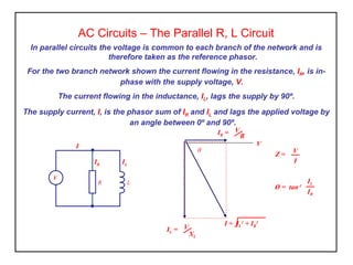
  • 1. AC Circuits – The Parallel R, L Circuit In parallel circuits the voltage is common to each branch of the network and is therefore taken as the reference phasor. For the two branch network shown the current flowing in the resistance, IR, is in- phase with the supply voltage, V. The current flowing in the inductance, IL, lags the supply by 90º. The supply current, I, is the phasor sum of IR and IL and lags the applied voltage by an angle between 0º and 90º. Ø = tan-1 IL IR I = IL 2 + IR 2 IR = V R V θ IL = V XL Z = V I R L IL I IR V
  • 2. AC Circuits – The Parallel R, C Circuit Ø = tan-1 IC IR I = IC 2 + IR 2 IR = V R V θ IC = V XC For the two branch network shown the current flowing in the resistance, IR, is in- phase with the supply voltage, V. The current flowing in the capacitance, IC, leads the supply by 90º. The supply current, I, is the phasor sum of IR and IC and leads the applied voltage by an angle between 0º and 90º. Z = V I R I IR V C IC
  • 3. AC Circuits – Parallel Networks Activity 1. A 20Ω resistor is connected in parallel with a 2.387mH inductance across a 60V, 1kHz supply. Calculate a) the current in each branch, b) the supply current, c) the circuit phase angle, d) the circuit impedance and d) the power taken from the supply. 2. A 30µF capacitor is connected in parallel with an 80Ω resistor across a 240V, 50Hz supply. Calculate a) the current in each branch, b) the supply current, c) the circuit phase angle, d) the circuit impedance and d) the true power and the power taken from the supply (apparent power). 3. Sketch the phasor diagram for each of the above.
  • 4. AC Circuits – The Parallel R, L and C Network For the three branch network shown the current flowing in the resistance, IR, is in- phase with the supply voltage, V. The current flowing in the inductance, IL, lags the supply by 90º. The current flowing in the capacitor, IC, leads the supply by 90º The supply current, I, is the phasor sum of IR and IL and lags the applied voltage by an angle between 0º and 90º. R L IL I IR V C IC Ø = tan-1 ( IC – IL ) IR Z = V I I = IR 2 + ( IC 2 – IL 2 ) IR = V R V θ IL = V XL IC = V XC IC - IL
  • 5. AC Circuits – Parallel Networks Activity 1. A 50Ω resistor is connected in parallel with a 150mH inductance and a 100µF capacitance across a 100V, 50Hz supply. Calculate a) the current in each branch, b) the supply current, c) the circuit phase angle, d) the circuit impedance and d) the power taken from the supply. 2. A 35µF capacitor is connected in parallel with a 200mH inductor and a 20Ω resistor across a 240V, 60Hz supply. Calculate a) the current in each branch, b) the supply current, c) the circuit phase angle, d) the circuit impedance and d) the true power and the power taken from the supply (apparent power). 3. Sketch the phasor diagram for each of the above.
  • 6. AC Circuits – The True Parallel Circuit The true parallel circuit represents a more common practical system with the coil resistance as a series element to the inductive branch and a parallel connected capacitance. Current IC leads the applied voltage by 90º and is shown in phasor IC. The current IL through the inductance lags the applied voltage by an angle dependant on the value of its resistance, R. R L IL I V C IC V IC = V/XC V is the reference for the parallel capacitance branch IL VR = ILR VL = ILXL V Ø IL is the reference for the series R/ L branch Since V is a common phasor to both diagrams we can combine them to provide a diagram for the complete circuit V IC IL VR I Ø The supply current is now the phasor sum of IC and IL with the phase angle Ø to the applied voltage.
  • 7. IL is the reference for the series R/ L branch AC Circuits – The True Parallel Circuit In this arrangement there are two series circuits connected in parallel. We can analyse this through two separate phasor diagrams each with the current as the reference phasor. Then superimpose them making the supply voltage the reference phasor. R1 L IL I V C IC Since V is a common phasor to both diagrams we can combine them to provide a diagram for the complete circuit The supply current is now the phasor sum of IC and IL with the phase angle Ø to the applied voltage. R2 IL VR1 = ILR1 VL = ILXL V Ø1 IC VR2 = IC R2 VC = IC XC V Ø2 IC is the reference for the series R/ C branch I V IC Ø2 IL Ø1 Ø
  • 8. Parallel AC Circuits – Summary • Each branch is determined individually as a series circuit. • Individual phasor diagrams are superimposed. • At resonance the current is at its minimum. • Parallel resonant circuits are known as ‘rejector’ circuits. • Rejector circuits provide a high impedance at the resonant frequency. • The impedance at resonance is called the ‘dynamic’ impedance.