Weitere ähnliche Inhalte
Ähnlich wie 20130644 (20)
Kürzlich hochgeladen (20)
20130644
- 1. 44 www.aiche.org/cep June 2013 CEP
Back to Basics
C
entrifugal compressors, also called radial com-
pressors, are critical equipment in a wide variety
of applications in the chemical process industries
(CPI). As their name suggests, their primary purpose is to
compress a fluid (a gas or gas/liquid mixture) into a smaller
volume while simultaneously increasing the pressure and
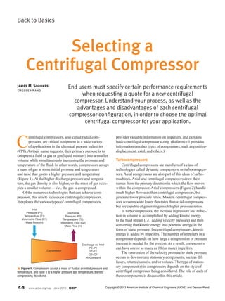
temperature of the fluid. In other words, compressors accept
a mass of gas at some initial pressure and temperature
and raise that gas to a higher pressure and temperature
(Figure 1). At the higher discharge pressure and tempera-
ture, the gas density is also higher, so the mass of gas occu-
pies a smaller volume — i.e., the gas is compressed.
Of the numerous technologies that can achieve com-
pression, this article focuses on centrifugal compressors.
It explores the various types of centrifugal compressors,
provides valuable information on impellers, and explains
basic centrifugal compressor sizing. (Reference 1 provides
information on other types of compressors, such as positive-
displacement, axial, and others.)
Turbocompressors
Centrifugal compressors are members of a class of
technologies called dynamic compressors, or turbocompres-
sors. Axial compressors are also part of this class of turbo
machines. Axial and centrifugal compressors draw their
names from the primary direction in which the flow moves
within the compressor. Axial compressors (Figure 2) handle
much higher flowrates than centrifugal compressors, but
generate lower pressure ratios. Modern centrifugal compres-
sors accommodate lower flowrates than axial compressors
but are capable of generating much higher pressure ratios.
In turbocompressors, the increase in pressure and reduc-
tion in volume is accomplished by adding kinetic energy
to the fluid stream (i.e., adding velocity pressure) and then
converting that kinetic energy into potential energy in the
form of static pressure. In centrifugal compressors, kinetic
energy is added by impellers. The number of impellers in a
compressor depends on how large a compression or pressure
increase is needed for the process. As a result, compressors
can have one or as many as 10 (or more) impellers.
The conversion of the velocity pressure to static pressure
occurs in downstream stationary components, such as dif-
fusers, return channels, and/or volutes. The type of station-
ary component(s) in compressors depends on the style of
centrifugal compressor being considered. The role of each of
these components is discussed in this article.
End users must specify certain performance requirements
when requesting a quote for a new centrifugal
compressor. Understand your process, as well as the
advantages and disadvantages of each centrifugal
compressor configuration, in order to choose the optimal
centrifugal compressor for your application.
James M. Sorokes
Dresser-Rand
Selecting a
Centrifugal Compressor
Inlet
Pressure (P1)
Temperature (T1)
Volumetric Flow (Q1)
Mass Flow (m)
Discharge
Pressure (P2)
Temperature (T2)
Volumetric Flow (Q2)
Mass Flow (m)
Discharge vs. Inlet
P2>P1
T2>T1
Q2<Q1
m=Constant
Compressor
p Figure 1. Compressors accept a mass of fluid at an initial pressure and
temperature, and raise it to a higher pressure and temperature, thereby
compressing its volume.
Copyright © 2013 American Institute of Chemical Engineers (AIChE) and Dresser-Rand
- 2. CEP June 2013 www.aiche.org/cep 45
A simple analogy
To help understand
the concepts of velocity
and dynamic pressure,
think about a fan that
you might have in your
home or office. If you
place your hand in front
of the fan, you can feel the kinetic energy that the fan blades
have added to the air. If you place your hand behind the
fan, you can feel movement of the air as it is being drawn
into the fan. The suction is caused by a reduction in static
pressure due to the acceleration of the air by the fan blades,
thereby drawing more air into the fan.
Now imagine that you arrange several fans in a row
inside an enclosure to ensure that all of the flow goes in one
direction. Imagine how much force you would feel coming
out of the last fan in the stack after each fan accelerates the
air (i.e., adds more kinetic energy). That is the basic concept
behind a compressor — a series of rotating blades adding
energy to the gas.
Now suppose that the flow changes direction as it passes
through the rotating blades so that it exits the blades travel-
ing radially outward rather than in an axial direction (Fig-
ure 3). That is the fundamental difference between the axial
compressor’s rotor and the centrifugal (or radial) compres-
sor’s impeller — the axial rotor discharges flow in the axial
direction while the centrifugal impeller discharges in a
radial direction.
The impeller adds kinetic energy to the fluid in the same
way the blades of a household fan do, although the cen-
trifugal impeller adds more energy to the fluid than can be
added with a typical fan blade. Thus, it is possible to achieve
much higher pressures with centrifugal impellers. Multistage
centrifugal compressors have multiple impellers stacked
together and connected by flow passages.
Although centrifugal compressors are sometimes called
radial compressors, most of the flow exiting a centrifugal
impeller does not travel in a radial direction. Rather, the flow
travels to a large extent in a tangential direction.
This motion is characteristic of a rotating disk. Consider
the direction that wood dust travels when you are using a disk
sander, or that sparks fly when you are using a grinding wheel
(Figure 4). Similarly, the fluid that passes through a centrifu-
gal impeller is flung out along a path that has both a radial
velocity component and a tangential velocity component.
Impellers — the heart of the centrifugal compressor
The most critical components in any centrifugal com-
pressor, regardless of style, are the impellers. If the impel-
lers do not provide a high efficiency and good overall flow
range, it is impossible for the compressor to achieve a
Intake
Inlet
Guide Vane
Stator Vane
Spring Link
Drive Ring
Stator Casing
Tie Bolt
Discharge
Guide Vane
Assembly
Plain Bearing
Body and Cap
Stub Shaft
Discharge Volute Assembly
Discharge Seal
Labyrinth
Package
Ring
Rotor Blade
Rotor
Disc
Tie Bolt
Labyrinth
Package
Ring
Dischargeu Figure 2. In an axial
compressor, flow moves in
an axial direction (from left to
right in this diagram), rather
than in a circular direction as
in centrifugal compressors.
Axial Centrifugal
p Figure 3. Flow exits an axial rotor (left) in an axial direction, while flow
from a centrifugal impeller (right) exits radially.
Radial
Component
Tangential
Component
Exit Flow
Inlet
Exit Flow
p Figure 4. Flow exits a centrifugal impeller in the direction of rotation,
just as sparks fly from a grinding wheel. The red arrows indicate the
direction of rotation.
Copyright © 2013 American Institute of Chemical Engineers (AIChE) and Dresser-Rand
- 3. 46 www.aiche.org/cep June 2013 CEP
Back to Basics
high efficiency and good flow range.
Impellers are the only rotating aerodynamic components
in a centrifugal compressor. They provide 100% of the
kinetic energy that is added to the gas and can be responsible
for up to 70% of the static pressure rise in a stage.
They are also the most efficient component in a stage.
Well-designed impellers can achieve efficiencies in excess
of 96%, that is, only 4% of the energy expended is lost. The
losses in the stationary hardware reduce the overall stage
efficiency from the baseline established by the impeller.
Therefore, if the performance of the impellers is poor, the
overall compressor performance can only be worse.
Centrifugal compressor impellers can be categorized
as shrouded or unshrouded (Figure 5), and their blades as
two-dimensional or three-dimensional (Figure 6). The type
of impeller chosen for a particular application depends on
many considerations, such as required operating speed,
desired pressure ratio, desired efficiency, and equipment
cost.
The absence of a cover allows unshrouded impellers to
operate at higher rotational, or tip, speeds. The pressure ratio
generated by an impeller is proportional to the square of the
operating speed. Therefore, open (unshrouded) impellers
are capable of generating much higher pressure ratios than
shrouded impellers. Most shrouded impellers generate pres-
sure ratios of 3:1 or less, whereas unshrouded impellers can
reach pressure ratios of 10:1 or higher.
However, unshrouded impellers tend to be less efficient
because of the high losses associated with the tip leakage
flow (i.e., the flow that leaks over the rotating blades). Tip
leakage does not occur in a covered impeller.
The selection of blade style depends on many factors;
from an aerodynamic perspective, the most important is the
impeller flow coefficient. The flow coefficient, ϕ, relates an
impeller’s volumetric flow capacity, Q, operating speed, N,
and exit diameter, D2:
Q
N D
1
2
3 ( )=
×
Low-flow-coefficient impellers are characterized by
long, narrow passages, while high-flow-coefficient impel-
lers have much wider passages to accommodate the higher
flowrates.
The compressor rotor shown in Figure 7 contains impel-
lers with a wide range of flow coefficients. The impeller with
the highest flow coefficient is located at the right end of the
rotor. The remaining impellers are progressively narrower,
with increasing fluid pressure and decreasing volumetric
flowrate. The impeller with the lowest flow coefficient (at
the left, closest to the center of the machine) is much nar-
p Figure 5. Impellers can be either shrouded (top) or open (bottom).
p Figure 6. Impeller blades can be either two-dimensional (top) or three-
dimensional (bottom). The 2D blades in the top image have a circular arc
shape, whereas the blades in the lower image have a complex 3D shape.
Copyright © 2013 American Institute of Chemical Engineers (AIChE) and Dresser-Rand
- 4. CEP June 2013 www.aiche.org/cep 47
rower than the high-flow-coefficient impeller on the right.
Low-flow-coefficient impellers typically have simpler
blades, such as the 2D blades on the top of Figure 6, which
are defined by circular arc sections. Higher-flow-coefficient
impellers typically have complex, 3D blades (Figure 6,
bottom) that cannot be defined by any simple geometric
shape. More complex blade shapes are defined with sophis-
ticated computer programs that determine the blade contours
necessary to ensure optimal aerodynamics.
Due to their narrow passages and simpler blades, low-
flow-coefficient impellers deliver lower efficiency than
high-flow-coefficient impellers. However, applications may
require the use of impellers with a low flow
coefficient when the process flowrate is small
relative to the operating speed or impel-
ler diameter (see Eq. 1), or when upstream
stages or compressors reduce the flowrate,
and require low-flow-coefficient stages to
complete the compression process.
Centrifugal compressor configurations
Flow exits an impeller in both a radial
direction and a tangential direction, and is
often described as swirling outward. The
control, or guidance, of this swirling flow is
one of the primary purposes of a centrifugal
compressor’s stationary components. The
other purpose is to efficiently convert the
dynamic pressure exiting the impeller into
static pressure. The specific stationary com-
ponents depend on the style of centrifugal
compressor in use.
Multistage centrifugal compressors gener-
ally fall into two categories: between-bearing
designs, and integrally geared designs.
Between-bearing configurations
In the between-bearing design, the
impellers are mounted on a single shaft.
Figure 8 shows a cross-section of a three-
stage between-bearing compressor. A driver
(e.g., an electric motor, steam turbine, or
gas turbine) rotates the shaft and all of the
impellers at the same speed. Flow enters
the compressor via the inlet and flows into
the inlet guide, which distributes the flow
circumferentially around the machine to
provide a uniform velocity and pressure at
the entrance of the first-stage impeller.
As described earlier, the rotating impel-
ler adds kinetic energy or velocity pressure
to the gas and the flow exits the impeller
with tangential velocity (or exit swirl). The flow then swirls
outward though the diffuser along a spiral path (Figure 9).
As the flow moves outward in the diffuser, it encounters
a larger area (due to the increasing radius) and the flow
velocity decreases. This decrease in velocity results in an
increase in static pressure (i.e., the velocity pressure is
converted to static pressure). At the exit of the diffuser, the
flow passes through the return bend, which redirects the flow
from spiraling radially outward to spiraling radially inward.
Next, the flow passes through the return channel, which has
vanes that capture the swirling flow and reorient it radially
inward toward the center of the compressor. This process
Low-Flow-Coefficient Impeller
Medium-Flow-
Coefficient Impeller
High-Flow-Coefficient
Impeller
p Figure 7. This compressor rotor has impellers with a wide range of flow coefficients, from low
at the left to high at the right.
Inlet
Diffuser
Return Bend
Return
Channel
Outlet
Volute
Seal
Bearing
Seal
Bearing
Shaft Inlet
Guide
Impellers Balance
Piston
p Figure 8. A cross-sectional view of a three-stage centrifugal compressor with a between-
bearing design.
Copyright © 2013 American Institute of Chemical Engineers (AIChE) and Dresser-Rand
- 5. 48 www.aiche.org/cep June 2013 CEP
Back to Basics
removes any remaining tangential velocity, preparing the
flow for the next stage of compression. The flow then enters
the next inlet guide and impeller. This cycle is repeated in
every impeller stage until the desired discharge pressure and
reduction in volumetric flow is achieved. Finally, the gas
stream exiting the final diffuser is captured by a volute (or
collector), which captures the flow around the circumference
of the compressor and guides it into the discharge piping.
Arrangements. Between-bearing compressors come
in a wide variety of configurations that fall into two catego-
ries: straight-through and back-to-back.
In the straight-through arrangement, the flow enters
one end of the compressor and exits the opposite end.
The compressor shown in Figure 8 has a straight-through
arrangement.
In the back-to-back arrangement, the impellers face in
opposite directions, as shown in Figure 7. In this design,
the main inlet is at the right end of the rotor and the impel-
lers guide the flow toward the center of the machine. After
passing through four impellers (four stages of compression),
the flow is piped to the secondary inlet at the left end of
the compressor. The remaining five impellers complete the
compression process and the flow exits at the center of the
compressor. This configuration reduces the pressure on the
shaft end seals.
Both the straight-through and back-to-back arrange-
ments can be configured to allow intercooling throughout the
compression process. Intercooling is often necessary to keep
the temperatures of the compressor material at acceptable
levels to maintain their strength. Intercooling also reduces
the power required to complete the necessary compression.
Compressors with a high discharge pressure tend to use
a back-to-back arrangement. Each original equipment manu-
facturer (OEM) has different design rules that dictate when
to use the back-to-back arrangement, however, it is com-
monplace for compressors with discharge pressures above
2,000 psi.
Casings. Between-bearing compressors are available
with one of two basic case types: horizontally/axially split or
radially split. In the horizontally/axially split compressor, the
casing is comprised of two halves with the horizontal joint
bolted together (Figure 10). These cases
are typically limited to lower-pressure
applications (i.e., discharge pressures
less than 1,200 psia).
Radially split compressors are typi-
cally referred to as barrel compressors
(Figure 11). The increased strength pro-
vided by the cylinder of the barrel casing
allows barrel compressors to operate at
much higher pressures than horizontally
split compressors. In fact, barrel com-
pressors that exceed 12,000-psia
discharge pressure are available. For
these extremely high-pressure applica-
tions, elaborate sealing systems are
needed to prevent leakages.
The high rotational speed and length
of centrifugal compressor rotors make
robust support or bearing systems that
limit vibrations to acceptable levels
necessary. Therefore, between-bearing
Impeller ExitFlow Follows
Logarithmic Spiral Path
Diffuser Exit
Impeller Rotation
p Figure 9. In this computational fluid dynamics (CFD) depiction, as the
flow swirls outward from the impeller, the flow velocity decreases.
Top Half of Case
Bolts
Horizontal Split (Red Line)
Bottom Half of Case
Discharge Nozzle
Inlet Nozzle (Obscured by Pedestal)
p Figure 10. A horizontally/axially split compressor is held together with bolts. The horizontal joint is
highlighted in red.
Copyright © 2013 American Institute of Chemical Engineers (AIChE) and Dresser-Rand
- 6. CEP June 2013 www.aiche.org/cep 49
configurations typically require two radial bearings and one
thrust bearing to support the shaft and to compensate for
changes in axial thrust as the compressor operates at dif-
ferent flow conditions. (References 1 and 2 provide further
details on these and other commonly used bearings.)
Another critical component, especially in high-pressure
compressors in hydrocarbon or toxic gas applications, is
the shaft end seal, which keeps the process gases from leak-
ing to the atmosphere. Gas seals have gained wide accep-
tance in the turbomachinery community and are the seal
of choice for most applications. Significant advances have
been made in recent years on these seals. (References 1
and 3 provide more information on the design and advance-
ment of gas seals.)
Integrally geared configurations
In an integrally geared compressor, the impellers are
mounted at the ends of multiple pinions that can rotate at
different speeds depending on the gear ratio between the
individual pinions and the bull gear(s). The number of
impellers and number of pinions vary depending on the
application. Typical integrally geared compressors have two
to eight (or more) pinions with two impellers mounted at the
opposite ends of each pinion. This configuration is simpler
aerodynamically, but more complicated rotordynamically
and mechanically, than the between-bearing configuration.
Flow enters the first stage of an integrally geared
compressor (Figure 12) via an axial inlet or straight run of
pipe. Depending on the design, the flow might pass through
an inlet guide before entering the
impeller. The impeller adds kinetic
energy to the gas stream. Flow exiting
the impeller enters a diffuser, which
converts a portion of the velocity
pressure to static pressure. At this
point, the flow enters a discharge
volute (collector). The flow from the
volute is then piped to the axial inlet
of the next stage, which eliminates
the need for the return bend and the
return channel used in the between-
bearing design.
Integrally geared compres-
sors have several advantages over
between-bearing configurations. The
Case is a
Cylinder
Bundle Slides Into Casing
p Figure 11. In a radially split compressor, the case is a cylinder and a compressor bundle slides into the
casing.
First-Stage Inlet
Bull Gears
Third-Stage Inlet
Pinion Final Discharge
Second-Stage
Inlet
Fourth-Stage
Inlet
Volute
Diffuser
Impeller
Seal
Pinion
Inlet Guide
VanesAxial
Inlet
p Figure 12. An integrally geared compressor has multiple pinions driven by bull gears. An impeller is mounted on each end of each pinion.
Copyright © 2013 American Institute of Chemical Engineers (AIChE) and Dresser-Rand
- 7. 50 www.aiche.org/cep June 2013 CEP
Back to Basics
flow in the inlet section of the between-bearing design must
be distributed around the circumference of the compressor,
which requires extra turning and creates pressure losses. The
axial inlet of an integrally geared compressor, on the other
hand, requires a straight run of pipe and therefore has lower
aerodynamic losses than the inlet of the between-bearing
design. Additionally, because the impellers can be mounted
to different pinions in an integrally geared compressor, it
is possible to further tune the performance of a stage by
varying the impeller’s speed or choosing an impeller with a
different diameter altogether. The elimination of the return
bend and return channel in an integrally geared compressor
reduces the losses in each stage, although the volute or col-
lector losses are only slightly lower.
However, the aspects of the integrally geared design
that give it an aerodynamic advantage are also the root of its
rotordynamic and mechanical disadvantages. The integrally
geared compressor contains a large number of bearings and
seals — a minimum of two bearings and two seals for each
pinion and additional bearings for the bull gears. Vibration
related to gear meshing in integrally geared units is some-
times a problem. Because the impellers are located outside
the bearing supports, they can wobble and vibrate if not
mounted or balanced properly.
Between-bearing and integrally geared compressors both
have advantages and disadvantages, and the choice between
the two styles often depends on the particular application.
Specifying compressor performance requirements
An article scheduled for the July 2013 issue of CEP will
address compressor performance testing and will include a
detailed discussion of compressor performance parameters.
This article focuses only on those parameters that end users
must specify to an OEM when requesting a quote for a new
compressor.
At a minimum, the user must specify the flow range that
the compressor must handle. This can be specified as a range
of mass flowrates (typically lb/min or kg/min) or volumetric
flowrates (ft3/min or m3/min). Next, the user must specify
the composition of the gas to be compressed as well as the
range of pressures and temperatures of the gas as it enters
the compressor for each operating condition. The OEM
will use a real-gas equation (as agreed upon with the user)
to determine the gas properties for the mixture. Finally, the
user must specify the pressure ratio that the compressor must
achieve. Alternatively, the user might specify the discharge
pressure that must be achieved and then work with the OEM
to determine an acceptable range of inlet pressures.
In many situations, the end user will also specify a
driver. This driver needs to be able to deliver a certain
amount of horsepower and operate over a specific speed
range. Therefore, the OEM must size the compressor to
operate within the driver’s speed range while not exceeding
the horsepower capability of the driver. Alternatively, the
user might ask the OEM to select the driver as well as the
compressor and then make the purchasing decision based on
the overall compression system cost.
End users often must choose among compressors with
impellers that have a range of head coefficients and pressure
ratios. Head (Headp) is the measure of the amount of energy
required to elevate a fixed amount of gas from one pressure
level to a higher pressure level:
Head
P
P
2p 1
2
1
( )=
where k is the ratio of specific heats (CP/CV); CP is the
specific heat at constant pressure; CV is the specific heat at
constant volume; z is the compressibility of the gas; R is the
gas constant (1,545/mole-weight) in (ft-lbf)/(lb-mol)(°R); T1
is the inlet temperature in °R; P1 is the inlet pressure in psia;
and P2 is the discharge pressure in psia.
The head coefficient, µp, relates the head increase to the
operating speed, N, and impeller exit diameter, D2. The head
coefficient can be determined by:
Head
3p
2
2 ( )µ =
where gc is the gravitational constant; U2 is the peripheral
velocity of the impeller trailing edge (NπD2/720) in ft/s; D2
is the impeller blade exit diameter in in.; and N is the rota-
tional speed in rotations per min.
In general, impellers that generate a high head or high
pressure ratio have a narrower flow range than impellers that
generate a lower head or lower pressure ratio. High-head-
coefficient impellers also provide lower rise-to-surge than
lower-head-coefficient designs. Rise-to-surge is a measure of
how much the pressure increases between the design flow-
rate and the flowrate at which surge will occur. Compressor
surge is a complete breakdown in compression that occurs
when a compressor is run either at a much lower flowrate
than intended or at a much higher discharge pressure than
intended. End users often specify a minimum rise-to-surge
value when purchasing compressors.
Figure 13 is a simplified compressor performance map
showing the head coefficient curves for high- and low-head-
coefficient impellers. The black arrows immediately below
each line indicate the relative values of rise-to-surge of the
two impeller styles. The low-head-coefficient impeller has
a steeper rise-to-surge slope than the high-head-coefficient
impeller. Therefore, for a given change in flowrate, there will
be a greater change in operating pressure for the low-head-
coefficient design than for the high-head-coefficient design.
Copyright © 2013 American Institute of Chemical Engineers (AIChE) and Dresser-Rand
- 8. CEP June 2013 www.aiche.org/cep 51
Surge is a violent phenomenon, and it can cause exten-
sive damage to compressor components. Therefore, sophis-
ticated control systems are put in place to keep the compres-
sor from operating in surge. Many surge control systems
monitor the compressor’s discharge pressure to determine
where the compressor is operating. Because the low-head-
coefficient impeller has a steeper risetosurge slope, the
system can more precisely determine where the compres-
sor is operating and do a more effective job of keeping the
compressor out of surge.
Knowing the mass flowrate, the head that the compres-
sor must generate, and the compressor efficiency, you can
determine the horsepower needed to drive a compressor. The
efficiency, η, relates the actual work done on the gas (i.e.,
compressing the gas) to the total work input into the com-
pression system (i.e., from the driver, overcoming bearing
losses, etc.):
n
ln
η = =
−
where k is the ratio of specific heats; Pr is the pressure ratio;
and Tr is the temperature ratio. The right side of Eq. 4 is
the formula for polytropic efficiency, the definition most
frequently used by compressor OEMs.
The horsepower requirement is related to the mass flow-
rate, head, and efficiency as follows:
≈
×
Because horsepower is inversely proportional to
efficiency, the compressor with the highest efficiency will
require the least horsepower. Horsepower is directly pro-
portional to both mass flowrate and head, so the higher the
flowrate and/or head, the higher the horsepower requirement
of the driver will be.
When selecting a centrifugal compressor, the OEM’s
application engineers will meet with the end user’s process
engineers to review the process requirements, develop
various compressor arrangements, and then agree on the
most effective configuration for the given application. The
OEM will provide the end user with a formal proposal that
includes the expected performance maps for the compressor
or compressors needed to satisfy the requirements. u
p Figure 13. Compressors with a high head coefficient have a smaller
rise-to-surge than compressors with low head coefficients. The black
arrows under the curves indicate the level of rise.
Literature Cited
1. Bloch, H., “A Practical Guide to Compressor Technology,”
McGraw Hill, New York, NY (1996).
2. Vance, J. M., “Rotordynamics of Turbomachinery,” Wiley Inter-
science, New York, NY (1988).
3. Stahley, J., “Dry Gas Seals Handbook,” PennWell Publishing,
Tulsa, OK (2005).
JAmeS m. (JIm) SorokeS is a principal engineer at Dresser-Rand with more
than 36 years of experience in the turbomachinery industry. He joined
Dresser-Clark (now Dresser-Rand) after graduating from St. Bonaven-
ture Univ. in 1976 with a BS in Physics. As a member and later supervi-
sor in the Aerodynamics Group, his primary responsibilities included
the development, design, and analysis of all aerodynamic components
of centrifugal compressors. He also served as Manager of Aero/Thermo
Design Engineering, and in 2004 was named Manager of Development
Engineering, where he became involved in all aspects of new product
development and product upgrades. In his current position, he is
responsible for various projects related to compressor development
and testing, and is heavily involved in mentoring and training in the
field of aerodynamic design, analysis, and testing. He is a member of
the American Institute of Aeronautics and Astronautics (AIAA), a Fellow
of ASME, and a member of the ASME Turbomachinery Committee. He
has authored or co-authored more than 40 technical papers and has
instructed seminars and tutorials at Texas A&M Univ. and Dresser-Rand.
He currently holds three U.S. patents and has five others pending.
Additional Reading
Aungier, R. H., “Centrifugal Compressors: A Strategy for Aero-
dynamic Design and Analysis,” ASME Press, New York, NY
(2000).
Japikse, D., “Centrifugal Compressor Design and Performance,”
Concepts ETI, Wilder, VT (1996).
Shepherd, D. G., “Principles of Turbomachinery,” MacMillan
Publishing, New York, NY (1956).
Sorokes, J. M., “Industrial Centrifugal Compressors — Design
Considerations,” ASME Paper No. 95WA/PID2, ASME Winter
Annual Meeting, San Francisco, CA (1995).
Sorokes, J. M., and M. J. Kuzdzal, “Centrifugal Compressor
Evolution,” Turbomachinery Symposium Proceedings, Texas
A&M Univ., Houston, TX (2010).
Sorokes, J. M., “Range v. Efficiency — Striking the Proper Balance,”
Turbomachinery Symposium Proceedings, Texas A&M Univ.,
Houston, TX (2011).
Flow Coefficient
HeadCoefficient
High Head Coefficient
Low Head Coefficient
Surge Line
Copyright © 2013 American Institute of Chemical Engineers (AIChE) and Dresser-Rand