Centrifugal and gear pump theory dms
•
0 gefällt mir•370 views

Centrifugal pumps work by converting mechanical energy into hydraulic energy using centrifugal force. They are commonly used to lift liquids to higher elevations. The document discusses key components of centrifugal pumps including the impeller, casing, suction and delivery pipes. It also covers critical concepts such as net positive suction head (NPSH), wearing rings, stuffing boxes, and lantern rings which are used to seal the pump shaft. Cavitation and its damaging effects are also summarized.

Empfohlen
Weitere ähnliche Inhalte
Was ist angesagt?
Was ist angesagt? (20)
Ähnlich wie Centrifugal and gear pump theory dms
Ähnlich wie Centrifugal and gear pump theory dms (20)
Mehr von Sagar Dhotare
Mehr von Sagar Dhotare (20)
Kürzlich hochgeladen
Kürzlich hochgeladen (20)
Centrifugal and gear pump theory dms
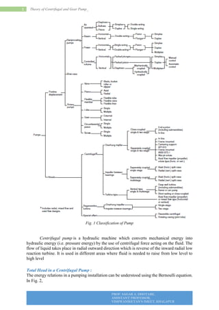
- 1. THEORY OF CENTRIFUGAL AND GEAR PUMP_ PROF. SAGAR A. DHOTARE, ASSISTANT PROFESSOR, VISHWANIKETAN’S IMEET, KHALAPUR 1 Theory of Centrifugal and Gear Pump_ Fig. 1 Classification of Pump Centrifugal pump is a hydraulic machine which converts mechanical energy into hydraulic energy (i.e. pressure energy) by the use of centrifugal force acting on the fluid. The flow of liquid takes place in radial outward direction which is reverse of the inward radial low reaction turbine. It is used in different areas where fluid is needed to raise from low level to high level Total Head in a Centrifugal Pump : The energy relations in a pumping installation can be understood using the Bernoulli equation. In Fig. 2,
- 2. THEORY OF CENTRIFUGAL AND GEAR PUMP_ PROF. SAGAR A. DHOTARE, ASSISTANT PROFESSOR, VISHWANIKETAN’S IMEET, KHALAPUR 2 Theory of Centrifugal and Gear Pump_ Fig. 2 Pump Heads in Pump installation Considering (1) and (2) , the energy relationship in terms of head can be written as – Where, V1 and V2 are velocities, P1 and P2 are pressures, and Z1 and Z2 are elevations from a datum at points 1 and 2 respectively. Hm is the energy imparted to the liquid in moving it from point 1 to 2 and Hf is the friction loss in the piping system. The terms in the above equation are to be considered depending on the physical situation. Considering Fig. 2 the velocities and pressures at points 1 and 2 can be taken as zero and as such Hm is given by – Where, hfs and hfd are the total friction losses in the suction side and the delivery side respectively. When the delivery side is discharging to the atmosphere, the delivery head 𝑉𝑑 2 2𝑔 may be added to Hm and the pumping head becomes as – Velocity head 𝑉𝑑 2 2𝑔 is calculated using the relationship V = Q/A where Q is the discharge and A is the cross-sectional area of the pipe. The head due to frictional losses is calculated by knowing the pipe lengths on the suction and delivery sides and the pipe fittings and estimating the frictional losses through them. Standard tables giving the frictional losses through different pipe fitting are used for the purpose. Considering points S and d in Fig. 2, the energy imparted by the impeller can be written as
- 3. THEORY OF CENTRIFUGAL AND GEAR PUMP_ PROF. SAGAR A. DHOTARE, ASSISTANT PROFESSOR, VISHWANIKETAN’S IMEET, KHALAPUR 3 Theory of Centrifugal and Gear Pump_ The above equation is used in testing of the centrifugal pumps. Knowing the rate of flow and the diameter of the pipe lines in the suction and delivery sides, Vs and Vd values can be calculated. The pressure or the suction side is negative and is measured using a vacuum gauge and the pressure on the delivery side is positive and is measured using a pressure gauge. However, allowance has to be given for the location of the gauges. Net Positive Suction Head: In case of centrifugal pumps, installed above the water level, certain amount of energy is required to move the water into the eye of the impeller. The source of energy available for this purpose is the atmospheric pressure. The maximum suction lift of centrifugal pumps is dependent upon the atmospheric pressure. Atmospheric pressure varies with elevation and at sea level, its value is 1.03 kg/cm2 (14.7 psi) or 10.34 m (34 ft) of water. Theoretically, pump should be able to operate with this suction lift at sea level. But because of air leaks past the impeller and through other openings the effective suction lift is of the order of 6.34 m (18 ft) at sea level and about 4.5 m (15 ft) for most inland conditions. For obtaining higher pump efficiencies, the suction lift should be as small as possible. Fig. 3 Computation of Net Positive Suction Head Values of the atmospheric pressure at various altitudes, the vapour pressure and specific gravity of water as a function of temperature can be obtained from standard tables. The atmospheric pressure and vapour pressure are un-adjustable, but suction lift and friction head of suction side are able to adjust to be minimum for maximize the NSPHA which means energy to drive water to pump will be increased. The amount of energy required to move the water into the eye of the impeller is referred so as the net positive suction head required (NPSHR). The NPSHR is a function of the pump
- 4. THEORY OF CENTRIFUGAL AND GEAR PUMP_ PROF. SAGAR A. DHOTARE, ASSISTANT PROFESSOR, VISHWANIKETAN’S IMEET, KHALAPUR 4 Theory of Centrifugal and Gear Pump_ speed, impeller shape, liquid properties and discharge rate. Its value is determined for a particular condition using laboratory tests. If sufficient energy is not present in the liquid on the suction side of the pump to move the liquid into the eye of the impeller, then the liquid will vaporize and what is known as cavitation will occur. Cavitation could remove metal particles, cause severe vibrations and damage the functioning of the pump. The occurrence of cavitation should therefore be avoided. At a given location, for the satisfactory operation of the pump, the NPSHA should be greater than NPSHR. In order to satisfy this condition the pump may have to be lowered towards the water surface, or the suction pipe could be changed to reduce the friction loss. If NPSHA is less than NPSHR, driving energy is not sufficient to requirement air and water will be pumped together which will damage the pump. NPSH Design Considerations : Vapour pressure is strongly dependent on temperature, and thus so will both NPSHR and NPSHA. Centrifugal pumps are particularly vulnerable especially when pumping heated solution near the vapour pressure, whereas positive displacement pumps are less affected by cavitation, as they are better able to pump two-phase flow (the mixture of gas and liquid), however, the resultant flow rate of the pump will be diminished because of the gas volumetrically displacing a disproportion of liquid. Careful design is required to pump high temperature liquids with a centrifugal pump when the liquid is near its boiling point. The violent collapse of the cavitation bubble creates a shock wave that can carve material from internal pump components (usually the leading edge of the impeller) and creates noise often described as "pumping gravel". Additionally, the inevitable increase in vibration can cause other mechanical faults in the pump and associated equipment. Principle : It works on the principle of forced vortex flow. The forced vortex flow means when a certain mass of fluid or liquid is allowed to rotate by an external torque than there is a rise in pressure head of the rotating liquid takes place. This rise in pressure head is used to deliver water from one location to another. It is centrifugal force acting on the fluid that makes it to flow within the casing. The rise in the pressure head of the rotating liquid at any point is directly proportional to the square of the tangential velocity of the rotating liquid. Mathematically, How liquid is lifted to high level? At the outlet of the impeller, radius is more and because of this the rise in the pressure head is more and the liquid at the outlet discharged with a high pressure head. And because of this high pressure head, the liquid can be lifted to a very high level.
- 5. THEORY OF CENTRIFUGAL AND GEAR PUMP_ PROF. SAGAR A. DHOTARE, ASSISTANT PROFESSOR, VISHWANIKETAN’S IMEET, KHALAPUR 5 Theory of Centrifugal and Gear Pump_ Main Parts : The various main parts of a centrifugal pump are: Fig. 4 Layout of Centrifugal Pump 1. Impeller : It is the rotating part of the pump. The impeller is mounted on a shaft and the shaft of impeller is again connected with the shaft of an electric motor. It is rotated by the motor and consists of series of backward curved blades. Impellers of pumps are classified based on the number of points that the liquid can enter the impeller and also on the amount of webbing between the impeller blades. Impellers can be either single-suction or double-suction. A single-suction impeller allows liquid to enter the center of the blades from only one direction. A double-suction impeller allows liquid to enter the center of the impeller blades from both sides simultaneously. Figure 4.1 shows simplified diagrams of single and double-suction impellers. Fig. 4.1 Single-Suction and Double-Suction Impellers Impellers can be open, semi-open, or enclosed.
- 6. THEORY OF CENTRIFUGAL AND GEAR PUMP_ PROF. SAGAR A. DHOTARE, ASSISTANT PROFESSOR, VISHWANIKETAN’S IMEET, KHALAPUR 6 Theory of Centrifugal and Gear Pump_ Fig. 4.2 Open, Semi-Open, and Enclosed Impellers The open impeller consists only of blades attached to a hub. The semi-open impeller is constructed with a circular plate (the web) attached to one side of the blades. The enclosed impeller has circular plates attached to both sides of the blades. Enclosed impellers are also referred to as shrouded impellers. Figure 4.2 illustrates examples of open, semi-open, and enclosed impellers. The impeller sometimes contains balancing holes that connect the space around the hub to the Suction side of the impeller. The balancing holes have a total cross-sectional area that is considerably greater than the cross-sectional area of the annular space between the wearing ring and the hub. The result is suction pressure on both sides of the impeller hub, which maintains a hydraulic balance of axial thrust. 2. Casing : It is an air tight passage which surrounds the impeller. The design of the casing is done in such a way that it is capable of converting the kinetic energy of the water discharging from the outlet of the impeller into pressure energy before it leaves the casing and enters into the delivery pipe. Commonly three types of casing are used in centrifugal pump and these are (i) Volute Casing: It is a spiral type of casing in which the area of flow increases gradually. The increase in area of flow decreases the velocity and increases the pressure of the liquid that flows through the casing. The volute casing is shown in figure above: (ii) Vortex Casing: In vortex casing, a circular chamber is introduced in between the impeller and casing. This is done in order to prevent the loss of energy due to formation of eddies. The efficiency of the vortex casing is more than that of the volute casing. (iii) Casing with Guide Blades: In this casing, the impeller is surrounded by series of guide blades. The guide blades are mounted on a ring which is called as diffuser. The design of the guide vanes are kept as such that the water which is leaving the impeller enters the guides without shock. The area of the guide vanes increases; this helps to decrease the velocity of the liquid and increases its pressure. After guide vanes, water passes through the surrounding casing. In most of the cases, the casing remains concentric with the impeller. 3. Suction Pipe with Foot Valve and Strainer : A pipe whose one end is connected with the inlet of the impeller and the other end is dipped into the sump of water is called suction pipe. The suction pipe consists of a foot valve and strainer at its lower end. The foot valve is a one way valve that opens in the upward direction. The strainer is used to filter the unwanted particle present in the water to prevent the centrifugal pump from blockage.
- 7. THEORY OF CENTRIFUGAL AND GEAR PUMP_ PROF. SAGAR A. DHOTARE, ASSISTANT PROFESSOR, VISHWANIKETAN’S IMEET, KHALAPUR 7 Theory of Centrifugal and Gear Pump_ 4. Delivery Pipe : It is a pipe whose one end is connected to the outlet of the pump and other end is connected to the required height where water is to be delivered. Centrifugal Pump other Components: Centrifugal pumps vary in design and construction from simple pumps with relatively few parts to extremely complicated pumps with hundreds of individual parts. Some of the most common components found in centrifugal pumps are wearing rings, stuffing boxes, packing, and lantern rings. These components are shown in Figure 4.3 . Fig. 4.3 Centrifugal Pump Components a. Wearing Rings: Centrifugal pumps contain rotating impellers within stationary pump casings. To allow the impeller to rotate freely within the pump casing, a small clearance is designed to be maintained between the impeller and the pump casing. To maximize the efficiency of a centrifugal pump, it is necessary to minimize the amount of liquid leaking through this clearance from the high pressure or discharge side of the pump back to the low pressure or suction side. Some wear or erosion will occur at the point where the impeller and the pump casing nearly come into contact. This wear is due to the erosion caused by liquid leaking through this tight clearance and other causes. As wear occurs, the clearances become larger and the rate of leakage increases. Eventually, the leakage could become unacceptably large and maintenance would be required on the pump. To minimize the cost of pump maintenance, many centrifugal pumps are designed with wearing rings. Wearing rings are replaceable rings that are attached to the impeller and/or the pump casing to allow a small running clearance between the impeller and the pump casing without causing wear of the actual impeller or pump casing material. These wearing rings are designed to be replaced periodically during the life of a pump and prevent the more costly replacement of the impeller or the casing. b. Stuffing Box : In almost all centrifugal pumps, the rotating shaft that drives the impeller penetrates the pressure boundary of the pump casing. It is important that the pump is designed properly to control the amount of liquid that leaks along the shaft at the point that the shaft penetrates the pump casing. There are many different methods of sealing the shaft penetration of the pump casing. Factors considered when choosing a method include the pressure and temperature of the fluid being pumped, the size of the pump, and the chemical and physical characteristics of the fluid being pumped.
- 8. THEORY OF CENTRIFUGAL AND GEAR PUMP_ PROF. SAGAR A. DHOTARE, ASSISTANT PROFESSOR, VISHWANIKETAN’S IMEET, KHALAPUR 8 Theory of Centrifugal and Gear Pump_ One of the simplest types of shaft seal is the stuffing box. The stuffing box is a cylindrical space in the pump casing surrounding the shaft. Rings of packing material are placed in this space. Packing is material in the form of rings or strands that is placed in the stuffing box to form a seal to control the rate of leakage along the shaft. The packing rings are held in place by a gland. The gland is, in turn, held in place by studs with adjusting nuts. As the adjusting nuts are tightened, they move the gland in and compress the packing. This axial compression causes the packing to expand radially, forming a tight seal between the rotating shaft and the inside wall of the stuffing box. The high speed rotation of the shaft generates a significant amount of heat as it rubs against the packing rings. If no lubrication and cooling are provided to the packing, the temperature of the packing increases to the point where damage occurs to the packing, the pump shaft, and possibly nearby pump bearings. Stuffing boxes are normally designed to allow a small amount of controlled leakage along the shaft to provide lubrication and cooling to the packing. The leakage rate can be adjusted by tightening and loosening the packing gland. c. Lantern Ring : It is not always possible to use a standard stuffing box to seal the shaft of a centrifugal pump. The pump suction may be under a vacuum so that outward leakage is impossible or the fluid may be too hot to provide adequate cooling of the packing. These conditions require a modification to the standard stuffing box. One method of adequately cooling the packing under these conditions is to include a lantern ring. A lantern ring is a perforated hollow ring located near the center of the packing box that receives relatively cool, clean liquid from either the discharge of the pump or from an external source and distributes the liquid uniformly around the shaft to provide lubrication and cooling. The fluid entering the lantern ring can cool the shaft and packing, lubricate the packing, or seal the joint between the shaft and packing against leakage of air into the pump in the event the pump suction pressure is less than that of the atmosphere. d. Mechanical Seals: In some situations, packing material is not adequate for sealing the shaft. One common alternative method for sealing the shaft is with mechanical seals. Mechanical seals consist of two basic parts, a rotating element attached to the pump shaft and a stationary element attached to the pump casing. Each of these elements has a highly polished sealing surface. The polished faces of the rotating and stationary elements come into contact with each other to form a seal that prevents leakage along the shaft. Actual Working : As the electric motor starts rotating, it also rotates the impeller. The rotation of the impeller creates suction at the suction pipe. Due to suction created the water from the sump starts coming to the casing through the eye of the impeller. From the eye of the impeller, due to the centrifugal force acting on the water, the water starts moving radially outward and towards the outer of casing. Since the impeller is rotating at high velocity it also rotates the water around it in the casing. The area of the casing increasing gradually in the direction of rotation, so the velocity of the water keeps on decreasing and the pressure increases, at the outlet of the pump, the pressure is maximum. Now form the outlet of the pump, the water goes to its desired location through delivery pipe. What is priming and why it is necessary? It is process in which the suction pipe, casing and delivery pipe upto the delivery valve is filled completely with liquid to be raised from outside source before starting the motor. Priming is done to remove the air from the pump.
- 9. THEORY OF CENTRIFUGAL AND GEAR PUMP_ PROF. SAGAR A. DHOTARE, ASSISTANT PROFESSOR, VISHWANIKETAN’S IMEET, KHALAPUR 9 Theory of Centrifugal and Gear Pump_ If air is not removed from the pump than a small negative pressure is created at the suction pipe and it cannot suck the water from the water sump. So it is advised to fill the pump with water before starting it. OR Priming Centrifugal Pumps Most centrifugal pumps are not self-priming. In other words, the pump casing must be filled with liquid before the pump is started, or the pump will not be able to function. If the pump casing becomes filled with vapours or gases, the pump impeller becomes gas-bound and incapable of pumping. To ensure that a centrifugal pump remains primed and does not become gas-bound, most centrifugal pumps are located below the level of the source from which the pump is to take its suction. The same effect can be gained by supplying liquid to the pump suction under pressure supplied by another pump placed in the suction line. What is Cavitation and How it Occurs? Cavitation is a phenomenon of formation of vapour bubbles of a flowing liquid in a region where the pressure of the liquid becomes equal or less than the vapour pressure. When these vapour bubbles reaches into the region of higher pressure, they collapse and creates high impact pressure. These high impact pressure created by the vapour bubbles eroded the materials from metallic surface and produces cavity. Fig. 5 Basic phenomenon of Bubble formation For better explanation of the above cavitation phenomenon one must have knowledge of vaporization and vapour pressure. What is Vaporization? The change of liquid phase into gaseous phase is called vaporization. The vaporization depends upon the prevailing temperature and pressure condition. It occurs due to the continuous escaping of the liquid molecules from free surface of the liquid. What is Vapour Pressure? In order to understand vapour pressure, let’s take a closed vessel in which a liquid (say water) is present. Let the temperature of the water is 20o C and pressure is atmospheric. In this situation the vaporization of water takes place at 100o C. As the vaporization of water starts, the molecules of liquid (vapour) start escaping out from the free surface of the liquid. The vapour molecules escaping out from the liquid free surface gets collected between the free surface of the liquid and top of the vessel. These vapour molecules exerts pressure on the free surface of liquid. This pressure exerted by the vapour is called vapour pressure. Vapour pressure is also defined as the pressure at which the liquid changes into vapour
- 10. THEORY OF CENTRIFUGAL AND GEAR PUMP_ PROF. SAGAR A. DHOTARE, ASSISTANT PROFESSOR, VISHWANIKETAN’S IMEET, KHALAPUR 10 Theory of Centrifugal and Gear Pump_ Now, again take a closed vessel filled with a liquid (say water). Let the temperature of the water is 20o C and the pressure in the vessel is reduced by some external source. When the pressure is reduced, the vaporization temperature is also reduced. Let the pressure inside the vessel is reduced to such an extent that it becomes equal or less than the vapour pressure. In this situation the boiling of water takes place even though the temperature of liquid is 20o C. Thus the boiling of water takes place even at ordinary temperature; if the pressure is reduced as such it becomes equal to or less than the vapour pressure. Explanation of Cavitation : Considered a system in which a liquid (say water) is flowing. When the flowing water enters into a region where the pressure becomes equal to or less than that of the vapour pressure. Than the vaporization of water starts and vapour bubbles are formed in the water. When these vapour bubbles are carried by the flowing liquid in the region of higher pressure they explode. The explosion of vapour bubbles creates impact pressure of high intensity. Since the liquid flows over the metallic surface, the high pressure produced by explosion of vapour bubbles erodes the material from the metallic surface and creates cavity. This phenomenon is called cavitation. The bursting of the vapour bubbles creates noise and vibration. Cause of Cavitation : Cavitation occurs when pressure of flowing liquid in any region becomes equal to or less than the vapour pressure. Effect of Cavitation : It results in damage to the metallic surfaces and creates cavity. Creates noise and vibration due to sudden collapsing of vapour bubbles. It reduces the efficiency of hydraulic machines like turbine and pumps. Precaution for Cavitation : The pressure of the liquid in any part of the hydraulic system should not be reduced below its vapour pressure. The special materials or coating such as stainless steel and aluminium bronze, which are cavitation resistance should be used. Application : The centrifugal pump is used in almost every field to raise the liquid from low level to high level. They are mostly used at home for filling water tanks, almost in every industry such as chemical, automobile, marine, manufacturing, for irrigation etc. Power Requirements of Pumping: Power is rate of doing work. If a force or a load moves over a distance, energy is consumed and work is done, therefore- Work = Force X Distance and Rate of Work or power = work / time The scientific unit of power is the watt (W) and because this is small it is often expressed as kilowatt (1,000 W). The unit of work or energy corresponding to the Watt is the joule (J), which is defined as the work done when a force of one Newton (1 N) moves through a distance of 1 m. (Watts = joules/sec)
- 11. THEORY OF CENTRIFUGAL AND GEAR PUMP_ PROF. SAGAR A. DHOTARE, ASSISTANT PROFESSOR, VISHWANIKETAN’S IMEET, KHALAPUR 11 Theory of Centrifugal and Gear Pump_ Another unit of power used in case of pumping installations is the horsepower (HP). This is defined as the work done at the rate of 75 m kilograms per sec. in the metric units or 550 ft.lb. per second in the British units. The Horsepower is not the same in both units but has the following relationship – The pump efficiency is calculated from the above formula knowing the other two terms. Brake horsepower (BHP) refers to the power supplied by the engine or electric motor as its output. When there is direct drive from the engine or electric motor to the pump and the drive efficiency being 100 per cent, brake horsepower is equal to shaft horsepower. Selection of Centrifugal Pumps: As every pumping installation has different operating head and discharge it is necessary to select the pump such that it operates under maximum efficiency with the given head and
- 12. THEORY OF CENTRIFUGAL AND GEAR PUMP_ PROF. SAGAR A. DHOTARE, ASSISTANT PROFESSOR, VISHWANIKETAN’S IMEET, KHALAPUR 12 Theory of Centrifugal and Gear Pump_ giving the required discharge. This is done by plotting what are known as characteristic curves, both for the well and the pump. The characteristic curves represent the behaviour of the pump or the well under various operating conditions with the help of these curves different pumps can be conveniently studied and compared. 1. Head Capacity Curve: This curve for a pump shows how much water, a given pump will deliver with a given head (Fig. 6a). The curve represents the behaviour of the pump at one particular speed, head being the variable. The length AO in Fig. 6a gives the shutoff head or the head developed when the discharge valve is closed. At pump installations where there is considerable delivery head, at the instant of starting, the pump is not operating against the total head. Since the head is low, the discharge tends to be high and the engine or motor gets overloaded. Hence at the time of starting, the discharge valve should be kept closed and gradually opened afterwards. Fig. 6 Characteristics of Centrifugal Pump 2. Overall Efficiency Curve: The relationship between the efficiency of the pump and the discharge at a particular speed is represented by the efficiency curve. Also efficiency curves are obtained for different speeds of the pump. The general patterns of the curves are shown in Fig. 6b. 3. Break-Horse Power Curve: The necessary engine or motor horse power needed for a particular pump installation is obtained from the brake horse power curve. Knowing the head and the discharge and the efficiency at that discharge, the BHP is calculated and is plotted against discharge (Fig. 6c). In case a centrifugal pump has to be selected for pumping from an open water source, the total head has to be calculated for selecting the suitable pump. In case of wells the head-capacity curve of the well is made use of in the selection of the pump. The head capacity curve for a given well is constructed from the data obtained when the well is tested. This curve indicates the amount of water which the well will yield with different drawdowns. Matching the pump and well characteristics is illustrated in Fig. 7. Let the head-
- 13. THEORY OF CENTRIFUGAL AND GEAR PUMP_ PROF. SAGAR A. DHOTARE, ASSISTANT PROFESSOR, VISHWANIKETAN’S IMEET, KHALAPUR 13 Theory of Centrifugal and Gear Pump_ capacity curves of the pump and the well intersect at point P. The efficiency can be read from the efficiency curve. The efficiency obtained should be maximum or near about it. Specific Speed of Centrifugal Pumps: The performance of a pump is determined by the ability of its impeller to impart energy to the water. The design of the impeller therefore, is a basic factor for deciding the type and structure of the pump. An index to operating characteristics of pumps is the specific speed ns, expressing the relationship between speed, discharge (Q) and head (Hm). The specific speed of a centrifugal pump (ns) may be defined as the speed in revolutions per minutes of a geometrically similar pump of such a size that under corresponding conditions it would deliver 1 litre of liquid per second against a head of 1 m. The value of specific speed is useful in comparing the performance of different pumps. Fig. 7 Matching Pump and well characteristics Let Hn, Qn, Dn and n represent the head, discharge, diameter and speed of a centrifugal pump and Hs, Qs, Ds and ns similar values of a model pump.
- 14. THEORY OF CENTRIFUGAL AND GEAR PUMP_ PROF. SAGAR A. DHOTARE, ASSISTANT PROFESSOR, VISHWANIKETAN’S IMEET, KHALAPUR 14 Theory of Centrifugal and Gear Pump_ ns, however, is not a pure (non-dimensional) number. It depends on the units chosen to express Qs and Hs. Common units are 1 m for Hs and 1 m3 /sec or 1 m3 /hr or 1 1/s for Qs. In English units Hs = 1 ft, but Qs may be 1 ft3 /sec, 1 gal/min, etc. As the value of ns increases, the pump type changes from radial flow to mixed flow type and then to the axial flow type. Fig. 8 General characteristics of the different types of pumps Fig. 8 shows the general characteristics of the different types of pumps. It can be seen from these graphs that in general for low heads and high discharges the axial flow type are more efficient compared to other types at its normal working speed. In case of single impeller centrifugal pumps the value of ns varies from 300 to 5,000.
- 15. THEORY OF CENTRIFUGAL AND GEAR PUMP_ PROF. SAGAR A. DHOTARE, ASSISTANT PROFESSOR, VISHWANIKETAN’S IMEET, KHALAPUR 15 Theory of Centrifugal and Gear Pump_ Affinity Laws: Total dynamic head (H), discharge (Q) and brake horse power (P) of a pump are related to size (W, width) and speed (N, rpm) of impeller. Changing the size and speed of the impeller modifies the operational characteristics of a pump. This allows pump manufacturers or users to alter the performance of a single pump to match the system needs or understand the pump performance under different operating conditions. These relationships are known as affinity laws are given by the following wherein the subscript zero refers to the original condition. Eq. 10.15 indicates that a 50 per cent increase in impeller speed, diameter or width will increase discharge by 50 per cent. Eq. 10.16 shows that a 50 per cent increase in impeller speed, diameter, or width will increase the head developed by (1.5)2 or 2.25 times. Eq. 10.17 shows that when speed, diameter, or width increases by 50 per cent, the power required increases by (1.5)3 or 3.37 times. Common Troubles of Centrifugal Pumps Installation: Some of the common troubles that occur with centrifugal pumps installations and the remedies are listed below: 1. Pump Fails to Deliver Water: (i) There may be an air leak in the suction line. Threaded connections are a common source. These should be coated with white lead or pipe cement and tightened. (ii) Gaskets at the inlet and outlet of the pump may be admitting air. These should be tightened. (iii) The foot valve or the reflux value may be defective, so that water is not retained in the suction side. Often the flap in the foot valve does not operate properly. This should be checked and replaced if necessary. 2. Pump Fails to Develop Sufficient Pressure or Capacity: (i) The pump speed to be checked to see whether it is as per prescribed speed or not. (ii) Suction line and foot valve to be checked for any clogging with debris or any other foreign material. (iii) The suction lift should be within the prescribed limits. (iv) A worn-out impeller reduces the capacity of the pump. 3. Pump Takes too Much Power:
- 16. THEORY OF CENTRIFUGAL AND GEAR PUMP_ PROF. SAGAR A. DHOTARE, ASSISTANT PROFESSOR, VISHWANIKETAN’S IMEET, KHALAPUR 16 Theory of Centrifugal and Gear Pump_ (i) The speed of the pump may be higher than the rated speed. (ii) The head may be lower than the rated head for the pump, thereby pumping too much water. (iii) Mechanical defects such as bent shaft, tight stuffing box, misalignment of the pump and the driving unit should be checked. 4. Pump Leaks Excessively at the Stuffing Box: (i) The packing material used may be worn out, incorrectly inserted or may not be of the right kind. (ii) The shaft may be worn out. 5. Pump is Noisy: (i) The suction lift may be too high. (ii) Mechanical defects such as bent shaft, improper alignment between the pumps and the driving unit, broken or worn-out bearing may cause noise during the operation of the pump. Centrifugal Pump Operation Summary There are three indications that a centrifugal pump is cavitation. Noise Fluctuating discharge pressure and flow Fluctuating pump motor current Steps that can be taken to stop pump cavitation include: Increase the pressure at the suction of the pump. Reduce the temperature of the liquid being pumped. Reduce head losses in the pump suction piping. Reduce the flow rate through the pump. Reduce the speed of the pump impeller. Three effects of pump cavitation are: Degraded pump performance Excessive pump vibration Damage to pump impeller, bearings, wearing rings, and seals To avoid pump cavitation, the net positive suction head available must be greater than the net positive suction head required. Net positive suction head available is the difference between the pump suction pressure and the saturation pressure for the liquid being pumped. Cavitation is the process of the formation and subsequent collapse of vapour bubbles in a pump. Gas binding of a centrifugal pump is a condition where the pump casing is filled with gases or vapors to the point where the impeller is no longer able to contact enough fluid to function correctly.
- 17. THEORY OF CENTRIFUGAL AND GEAR PUMP_ PROF. SAGAR A. DHOTARE, ASSISTANT PROFESSOR, VISHWANIKETAN’S IMEET, KHALAPUR 17 Theory of Centrifugal and Gear Pump_ Shutoff head is the maximum head that can be developed by a centrifugal pump operating at a set speed. Pump runout is the maximum flow that can be developed by a centrifugal pump without damaging the pump. The greater the head against which a centrifugal pump operates, the lower the flow rate through the pump. The relationship between pump flow rate and head is illustrated by the characteristic curve for the pump. Centrifugal pumps are protected from dead-heading by providing a recirculation from the pump discharge back to the supply source of the pump. Centrifugal pumps are protected from runout by placing an orifice or throttle valve immediately downstream of the pump discharge and through proper piping system design. POSITIVE DISPLACEMENT PUMPS Positive displacement pumps operate on a different principle than centrifugal pumps. Positive displacement pumps physically entrap a quantity of liquid at the suction of the pump and push that quantity out the discharge of the pump. A positive displacement pump is one in which a definite volume of liquid is delivered for each cycle of pump operation. This volume is constant regardless of the resistance to flow offered by the system the pump is in, provided the capacity of the power unit driving the pump or pump component strength limits are not exceeded. The positive displacement pump delivers liquid in separate volumes with no delivery in between, although a pump having several chambers may have an overlapping delivery among individual chambers, which minimizes this effect. The positive displacement pump differs from centrifugal pumps, which deliver a continuous flow for any given pump speed and discharge resistance. There are many types of positive displacement rotary pumps, and they are normally grouped into three basic categories that include gear pumps, screw pumps, and moving vane pumps. Out of all positive displacement pump we will discussed only about Gear Pump. Simple Gear Pump: There are several variations of gear pumps. The simple gear pump shown in Figure 9 consists of two spur gears meshing together and revolving in opposite directions within a casing. Only a few thousandths of an inch clearance exists between the case and the gear faces and teeth extremities. Any liquid that fills the space bounded by two successive gear teeth and the case must follow along with the teeth as they revolve. When the gear teeth mesh with the teeth of the other gear, the space between the teeth is reduced, and the entrapped liquid is forced out the pump discharge pipe.
- 18. THEORY OF CENTRIFUGAL AND GEAR PUMP_ PROF. SAGAR A. DHOTARE, ASSISTANT PROFESSOR, VISHWANIKETAN’S IMEET, KHALAPUR 18 Theory of Centrifugal and Gear Pump_ Fig. 6 Simple Gear Pump As the gears revolve and the teeth disengage, the space again opens on the suction side of the pump, trapping new quantities of liquid and carrying it around the pump case to the discharge. As liquid is carried away from the suction side, a lower pressure is created, which draws liquid in through the suction line. With the large number of teeth usually employed on the gears, the discharge is relatively smooth and continuous, with small quantities of liquid being delivered to the discharge line in rapid succession. If designed with fewer teeth, the space between the teeth is greater and the capacity increases for a given speed; however, the tendency toward a pulsating discharge increases. In all simple gear pumps, power is applied to the shaft of one of the gears, which transmits power to the driven gear through their meshing teeth. There are no valves in the gear pump to cause friction losses as in the reciprocating pump. The high impeller velocities, with resultant friction losses, are not required as in the centrifugal pump. Therefore, the gear pump is well suited for handling viscous fluids such as fuel and lubricating oils. Other Gear Pumps: There are two types of gears used in gear pumps in addition to the simple spur gear. One type is the helical gear. A helix is the curve produced when a straight line moves up or down the surface of a cylinder. The other type is the herringbone gear. A herringbone gear is composed of two helixes spiralling in different directions from the centre of the gear. Spur, helical, and herringbone gears are shown in Figure 7. Fig. 7 Types of Gears Used In Pumps
- 19. THEORY OF CENTRIFUGAL AND GEAR PUMP_ PROF. SAGAR A. DHOTARE, ASSISTANT PROFESSOR, VISHWANIKETAN’S IMEET, KHALAPUR 19 Theory of Centrifugal and Gear Pump_ The helical gear pump has advantages over the simple spur gear. In a spur gear, the entire length of the gear tooth engages at the same time. In a helical gear, the point of engagement moves along the length of the gear tooth as the gear rotates. This makes the helical gear operate with a steadier discharge pressure and fewer pulsations than a spur gear pump. The herringbone gear pump is also a modification of the simple gear pump. Its principal difference in operation from the simple spur gear pump is that the pointed centre section of the space between two teeth begins discharging before the divergent outer ends of the preceding space complete discharging. This overlapping tends to provide a steadier discharge pressure. The power transmission from the driving to the driven gear is also smoother and quieter. Positive Displacement Pumps Summary The flow delivered by a centrifugal pump during one revolution of the impeller depends upon the head against which the pump is operating. The positive displacement pump delivers a definite volume of fluid for each cycle of pump operation regardless of the head against which the pump is operating. Positive displacement pumps may be classified in the following ways: Reciprocating piston pump Gear-type rotary pump Lobe-type rotary pump Screw-type rotary pump Moving vane pump Diaphragm pump As the viscosity of a liquid increases, the maximum speed at which a reciprocating positive displacement pump can properly operate decreases. Therefore, as viscosity increases, the maximum flow rate through the pump decreases. The characteristic curve for a positive displacement pump operating at a certain speed is a vertical line on a graph of head versus flow. Slippage is the rate at which liquid leaks from the discharge of the pump back to the pump suction. Positive displacement pumps are protected from over pressurization by a relief valve on the upstream side of the pump discharge valve. Generally used in: Petrochemicals: Pure or filled bitumen, pitch, diesel oil, crude oil, lube oil etc. Chemicals: Sodium silicate, acids, plastics, mixed chemicals, isocyanates etc. Paint and ink. Resins and adhesives. Pulp and paper: acid, soap, lye, black liquor, kaolin, lime, latex, sludge etc. Food: Chocolate, cacao butter, fillers, sugar, vegetable fats and oils, molasses, animal food etc.
- 20. THEORY OF CENTRIFUGAL AND GEAR PUMP_ PROF. SAGAR A. DHOTARE, ASSISTANT PROFESSOR, VISHWANIKETAN’S IMEET, KHALAPUR 20 Theory of Centrifugal and Gear Pump_ Difference between Centrifugal Pump and Positive Displacement Pump Difference between Centrifugal Pump, Reciprocating Pump and Rotary Pump
- 21. THEORY OF CENTRIFUGAL AND GEAR PUMP_ PROF. SAGAR A. DHOTARE, ASSISTANT PROFESSOR, VISHWANIKETAN’S IMEET, KHALAPUR 21 Theory of Centrifugal and Gear Pump_