
Empfohlen
Weitere ähnliche Inhalte
Ähnlich wie TRANSFORMERS.pptx
Ähnlich wie TRANSFORMERS.pptx (20)
Kürzlich hochgeladen
Kürzlich hochgeladen (20)
TRANSFORMERS.pptx
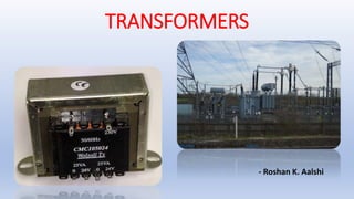
- 1. TRANSFORMERS - Roshan K. Aalshi This Photo by Unknown Author is licensed under CC BY-SA
- 2. INTRODUCTION What is a Transformer? • A transformer is a device used in the power transmission of electric energy. The transmission current is AC. It is commonly used to increase or decrease the supply voltage without a change in the frequency of AC between circuits. The transformer works on basic principles of electromagnetic induction and mutual induction. • The transformer is basically a voltage control device that is used widely in the distribution and transmission of alternating current power. The idea of a transformer was first discussed by Michael Faraday in the year 1831 and was carried forward by many other prominent scientific scholars. However, the general purpose of using transformers was to maintain a balance between the electricity that was generated at very high voltages and consumption which was done at very low voltages.
- 3. WORKING PRINCIPLE • The transformer works on the principle of Faraday’s law of electromagnetic induction and mutual induction. • There are usually two coils primary coil and secondary coil on the transformer core. The core laminations are joined in the form of strips. The two coils have high mutual inductance. When an alternating current pass through the primary coil it creates a varying magnetic flux. • As per faraday’s law of electromagnetic induction, this change in magnetic flux induces an emf (electromotive force) in the secondary coil which is linked to the core having a primary coil. This is mutual induction.
- 4. FARADAY’S PRINCIPLE • According to the figure, the formation of varying magnetic flux lines around a wire- wound. • The interesting part is that reverse is also true, when a magnetic flux line fluctuates around a piece of wire, a current will be induced in it. This was what Michael faraday found in 1831 which is the fundamental working principle of electric generators as well as transformers.
- 5. Parts of a Single phase transformer Core: • The core acts as a support to the winding in the transformer. • It also provides a low reluctance path to the flow of magnetic flux. The winding is wound on the core as shown in the picture. • It is made up of a laminated soft iron core in order to reduce the losses in a transformer. The factors such as operating voltage, current, power etc decide core composition. • The core diameter is directly proportional to copper losses and inversely proportional to iron losses.
- 6. Windings: • Windings are the set of copper wires wound over the transformer core. Copper wires are used due to the high conductivity of copper minimizes the loss in a transformer because when the conductivity increases, resistance to current flow decreases. • The high ductility of copper is the property of metals that allows it to be made into very thin wires. • There are mainly two types of windings. Primary windings and secondary windings. • Primary winding: The set of turns of windings to which supply current is fed. • Secondary winding: The set of turns of winding from which output is taken. • The primary and secondary windings are insulated from each other using insulation coating agents.
- 7. Insulation Agents: • Insulation is necessary for transformers to separate windings from each other and to avoid short circuit. This facilitates mutual induction. Insulation agents have an influence on the durability and the stability of a transformer. • Following are used as an insulation medium in a transformer: Insulating oil Insulating tape Insulating paper Wood-based lamination
- 8. Some Important Terms Voltage Transformation Ratio: K is called the voltage transformation ratio, which is a constant. Case1: if N2 > N1, K>1 it is called a step-up transformer. Case 2: if N2< N1, K<1 it is called a step-down transformer Transformer Efficiency: The system is called better when its efficiency is high. %Efficiency(η)= (Output power/ Input power) ✕ 100 Efficiency is always less than 100% due to following reasons: • Copper loss • Eddy current loss • Hysteresis loss
- 9. TYPES OF TRANSFORMERS Transformers are used in various fields like power generation grid, distribution sector, transmission and electric energy consumption. There are various types of transformers which are classified based on the following factors; Working voltage range The medium used in the core Winding arrangement Installation location
- 10. Based on Voltage Levels Commonly used transformer type, depending upon voltage they are classified as: • Step-up Transformer: They are used between the power generator and the power grid. The secondary output voltage is higher than the input voltage. • Step down Transformer: These transformers are used to convert high voltage primary supply to low voltage secondary output.
- 11. Based on the Medium of Core Used • Air core Transformer: The flux linkage between primary and secondary winding is through the air. The coil or windings wound on the non-magnetic strip. • Iron core Transformer: Windings are wound on multiple iron plates stacked together, which provides a perfect linkage path to generate flux
- 12. Based on Install Location • Power Transformer: It is used at power generation stations as they are suitable for high voltage application • Distribution Transformer: Mostly used at distribution lanes for domestic purposes. They are designed for carrying low voltages. It is very easy to install and characterized by low magnetic losses. • Measurement Transformers: These are further classified. They are mainly used for measuring voltage, current, power. • Protection Transformers: They are used for component protection purposes. In circuits, some components must be protected from voltage fluctuation etc. Protection transformers ensure component protection. Also, there are Audio frequency transformers, Radio frequency transformers, Intermediate frequency transformers, Autotransformers, etc.
- 13. APPLICATIONS • Transformers with multiple secondary’s are used in radio and TV receiver which require several different voltages. • Transformers are used as voltage regulators. • Transformer transmits electrical energy through wires over long distances