SlideShare ist ein Scribd-Unternehmen logo
1 von 28
funded by
Chapter C : Predesign – system sizing
Speaker: XXXX YYYYY
Training course on solar cooling
Chapter C : Predesign – system sizing 2
System sizing
Convection
Hygienic air
Internal load
Irradiance
Source : TECSOL
A) Building load characterisation needed
Chapter C : Predesign – system sizing 3
System sizing
Internal loads
Chapter C : Predesign – system sizing 4
System sizing
Chapter C : Predesign – system sizing 5
Solar collectors and thermally driven cooling
desiccant
adsorpti
on 1-effect
absorpti
on
2-effect
absorpti
on
SAC = solar air
coll.
CPC = stationary
CPC
FPC = selectively
coated flat plate
EHP = evacuated
heat-pipe
EDF = evacuated,
direct flow
SYC = stationary
concentrated,
Sydney-type
SAC = solar air
coll.
CPC = stationary
CPC
FPC = selectively
coated flat plate
EHP = evacuated
heat-pipe
EDF = evacuated,
direct flow
SYC = stationary
concentrated,
Sydney-type
0.0
0.1
0.2
0.3
0.4
0.5
0.6
0.7
0.8
0.9
1.0
0.00 0.05 0.10 0.15 0.20 0.25 0.30 0.35
∆T/G [Km
2
/W]
ηcoll
SYC
EDF
FPC
SAC
EHP
CPC
Source : Fraunhofer ISE
A) Choice of technologies
Chapter C : Predesign – system sizing 6
Solar production
0 25 50 75 100 125 150 175
0,0
0,1
0,2
0,3
0,4
0,5
0,6
0,7
0,8
0,9
flat-plate
evac. tube
evac. flat-plate
CPC-collector
parabolic trough
Irradiation:
800 W/m² direct normal
200 W/m² diffuse
efficiency
T - TAMB
[K] 60 80 100 120 140 160 180 200
0
100
200
300
400
500
600
700
800
900
1000
Barcelona
energyyield[kWh/m²]
temperature [°C]
FPC
EFPC
ETC
CPC
PTC
60 80 100 120 140 160 180 200
0
100
200
300
400
500
600
700
800
900
1000
Huelva
energyyield[kWh/m²]
temperature [°C]
FPC
EFPC
ETC
CPC
PTC
FPC: flate plate collector
EFPC: flate plate collector with concentrating parabolic compound (CPC)
ETC: vaccum tube collectors
CPC: vaccum tube collectors with concentrating parabolic compound (CPC)
PTC: parabolic trough collector
Source : Aiguasol
Chapter C : Predesign – system sizing 7
ProducedCold
rFactoConversion
ConsumedEnergyalConvencion
PEspec =
conveleccold
elec
eleccoldelec
elec
cold
elec
elec
conv,spec
COP
1
Q
Q1
Q
1Q
Q
Q
PE
εεε
ε
====
Specific Primary Energy (PE) (KWh PE/KWh cold):
Conversion factor: Electricity – 0.36; Fossil Fuel – 0.9
Conventional Compression Chiller:
Source : INETI
Primary energy analysis
Definitions
Chapter C : Predesign – system sizing 8
towercooling,spec
thermalfossil
sol
towercooling,spec
cold
heatdriving
fossil
sol
towercooling,spec
coldfossil
solheatdriving
towercooling,spec
coldfossil
backup
towercooling,spec
cold
fossil
backup
solar,spec
PE
COP.
)F-(1
PE
Q
Q)F-(1
PE
Q
1)F-(1Q
PE
Q
1Q
PE
Q
Q
PE
+=
+=
+=
+=
+=
ε
ε
ε
ε
ε
heatdriving
cold
thermal
Q
Q
COP =






+=
+
=
==
thermalelect
ercoolingtowspec,
cold
coldtdrivinghea
elect
ercoolingtowspec,
coldelect
edheatrejectercoolingtowspec,
cold
elect
ercoolingtow
ercoolingtow,spec
COP
1
1
E
Q
)QQ(E
Q
1QE
Q
E
PE
ε
ε
ε
ε
Solar Thermal Driven Chiller:
With:
Cooling tower:
Source : INETI
Primary energy analysis
Definitions
Chapter C : Predesign – system sizing 9
0.0
0.5
1.0
1.5
2.0
2.5
0 0.1 0.2 0.3 0.4 0.5 0.6 0.7 0.8 0.9 1
Solar Fraction for cooling
PEspec,sol,kWhPE/kWhcold
COP = 0.6
COP = 0.8
COP = 1.0
COP = 1.2
Conv 2
Conv, 1
Primary energy analysis
COPconv =
2.5
COPconv =
4.5
heat source:
solar collector
+ fossil fueled
backup
primary
energy
conversion
factor for
electricity:
0.36
primary
energy
conversion
factor for
fossil fuels: 0.9
heat source:
solar collector
+ fossil fueled
backup
primary
energy
conversion
factor for
electricity:
0.36
primary
energy
conversion
factor for
fossil fuels: 0.9
Source : Fraunhofer ISE
Chapter C : Predesign – system sizing 10
Comparison between absortion and compression
Efficiency based on primary energy
0 0.1 0.2 0.3 0.4 0.5 0.6 0.7 0.8 0.9 1
solar fraction cooling
0
0.5
1
1.5
2
specific primary energy per unit of cold
conventional system
thermal system,
low COP
thermal system,
high COP
no primary
energy
saving
saves primary
energy
Source : Aiguasol
Chapter C : Predesign – system sizing 11
! High solar fraction for cooling necessary for solar thermally driven cooling
equipment with low COP which use a fossil fueled backup
! A lower solar fraction is acceptable if thermally driven cooling equipment with a
higher COP is employed
! An alternative is to use a conventional chiller as a backup (e.g. in case of a large
overall cooling power)
! Primary energy savings are always achieved using a solar thermally autonomous
systems but no guarantee for strictly keeping desired indoor comfort limits can
be given
! In any case the use of the solar collector should be maximised by supplying heat
also to other loads such as the heating system or hot water production
Consequences of primary energy performance
Chapter C : Predesign – system sizing 12
Design
Design with regard to solar-assisted air-conditioning mainly means
! Selection of the proper thermally driven cooling equipment for the
selected air-conditioning system
! Selection of the proper type of solar collectors for the selected air-
conditioning system and thermally driven cooling equipment
! Sizing of the solar collector field and other components of the solar
system with regard to energy and cost performance
Chapter C : Predesign – system sizing 13
Design approaches
‚Rules of thumb‘
Collector cost per heating
capacity
Cost of solar heat for
given climate
Load - gain - analysis for
given climate and load
Anual cost based on load-
gain-analysis
Computer design tool with
predefined systems
Open simulation platform
Accuracy,reliabilityofresults,detailsofdesigninformation
Requiredsysteminformation,effortforparametrization
Source : Fraunhofer ISE
Chapter C : Predesign – system sizing 14
Design point
design
design,cold
design,collcollcoll
COP
P
GA =η⋅⋅
==
>
designdesign,collcoll
spec
COPG
1
A
⋅η⋅
=
Example Gcoll = 800 W/m2
hcoll,design = 0.5
COPdesign = 0.7
==> Aspec = 3.57 m2
per kW cooling power
Source : Fraunhofer ISE
Chapter C : Predesign – system sizing 15
+ Method allows a very quick assessment (guess) about the
required collector area, if the efficiency of the collector and
the COP of the thermally driven cooling equipment is
known
– Method neglects completely the influence of the variation
of radiation on the collector during day and year
– Any information on the specific site and load is neglected
– Method neglects completely part load conditions of cooling
load in thermally driven cooling equipment
Advantages and disadvantages
Chapter C : Predesign – system sizing 16
Sizing
Source : EAW
Average values of the
specific collector area
" for Absorption- and
Adsorption chillers
3,0 to 3,5 m²/kW
chilling capacity
" for open technologies
(DEC, liquid DEC):
8 to 10 m² per 1.000 m³/h
rated air flowrate
Chapter C : Predesign – system sizing 17
Collector first cost
⊥⊥
−
⋅−
−
⋅−⋅Θ=η
G
)TT(
c
G
)TT(
cc)(k
2
ambav
2
ambav
10
⊥⊥
⊥
⋅η
=⇒
⋅η
=⇒⋅η⋅=
G
kW1
A
G
Q
AGAQ spec
use
use
&
&
specspecpower,heat CostACost ⋅=
incident
angle
modifier
optical
efficiency
linear
heat loss
coeff.
quadr.
heat loss
coeff.
average fluid
temperature
ambient air
temperature
radiation on
collector
specific
collector cost
Source : Fraunhofer ISE
average fluid temperature = operating hot temperature of cooling system
Chapter C : Predesign – system sizing 18
Collector cost versus specific required area
0
400
800
1200
1600
2000
1 2 3 4 5 6
required absorber area [m2
/kW]
collectorfirstcost[€/kW]
evacuated tube flat plate flat plate - integrated roof stationary CPC
Tav = 75°C
Gcoll = 800 W/m2
Source : Fraunhofer ISE
Chapter C : Predesign – system sizing 19
Advantages and disadvantages
+ Method allows a rough comparison of different solar
collectors, if the collector parameters and the operation
temperature of the thermally driven cooling equipment are
known
– Method neglects completely the influence of the variation
of radiation on the collector during day and year
– Any information on the specific site and load is neglected
– Method neglects completely part load of cooling load and
thermally driven cooling equipment
Chapter C : Predesign – system sizing 20
Solar heat cost
annuityspecannual fCostCost ⋅=
gross
annual
heat
Q
Cost
Cost =
annual
collector cost
spedific
collector cost
(€/m2
)
annuity
factor
solar heat
cost (€/kWh
of heat)
collector gross
heat
production
.dataicallogmeteoroatingmindotheofvalueshourlygsinucalculatedTypically
.etemperaturoperationgivenaandsitegivenaatproductionheatcollectorannualQgross =
Source : Fraunhofer ISE
Chapter C : Predesign – system sizing 21
Solar heat cost
0
4
8
12
16
20
0 200 400 600 800 1000 1200 1400
annual gross heat production [kWh/m2
]
heatcost[€-cent/kWh]
etc fpc irc cpc Palermo, Tav = 75°C
Source : Fraunhofer ISE
Chapter C : Predesign – system sizing 22
Solar heat cost
0
4
8
12
16
20
0 200 400 600 800 1000 1200 1400
annual gross heat production [kWh/m2
]
heatcost[€-cent/kWh]
etc fpc irc cpc Palermo, Tav = 95°C
Source : Fraunhofer ISE
Chapter C : Predesign – system sizing 23
Simple software tool SHC (NEGST project)
Only needs monthly cooling (heating) load
Free download in:
http://www.swt-technologie.de/html/publicdeliverables3.html
Compares monthly loads
(heating and coling) with
monthly solar energy
gains.
It is based on
PHIBARFCHART Method
- The results are primary
energy savings for
colector area installed.
Chapter C : Predesign – system sizing 24
Advantages and disadvantages
+ Method allows a good comparison of different solar
collectors using their parameters and the radiation data of
a specific site
+ The maximum possible heat production of a specific solar
collector for a given site (annual meteorological data file)
and a given constant operation temperature is determined
– Any information about the load profile is neglected
– Method neglects completely part load of cooling load and
thermally driven cooling equipment
Chapter C : Predesign – system sizing 25
meteo data
building
model
collector
model
solar fractions for
heating and cooling
COP, ε
heatload
solar gains
0
50
100
150
200
250
0 100 200 300 400 500 600 700 800
heating cooling 1 0.5 0.25 0.1
! For each hour of the year
the required heat for
cooling (heating) is
computed, e.g. using
building simulation
! Global efficiency factors for
transformation of heat in
cooling (heating) are used
to describe the technical
equipment
! Calculation of hourly
collector gains using
different operation
temperatures for cooling
and heating
Correlation of loads and gains
Source : Fraunhofer ISE
Chapter C : Predesign – system sizing 26
Software tools needed to determine hourly
cooling (heating) loads of a building
TRNSYS – Commercially available
(www.sel.me.wisc.edu/trnsys/)
Energy plus – Download free
(www.eere.energy.gov/buildings/energyplus/ )
ESP-r – Download free
(http://www.esru.strath.ac.uk/Programs/ESP-r.htm )
A list of other software tools can be found :
(http://www.eere.energy.gov/buildings/tools_directory/)
Chapter C : Predesign – system sizing 27
Simple software tools using hourly
cooling (heating) load
SACE Cooling evaluation light tool
– available in http://www.solair-project.eu/218.0.html
Results using this software tool while be shown latter
Chapter C : Predesign – system sizing 28
Simple software tools using hourly
cooling (heating) load
SolAC – available in:
http://www.iea-shc-task25.org/english/hps6/index.html
Four different units are considered in this software:
• Solar system
• Cooling device
• Air handling unit
• Cooling and heating components in the room
The input data for the
programme is:
• weather data including solar
radiation (hourly data)
• load files including heating
and cooling loads (hourly
data)
Chapter C : Predesign – system sizing 29
Dynamic simulation software tools using
hourly cooling (heating) load
- System orientated
TNSYS - www.sel.me.wisc.edu/trnsys/
ColSim - www.colsim.de
Insel - http://www.inseldi.com/index.php?id=21&L=1
- Building Orientated
Energy plus - www.eere.energy.gov/buildings/energyplus/
Software Solar
Components
AC
Components
New
Components
Free
downlaod
Open
source
code
TRNSYS Yes Yes Yes No Yes
ColSim Yes Yes, but no
clear list was
possible to
obtain.
Yes Not clear Yes
Energy
Plus
Yes Yes Yes Yes Not clear
INSEL Yes Yes Yes NO NO
Chapter C : Predesign – system sizing 30
Identification of HVAC components available which are most interesting for
CTSS
TRNSYS 16.
Type 107 – Absorption Chiller (hot water fired, single effect)
Type 51 – Cooling Towers.
TESS Libraries
Type 680 – Single-effect hot water-fired absorption chiller (Equivalent to type
107 of TRNSYS 16)
Type 679 – Single-effect steam-fired absorption chiller
Type 677 – Double-effect hot water-fired absorption chiller
Type 676 – Double-effect steam-fired absorption chiller
Type 683 – Rotary desiccant dehumidifier – models a rotary dessicant
dehumidifier containing nominal silica gel.
Chapter C : Predesign – system sizing 31
solar
gas
elect
caldera
bomba
calor
absorció
calefacció
refrigeració
solar
gas
elect
caldera
bomba
calor
absorció
calefacció
refrigeració
Source : Aiguasol
Calculation methods :
Estimated calculation with energy balances
Solar thermal energy availability
• Simulation tool for the solar systems
• “Infinite” consumption with high return temperature (chilled water)
• 100% use of produced solar energy
Energy load determination, per year and per month: cold, heat, and DHW
• Calculation tool for the building energy load
• DHW energy load determination
Use factor determination
• Depends on the relation availability / load
• Depends on the heat storage
Definition of energy flows between subsystems
• -> Definition of a control strategy
Chapter C : Predesign – system sizing 32Source : Fraunhofer ISE
Chapter C : Predesign – system sizing 33
Guidelines for design, control & operation
of solar assisted adsorption chillers
0
0.1
0.2
0.3
0.4
0.5
0.6
0.7
60 65 70 75 80 85 90 95
temperature, °C
COP,COPsol,etacoll
20
30
40
50
60
70
80
90
coolingpower,kW
etacoll COP
COPsol cooling power
COPsol =
COP * ηcoll
Radiation on
collector: 800 W/m
2
COPsol =
COP * ηcoll
Radiation on
collector: 800 W/m
2
COP-maximum
at about 70°C
Source : Fraunhofer ISE
Chapter C : Predesign – system sizing 34
Efficiency of solar thermal cooling systems
0.00
0.10
0.20
0.30
0.40
0.50
0.60
60 80 100 120 140 160 180 200
Working temperature [°C]
COPsolar
500
600
700
800
900
1000
Irradiation W/m2
==> optimal
working
temperature
depends on the
irradiation level
Source : Fraunhofer ISE
Chapter C : Predesign – system sizing 35
Evaluation parameter: Costs of saved
primary energy
! Combined Energy-costs-Performance
! enables comparison of different system designs
Costs of primary
energy saved
=
∆ Total annual costs
∆ Primary energy
∆primary energy = annual primary energy saving of
the solar driven system compared to a
conventional reference system
∆primary energy = annual primary energy saving of
the solar driven system compared to a
conventional reference system
∆total annual costs = annual supplementary costs of the solar
driven system compared to a
conventional reference system
∆total annual costs = annual supplementary costs of the solar
driven system compared to a
conventional reference system
Source : Fraunhofer ISE
Chapter C : Predesign – system sizing 36
10%
20%
30%
40%
50%
60%
55 65 75 85 95 105 115 125 135
Storage volume, l/m
2
Primaryenergysaved
160 180 200 220 240 260 280
! Madrid
! Office
buildings
! Flat plate
collector
! Backup:
Gas boiler
! Absorption
chiller
Collector surface,
m2
Example: primary energy savings
(in%ofthereferencesystem)
Growing collector
surface
Source : Fraunhofer ISE
Chapter C : Predesign – system sizing 37
140%
145%
150%
155%
160%
165%
170%
175%
180%
55 65 75 85 95 105 115 125 135
Speichervolumen, l/m2
Jahreskosten,%Referenz
160 180 200 220 240 260 280
Kollektorfläche,
m2
ansteigende
Kollektorfläche
Example: annual costs
! Madrid
! Bürogebäude
! Flachkollektor
! Backup:
Gaskessel
! Absorptions-
kältemaschine
! Madrid
! Office
buildings
! Flat plate
collector
! Backup:
Gas boiler
! Absorption
chiller
Growing collector
surface
Collector surface,
m2
Storage volume l/m2
Annualcosts,%reference
Source : Fraunhofer ISE
Chapter C : Predesign – system sizing 38
0.12
0.14
0.16
0.18
0.2
0.22
0.24
0.26
0.28
55 65 75 85 95 105 115 125 135
Speichervolumen, l/m2
KosteneingespartePE,€/kWh
160 180 200 220 240 260 280
Kollektorfläche,
m2
Minimu
m
Example: Costs of primary energy savings
! Madrid
! Bürogebäude
! Flachkollektor
! Backup:
Gaskessel
! Absorptions-
kältemaschine
! Madrid
! Office
buildings
! Flat plate
collector
! Backup:
Gas boiler
! Absorption
chiller
Storage volume l/m2
Collector surface,
m2
Costsofprimaryenergysaved,€/kWh
Source : Fraunhofer ISE
Chapter C : Predesign – system sizing 39
Dynamic modelling with TRNSYS… necessary
System sizing
Chapter C : Predesign – system sizing 40
Transient simulation – TRNSYS
TRNSYS features
– Numerical calculation methods
– Continuous yearly simulation of the thermal behaviour of the
installation, analysing the transitory phenomenon of the heat
flows
– Variability of climatology (temperature, irradiation) is taken into
account
– Enables analysis of the different factors which determine the
energetic behaviour of the system # parametric study#
optimisation
Chapter C : Predesign – system sizing 41
TRNSYS Workspace
Transient simulation – TRNSYS
Chapter C : Predesign – system sizing 42
Results obtained with TRNSYS
Transient simulation – TRNSYS
Chapter C : Predesign – system sizing 43
Analysis of the results
0
5
10
15
20
25
30
35
1 14 27 40 53 66 79 92 105 118 131 144 157
Tamb
Tair
0
1000
2000
3000
4000
5000
6000
7000
Gener Febrer Març Abril Maig Juny Juliol Agost Setembre Octubre NovembreDesembre
kWh
Monthly heating demand in kWh
Total demand in kWh
Solar contribution in kWh
Transient simulation – TRNSYS
Chapter C : Predesign – system sizing 44
Calculation options with dynamic simulation tools
Separated calculation of building and cooling system
– Step 1: Simulation of the building demand (heating, cooling)
– Cooling system model= ideal system with infinite power.
– Intermediate result: hourly data of heating and cooling demand.
– Step 2: Simulation of the cooling system
– Result: energy contribution of the real cooling system
Coupled calculation of the building and the cooling system
– Simulation of the building (demand) and of the cooling system in the
same software
– Cooling system model = real system
– Results:
• Energy contribution of the real cooling system
• Degree of fulfilment of the comfort criteria
Transient simulation – TRNSYS
Chapter C : Predesign – system sizing 45
Which questions have to be answered?
1. Which is the basic sizing of the main equipments?
• Collector field : type and size in m2
• Absorption machine: kWf
2. What is the solar contribution to the cooling, heating and global demand?
3. Which is the basic sizing of the back-up system?
• type (boiler, heat pump, air conditioner...);
• size kW
4. Which are the energy savings?
5. What are the additional costs compared to a conventional installation?
6. What is the pay-back time?
Chapter C : Predesign – system sizing 46
Chapter C : Predesign – system sizing 47
Sizing of the absorption machine
f
f
solar
gensolar
gen
f
kW
m
m
kW
kW
kW
m
kW
kW
kW 2
22
332.015.065.0 ==××
Demand peak < maximal total power (absorption + auxiliaries) + cold
storage
Operating with solar energy: minimal power required to absorb the
solar heat produced and convert it into cold. # 3 m2/kWf
– Criteria 1: the absorption machine is able to use the maximal
solar production. Solar peak production approx. 0.5 kW/m2
(1000 W/m² x 50 % efficiency)
– Criteria 2: the solar energy produced during the day of maximal
irradiation can be totally used by the absorption machine,
assuming that the required heat storage is available
– Maximal power to guarantee a minimal solar contribution
(typically > 60...70 %) and/or an reasonable number of operating
hours (> 1000 h/year).
Rules of Thumb – pre-design rules of
solar cooling systems
Chapter C : Predesign – system sizing 48
Sizing of the heat/cold storage
Cold storage
– Cover demand peaks (smaller machines, larger number of
operating hours)
– Avoid part-load or intermittent operation
Heat storage
– Gap between cooling demand and solar heat availability
– Guarantee continuous operation of the machine during days of
intermittent irradiation
– Typical size: 25 .. 50 litres / m2 of collector
Rules of Thumb – pre-design rules of
solar cooling systems
Chapter C : Predesign – system sizing 49
Control strategy
Starting priority (cold production) according to the energy efficiency
– Cold production with heat-pump in case of simultaneous heat
demand. Solar contribution for space heating.
– Cold production with absorption through solar heat
– Cold production with heat-pump (without heat recovery)
– Cold production with absorption through gas boiler
Rules of Thumb – pre-design rules of
solar cooling systems
Chapter C : Predesign – system sizing 50
System sizing
75 – 95°C
75 – 95°C
25 - 35°C
7 – 12 °C
700W/m² 85 kW
77 kW
50
kWf
127 kW
200 m²
Source : TECSOL
Chapter C : Predesign – system sizing 51
System sizing
! 1 Cooling load : 50 kWc
! 2 Inlet generator : 50 / 0.65 = 77 kW
! 3 Cooling tower : 77 + 50 = 127 kW
! 4 Primary loop efficiency : 0.9
! 5 Heat load on collector side : 85 kW
! 6 Average irradiance : 700 W/m²
! 7 Collector efficiency : 0.6
! 8 Collector area : 85/0.7/0.6 = 200 m²
! 9 Optimal tilt : 30° (France South)
! 10 Groung space necessary > 300 m²
Chapter C : Predesign – system sizing 52
Check list concept : example
233
Possible undersizement of solar system thanks to
back up
333Passives actions decrease potential
223Yearly heating and DHW needs
223Yearly adequation production <-> load
133Daily adequation production <-> load
Load
TECHNICAL
FEASIBILITY
333Adapted existing material (or planned) for back up
233Adapted distribution network
123Space for technical premices
223Important area for solar collection
333Climate
Building
HotelPublic buildingIndustry
Source : TECSOL
Chapter C : Predesign – system sizing 53
455558
TOTAL SCORE
(on 63) :
232Presence of a long term financed monitoringMonitoring
223Regulat operation action possibilitiesFEASIBILITY
223Skilled internal technical staff
O&M
ORGANISAT.
133Financial stability of building owner
231National & international supports eligibility
333Environmental action politics
323Importance in term of marketing impactFEASIBILITY
333Building owner motivationECONOMICAL
133High investment capacity
Building owner
223Low water cost
331High cost of saved energy
Cost of energy
HotelPublic buildingIndustry
Check list concept : example
Source : TECSOL
Chapter C : Predesign – system sizing 54
Disclaimer
This training has been developed in the context of SOLAIR. SOLAIR is a European co-
operation project for increasing the market implementation of solar-air-conditioning
systems for small and medium applications in residential and commercial buildings. For
further information on the project or on products of the project see: www.solair-
project.eu
The project SOLAIR is supported by the Intelligent Energy – Europe (IEE) programme of
the European Union promoting energy efficiency and renewables. More details on the
IEE programme can be found on: http://ec.europa.eu/energy/intelligent/index_en.html
The sole responsibility for the content of this training lies with the authors. It does not
represent the opinion of the European Communities. The European Commission is not
responsible for any use that may be made of the information contained therein.
Note – This presentation is not owned by RE-Docs. It has simply been shared for wider
dissemination because of its useful content. The author have been clearly acknowledged on
www.redocs.co In case of any issues you may contacts us at www.redocs.co/contact
Visit us on
www.redocs.co
your personal library on RE
Hope you found the presentation useful!
for similar useful material

Weitere ähnliche Inhalte

Was ist angesagt?

MEC441 - Solar Panel Cooling System
MEC441 - Solar Panel Cooling SystemMEC441 - Solar Panel Cooling System
MEC441 - Solar Panel Cooling System
Luis Lituma
 
THERMAL POWER CYCLES AND THEIR APPs
THERMAL POWER CYCLES AND THEIR APPsTHERMAL POWER CYCLES AND THEIR APPs
THERMAL POWER CYCLES AND THEIR APPs
Prateek Sharma
 
Energia solar thermal energy storage systems
Energia solar   thermal energy storage systemsEnergia solar   thermal energy storage systems
Energia solar thermal energy storage systems
Usama Abudawud
 
Experimental analysis of a flat plate solar collector with integrated latent ...
Experimental analysis of a flat plate solar collector with integrated latent ...Experimental analysis of a flat plate solar collector with integrated latent ...
Experimental analysis of a flat plate solar collector with integrated latent ...
Journal of Contemporary Urban Affairs
 

Was ist angesagt? (20)

Direct steam generation from solar
Direct steam generation from solarDirect steam generation from solar
Direct steam generation from solar
 
solar vapour absourtion system
solar vapour absourtion systemsolar vapour absourtion system
solar vapour absourtion system
 
MEC441 - Solar Panel Cooling System
MEC441 - Solar Panel Cooling SystemMEC441 - Solar Panel Cooling System
MEC441 - Solar Panel Cooling System
 
ENER-G Heat pump technology CPD
ENER-G Heat pump technology CPD ENER-G Heat pump technology CPD
ENER-G Heat pump technology CPD
 
Heat pump presentation
Heat pump presentation Heat pump presentation
Heat pump presentation
 
Thermal Efficiency of Buildings - Stefan Huber - Paul Heat Recovery Scotland
Thermal Efficiency of Buildings - Stefan Huber - Paul Heat Recovery ScotlandThermal Efficiency of Buildings - Stefan Huber - Paul Heat Recovery Scotland
Thermal Efficiency of Buildings - Stefan Huber - Paul Heat Recovery Scotland
 
Air Source Heat Pumps - Thomas Dickson - Glow Worm
Air Source Heat Pumps - Thomas Dickson - Glow WormAir Source Heat Pumps - Thomas Dickson - Glow Worm
Air Source Heat Pumps - Thomas Dickson - Glow Worm
 
ORC - Organic Rankine Cycle technology for biomass and EfW cogeneration and t...
ORC - Organic Rankine Cycle technology for biomass and EfW cogeneration and t...ORC - Organic Rankine Cycle technology for biomass and EfW cogeneration and t...
ORC - Organic Rankine Cycle technology for biomass and EfW cogeneration and t...
 
ORC ElectraTherm Green Machine - waste heat to power, Power generation
ORC ElectraTherm Green Machine - waste heat to power, Power generationORC ElectraTherm Green Machine - waste heat to power, Power generation
ORC ElectraTherm Green Machine - waste heat to power, Power generation
 
11 mn01 review 3
11 mn01 review 311 mn01 review 3
11 mn01 review 3
 
Presentation 2
Presentation 2Presentation 2
Presentation 2
 
THERMAL POWER CYCLES AND THEIR APPs
THERMAL POWER CYCLES AND THEIR APPsTHERMAL POWER CYCLES AND THEIR APPs
THERMAL POWER CYCLES AND THEIR APPs
 
Heat pumps - An Introduction
Heat pumps - An IntroductionHeat pumps - An Introduction
Heat pumps - An Introduction
 
SolarWall®
SolarWall® SolarWall®
SolarWall®
 
Energia solar thermal energy storage systems
Energia solar   thermal energy storage systemsEnergia solar   thermal energy storage systems
Energia solar thermal energy storage systems
 
Solar collector
Solar collectorSolar collector
Solar collector
 
Organic Rankine Cycle
Organic Rankine CycleOrganic Rankine Cycle
Organic Rankine Cycle
 
Building Energy 2014: PV and Heat Pumps by Fortunat Mueller
Building Energy 2014: PV and Heat Pumps by Fortunat MuellerBuilding Energy 2014: PV and Heat Pumps by Fortunat Mueller
Building Energy 2014: PV and Heat Pumps by Fortunat Mueller
 
Gould - Thermal Energy Storage
Gould - Thermal Energy StorageGould - Thermal Energy Storage
Gould - Thermal Energy Storage
 
Experimental analysis of a flat plate solar collector with integrated latent ...
Experimental analysis of a flat plate solar collector with integrated latent ...Experimental analysis of a flat plate solar collector with integrated latent ...
Experimental analysis of a flat plate solar collector with integrated latent ...
 

Andere mochten auch

Solar space heating and cooling
Solar space heating and coolingSolar space heating and cooling
Solar space heating and cooling
Aniket Gavali
 
Cooling applications of solar system ppt
Cooling applications of solar system pptCooling applications of solar system ppt
Cooling applications of solar system ppt
vikramdangi
 
Cmos design
Cmos designCmos design
Cmos design
Mahi
 
Solar Air Conditioner
Solar Air ConditionerSolar Air Conditioner
Solar Air Conditioner
skullcrusher
 
Cooling system
Cooling systemCooling system
Cooling system
Ajay Yadav
 

Andere mochten auch (17)

Solar Cooling
Solar CoolingSolar Cooling
Solar Cooling
 
Solar heating and cooling system
Solar heating and cooling systemSolar heating and cooling system
Solar heating and cooling system
 
Satish resume
Satish resumeSatish resume
Satish resume
 
13. andré de herde shc - solar heating and cooling
13. andré de herde   shc - solar heating and cooling13. andré de herde   shc - solar heating and cooling
13. andré de herde shc - solar heating and cooling
 
The Solar Cooling
The Solar CoolingThe Solar Cooling
The Solar Cooling
 
Solar heating and cooling
Solar heating and coolingSolar heating and cooling
Solar heating and cooling
 
Non trad
Non tradNon trad
Non trad
 
Solar space heating and cooling
Solar space heating and coolingSolar space heating and cooling
Solar space heating and cooling
 
Cooling applications of solar system ppt
Cooling applications of solar system pptCooling applications of solar system ppt
Cooling applications of solar system ppt
 
Active and Passive Solar Energy System
Active and Passive Solar Energy SystemActive and Passive Solar Energy System
Active and Passive Solar Energy System
 
Cmos design
Cmos designCmos design
Cmos design
 
Solar Air Conditioner
Solar Air ConditionerSolar Air Conditioner
Solar Air Conditioner
 
Solar refrigeration
Solar refrigerationSolar refrigeration
Solar refrigeration
 
Solar energy power point presentation
Solar energy power point presentation Solar energy power point presentation
Solar energy power point presentation
 
Cooling system
Cooling systemCooling system
Cooling system
 
12 Cooling Load Calculations
12 Cooling Load Calculations12 Cooling Load Calculations
12 Cooling Load Calculations
 
HVAC Cooling Load Calculation
HVAC Cooling Load CalculationHVAC Cooling Load Calculation
HVAC Cooling Load Calculation
 

Ähnlich wie Sizing of solar cooling systems

A solar ejector cooling system using refrigerant r141b
A solar ejector cooling system using refrigerant r141bA solar ejector cooling system using refrigerant r141b
A solar ejector cooling system using refrigerant r141b
Mark Murray
 
A Solar Ejector Cooling System Using Refrigerant R141b
A Solar Ejector Cooling System Using Refrigerant R141bA Solar Ejector Cooling System Using Refrigerant R141b
A Solar Ejector Cooling System Using Refrigerant R141b
Mark Murray
 
Welcome to International Journal of Engineering Research and Development (IJERD)
Welcome to International Journal of Engineering Research and Development (IJERD)Welcome to International Journal of Engineering Research and Development (IJERD)
Welcome to International Journal of Engineering Research and Development (IJERD)
IJERD Editor
 
ICEEE Poster_YoannGuinard
ICEEE Poster_YoannGuinardICEEE Poster_YoannGuinard
ICEEE Poster_YoannGuinard
Yoann Guinard
 
Dynamic modeling, simulation of a small wind fuel cell hybrid
Dynamic modeling, simulation of a small wind fuel cell hybridDynamic modeling, simulation of a small wind fuel cell hybrid
Dynamic modeling, simulation of a small wind fuel cell hybrid
Rajesh Kumar Sahu
 

Ähnlich wie Sizing of solar cooling systems (20)

001 160718 energy systems for green buildings20160718-2
001 160718 energy systems for green buildings20160718-2001 160718 energy systems for green buildings20160718-2
001 160718 energy systems for green buildings20160718-2
 
GSA TUNED HIGH EXERGY IN PV ARRAY
GSA TUNED HIGH EXERGY IN PV ARRAYGSA TUNED HIGH EXERGY IN PV ARRAY
GSA TUNED HIGH EXERGY IN PV ARRAY
 
The “White Certificates” scheme – Examples of Monitoring &Verification Processes
The “White Certificates” scheme – Examples of Monitoring &Verification ProcessesThe “White Certificates” scheme – Examples of Monitoring &Verification Processes
The “White Certificates” scheme – Examples of Monitoring &Verification Processes
 
A solar ejector cooling system using refrigerant r141b
A solar ejector cooling system using refrigerant r141bA solar ejector cooling system using refrigerant r141b
A solar ejector cooling system using refrigerant r141b
 
A Solar Ejector Cooling System Using Refrigerant R141b
A Solar Ejector Cooling System Using Refrigerant R141bA Solar Ejector Cooling System Using Refrigerant R141b
A Solar Ejector Cooling System Using Refrigerant R141b
 
C lorenzo energies_04114'20
C lorenzo energies_04114'20C lorenzo energies_04114'20
C lorenzo energies_04114'20
 
poster_7_17_BC3
poster_7_17_BC3poster_7_17_BC3
poster_7_17_BC3
 
Design and Fabrication of Solar Peltier Cooler
Design and Fabrication of Solar Peltier CoolerDesign and Fabrication of Solar Peltier Cooler
Design and Fabrication of Solar Peltier Cooler
 
Symposium Poster
Symposium PosterSymposium Poster
Symposium Poster
 
Solar energy power plants and its efficiency enhancement
Solar energy power plants and its efficiency enhancementSolar energy power plants and its efficiency enhancement
Solar energy power plants and its efficiency enhancement
 
Capturing CO2 from air: Research at the University of Edinburgh - Dr Maria Ch...
Capturing CO2 from air: Research at the University of Edinburgh - Dr Maria Ch...Capturing CO2 from air: Research at the University of Edinburgh - Dr Maria Ch...
Capturing CO2 from air: Research at the University of Edinburgh - Dr Maria Ch...
 
Welcome to International Journal of Engineering Research and Development (IJERD)
Welcome to International Journal of Engineering Research and Development (IJERD)Welcome to International Journal of Engineering Research and Development (IJERD)
Welcome to International Journal of Engineering Research and Development (IJERD)
 
Economic and eco-friendly heating solutions
Economic and eco-friendly heating solutionsEconomic and eco-friendly heating solutions
Economic and eco-friendly heating solutions
 
ICEEE Poster_YoannGuinard
ICEEE Poster_YoannGuinardICEEE Poster_YoannGuinard
ICEEE Poster_YoannGuinard
 
Best practice catalogue_en
Best practice catalogue_enBest practice catalogue_en
Best practice catalogue_en
 
Solar Thermal in power generation for cleaner
Solar Thermal in power generation for cleanerSolar Thermal in power generation for cleaner
Solar Thermal in power generation for cleaner
 
first law of thermodynamics and second law
first law of thermodynamics and second lawfirst law of thermodynamics and second law
first law of thermodynamics and second law
 
T ptsch brochure_didsolit
T ptsch brochure_didsolitT ptsch brochure_didsolit
T ptsch brochure_didsolit
 
Enhancing the Power and Efficiency of Photovoltaic Panel Using Heat Sinks wit...
Enhancing the Power and Efficiency of Photovoltaic Panel Using Heat Sinks wit...Enhancing the Power and Efficiency of Photovoltaic Panel Using Heat Sinks wit...
Enhancing the Power and Efficiency of Photovoltaic Panel Using Heat Sinks wit...
 
Dynamic modeling, simulation of a small wind fuel cell hybrid
Dynamic modeling, simulation of a small wind fuel cell hybridDynamic modeling, simulation of a small wind fuel cell hybrid
Dynamic modeling, simulation of a small wind fuel cell hybrid
 

Mehr von Solar Reference

Mehr von Solar Reference (6)

Solar PV fire safety
Solar PV fire safetySolar PV fire safety
Solar PV fire safety
 
Solar resource measurements
Solar resource measurementsSolar resource measurements
Solar resource measurements
 
Benefits of csp with thermal storage
Benefits of csp with thermal storageBenefits of csp with thermal storage
Benefits of csp with thermal storage
 
Solar PV Codes and Standards
Solar PV Codes and StandardsSolar PV Codes and Standards
Solar PV Codes and Standards
 
Parabolic trough collectors comparison
Parabolic trough collectors comparisonParabolic trough collectors comparison
Parabolic trough collectors comparison
 
How to get bankable meteo data
How to get bankable meteo dataHow to get bankable meteo data
How to get bankable meteo data
 

Kürzlich hochgeladen

Histor y of HAM Radio presentation slide
Histor y of HAM Radio presentation slideHistor y of HAM Radio presentation slide
Histor y of HAM Radio presentation slide
vu2urc
 
IAC 2024 - IA Fast Track to Search Focused AI Solutions
IAC 2024 - IA Fast Track to Search Focused AI SolutionsIAC 2024 - IA Fast Track to Search Focused AI Solutions
IAC 2024 - IA Fast Track to Search Focused AI Solutions
Enterprise Knowledge
 

Kürzlich hochgeladen (20)

Histor y of HAM Radio presentation slide
Histor y of HAM Radio presentation slideHistor y of HAM Radio presentation slide
Histor y of HAM Radio presentation slide
 
Exploring the Future Potential of AI-Enabled Smartphone Processors
Exploring the Future Potential of AI-Enabled Smartphone ProcessorsExploring the Future Potential of AI-Enabled Smartphone Processors
Exploring the Future Potential of AI-Enabled Smartphone Processors
 
presentation ICT roal in 21st century education
presentation ICT roal in 21st century educationpresentation ICT roal in 21st century education
presentation ICT roal in 21st century education
 
2024: Domino Containers - The Next Step. News from the Domino Container commu...
2024: Domino Containers - The Next Step. News from the Domino Container commu...2024: Domino Containers - The Next Step. News from the Domino Container commu...
2024: Domino Containers - The Next Step. News from the Domino Container commu...
 
What Are The Drone Anti-jamming Systems Technology?
What Are The Drone Anti-jamming Systems Technology?What Are The Drone Anti-jamming Systems Technology?
What Are The Drone Anti-jamming Systems Technology?
 
Workshop - Best of Both Worlds_ Combine KG and Vector search for enhanced R...
Workshop - Best of Both Worlds_ Combine  KG and Vector search for  enhanced R...Workshop - Best of Both Worlds_ Combine  KG and Vector search for  enhanced R...
Workshop - Best of Both Worlds_ Combine KG and Vector search for enhanced R...
 
Automating Google Workspace (GWS) & more with Apps Script
Automating Google Workspace (GWS) & more with Apps ScriptAutomating Google Workspace (GWS) & more with Apps Script
Automating Google Workspace (GWS) & more with Apps Script
 
🐬 The future of MySQL is Postgres 🐘
🐬  The future of MySQL is Postgres   🐘🐬  The future of MySQL is Postgres   🐘
🐬 The future of MySQL is Postgres 🐘
 
TrustArc Webinar - Stay Ahead of US State Data Privacy Law Developments
TrustArc Webinar - Stay Ahead of US State Data Privacy Law DevelopmentsTrustArc Webinar - Stay Ahead of US State Data Privacy Law Developments
TrustArc Webinar - Stay Ahead of US State Data Privacy Law Developments
 
IAC 2024 - IA Fast Track to Search Focused AI Solutions
IAC 2024 - IA Fast Track to Search Focused AI SolutionsIAC 2024 - IA Fast Track to Search Focused AI Solutions
IAC 2024 - IA Fast Track to Search Focused AI Solutions
 
Driving Behavioral Change for Information Management through Data-Driven Gree...
Driving Behavioral Change for Information Management through Data-Driven Gree...Driving Behavioral Change for Information Management through Data-Driven Gree...
Driving Behavioral Change for Information Management through Data-Driven Gree...
 
Handwritten Text Recognition for manuscripts and early printed texts
Handwritten Text Recognition for manuscripts and early printed textsHandwritten Text Recognition for manuscripts and early printed texts
Handwritten Text Recognition for manuscripts and early printed texts
 
08448380779 Call Girls In Diplomatic Enclave Women Seeking Men
08448380779 Call Girls In Diplomatic Enclave Women Seeking Men08448380779 Call Girls In Diplomatic Enclave Women Seeking Men
08448380779 Call Girls In Diplomatic Enclave Women Seeking Men
 
From Event to Action: Accelerate Your Decision Making with Real-Time Automation
From Event to Action: Accelerate Your Decision Making with Real-Time AutomationFrom Event to Action: Accelerate Your Decision Making with Real-Time Automation
From Event to Action: Accelerate Your Decision Making with Real-Time Automation
 
GenCyber Cyber Security Day Presentation
GenCyber Cyber Security Day PresentationGenCyber Cyber Security Day Presentation
GenCyber Cyber Security Day Presentation
 
Strategies for Landing an Oracle DBA Job as a Fresher
Strategies for Landing an Oracle DBA Job as a FresherStrategies for Landing an Oracle DBA Job as a Fresher
Strategies for Landing an Oracle DBA Job as a Fresher
 
Strategize a Smooth Tenant-to-tenant Migration and Copilot Takeoff
Strategize a Smooth Tenant-to-tenant Migration and Copilot TakeoffStrategize a Smooth Tenant-to-tenant Migration and Copilot Takeoff
Strategize a Smooth Tenant-to-tenant Migration and Copilot Takeoff
 
04-2024-HHUG-Sales-and-Marketing-Alignment.pptx
04-2024-HHUG-Sales-and-Marketing-Alignment.pptx04-2024-HHUG-Sales-and-Marketing-Alignment.pptx
04-2024-HHUG-Sales-and-Marketing-Alignment.pptx
 
Presentation on how to chat with PDF using ChatGPT code interpreter
Presentation on how to chat with PDF using ChatGPT code interpreterPresentation on how to chat with PDF using ChatGPT code interpreter
Presentation on how to chat with PDF using ChatGPT code interpreter
 
Raspberry Pi 5: Challenges and Solutions in Bringing up an OpenGL/Vulkan Driv...
Raspberry Pi 5: Challenges and Solutions in Bringing up an OpenGL/Vulkan Driv...Raspberry Pi 5: Challenges and Solutions in Bringing up an OpenGL/Vulkan Driv...
Raspberry Pi 5: Challenges and Solutions in Bringing up an OpenGL/Vulkan Driv...
 

Sizing of solar cooling systems

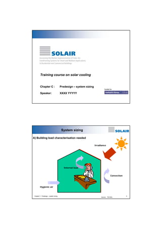
  • 1. funded by Chapter C : Predesign – system sizing Speaker: XXXX YYYYY Training course on solar cooling Chapter C : Predesign – system sizing 2 System sizing Convection Hygienic air Internal load Irradiance Source : TECSOL A) Building load characterisation needed
  • 2. Chapter C : Predesign – system sizing 3 System sizing Internal loads Chapter C : Predesign – system sizing 4 System sizing
  • 3. Chapter C : Predesign – system sizing 5 Solar collectors and thermally driven cooling desiccant adsorpti on 1-effect absorpti on 2-effect absorpti on SAC = solar air coll. CPC = stationary CPC FPC = selectively coated flat plate EHP = evacuated heat-pipe EDF = evacuated, direct flow SYC = stationary concentrated, Sydney-type SAC = solar air coll. CPC = stationary CPC FPC = selectively coated flat plate EHP = evacuated heat-pipe EDF = evacuated, direct flow SYC = stationary concentrated, Sydney-type 0.0 0.1 0.2 0.3 0.4 0.5 0.6 0.7 0.8 0.9 1.0 0.00 0.05 0.10 0.15 0.20 0.25 0.30 0.35 ∆T/G [Km 2 /W] ηcoll SYC EDF FPC SAC EHP CPC Source : Fraunhofer ISE A) Choice of technologies Chapter C : Predesign – system sizing 6 Solar production 0 25 50 75 100 125 150 175 0,0 0,1 0,2 0,3 0,4 0,5 0,6 0,7 0,8 0,9 flat-plate evac. tube evac. flat-plate CPC-collector parabolic trough Irradiation: 800 W/m² direct normal 200 W/m² diffuse efficiency T - TAMB [K] 60 80 100 120 140 160 180 200 0 100 200 300 400 500 600 700 800 900 1000 Barcelona energyyield[kWh/m²] temperature [°C] FPC EFPC ETC CPC PTC 60 80 100 120 140 160 180 200 0 100 200 300 400 500 600 700 800 900 1000 Huelva energyyield[kWh/m²] temperature [°C] FPC EFPC ETC CPC PTC FPC: flate plate collector EFPC: flate plate collector with concentrating parabolic compound (CPC) ETC: vaccum tube collectors CPC: vaccum tube collectors with concentrating parabolic compound (CPC) PTC: parabolic trough collector Source : Aiguasol
  • 4. Chapter C : Predesign – system sizing 7 ProducedCold rFactoConversion ConsumedEnergyalConvencion PEspec = conveleccold elec eleccoldelec elec cold elec elec conv,spec COP 1 Q Q1 Q 1Q Q Q PE εεε ε ==== Specific Primary Energy (PE) (KWh PE/KWh cold): Conversion factor: Electricity – 0.36; Fossil Fuel – 0.9 Conventional Compression Chiller: Source : INETI Primary energy analysis Definitions Chapter C : Predesign – system sizing 8 towercooling,spec thermalfossil sol towercooling,spec cold heatdriving fossil sol towercooling,spec coldfossil solheatdriving towercooling,spec coldfossil backup towercooling,spec cold fossil backup solar,spec PE COP. )F-(1 PE Q Q)F-(1 PE Q 1)F-(1Q PE Q 1Q PE Q Q PE += += += += += ε ε ε ε ε heatdriving cold thermal Q Q COP =       += + = == thermalelect ercoolingtowspec, cold coldtdrivinghea elect ercoolingtowspec, coldelect edheatrejectercoolingtowspec, cold elect ercoolingtow ercoolingtow,spec COP 1 1 E Q )QQ(E Q 1QE Q E PE ε ε ε ε Solar Thermal Driven Chiller: With: Cooling tower: Source : INETI Primary energy analysis Definitions
  • 5. Chapter C : Predesign – system sizing 9 0.0 0.5 1.0 1.5 2.0 2.5 0 0.1 0.2 0.3 0.4 0.5 0.6 0.7 0.8 0.9 1 Solar Fraction for cooling PEspec,sol,kWhPE/kWhcold COP = 0.6 COP = 0.8 COP = 1.0 COP = 1.2 Conv 2 Conv, 1 Primary energy analysis COPconv = 2.5 COPconv = 4.5 heat source: solar collector + fossil fueled backup primary energy conversion factor for electricity: 0.36 primary energy conversion factor for fossil fuels: 0.9 heat source: solar collector + fossil fueled backup primary energy conversion factor for electricity: 0.36 primary energy conversion factor for fossil fuels: 0.9 Source : Fraunhofer ISE Chapter C : Predesign – system sizing 10 Comparison between absortion and compression Efficiency based on primary energy 0 0.1 0.2 0.3 0.4 0.5 0.6 0.7 0.8 0.9 1 solar fraction cooling 0 0.5 1 1.5 2 specific primary energy per unit of cold conventional system thermal system, low COP thermal system, high COP no primary energy saving saves primary energy Source : Aiguasol
  • 6. Chapter C : Predesign – system sizing 11 ! High solar fraction for cooling necessary for solar thermally driven cooling equipment with low COP which use a fossil fueled backup ! A lower solar fraction is acceptable if thermally driven cooling equipment with a higher COP is employed ! An alternative is to use a conventional chiller as a backup (e.g. in case of a large overall cooling power) ! Primary energy savings are always achieved using a solar thermally autonomous systems but no guarantee for strictly keeping desired indoor comfort limits can be given ! In any case the use of the solar collector should be maximised by supplying heat also to other loads such as the heating system or hot water production Consequences of primary energy performance Chapter C : Predesign – system sizing 12 Design Design with regard to solar-assisted air-conditioning mainly means ! Selection of the proper thermally driven cooling equipment for the selected air-conditioning system ! Selection of the proper type of solar collectors for the selected air- conditioning system and thermally driven cooling equipment ! Sizing of the solar collector field and other components of the solar system with regard to energy and cost performance
  • 7. Chapter C : Predesign – system sizing 13 Design approaches ‚Rules of thumb‘ Collector cost per heating capacity Cost of solar heat for given climate Load - gain - analysis for given climate and load Anual cost based on load- gain-analysis Computer design tool with predefined systems Open simulation platform Accuracy,reliabilityofresults,detailsofdesigninformation Requiredsysteminformation,effortforparametrization Source : Fraunhofer ISE Chapter C : Predesign – system sizing 14 Design point design design,cold design,collcollcoll COP P GA =η⋅⋅ == > designdesign,collcoll spec COPG 1 A ⋅η⋅ = Example Gcoll = 800 W/m2 hcoll,design = 0.5 COPdesign = 0.7 ==> Aspec = 3.57 m2 per kW cooling power Source : Fraunhofer ISE
  • 8. Chapter C : Predesign – system sizing 15 + Method allows a very quick assessment (guess) about the required collector area, if the efficiency of the collector and the COP of the thermally driven cooling equipment is known – Method neglects completely the influence of the variation of radiation on the collector during day and year – Any information on the specific site and load is neglected – Method neglects completely part load conditions of cooling load in thermally driven cooling equipment Advantages and disadvantages Chapter C : Predesign – system sizing 16 Sizing Source : EAW Average values of the specific collector area " for Absorption- and Adsorption chillers 3,0 to 3,5 m²/kW chilling capacity " for open technologies (DEC, liquid DEC): 8 to 10 m² per 1.000 m³/h rated air flowrate
  • 9. Chapter C : Predesign – system sizing 17 Collector first cost ⊥⊥ − ⋅− − ⋅−⋅Θ=η G )TT( c G )TT( cc)(k 2 ambav 2 ambav 10 ⊥⊥ ⊥ ⋅η =⇒ ⋅η =⇒⋅η⋅= G kW1 A G Q AGAQ spec use use & & specspecpower,heat CostACost ⋅= incident angle modifier optical efficiency linear heat loss coeff. quadr. heat loss coeff. average fluid temperature ambient air temperature radiation on collector specific collector cost Source : Fraunhofer ISE average fluid temperature = operating hot temperature of cooling system Chapter C : Predesign – system sizing 18 Collector cost versus specific required area 0 400 800 1200 1600 2000 1 2 3 4 5 6 required absorber area [m2 /kW] collectorfirstcost[€/kW] evacuated tube flat plate flat plate - integrated roof stationary CPC Tav = 75°C Gcoll = 800 W/m2 Source : Fraunhofer ISE
  • 10. Chapter C : Predesign – system sizing 19 Advantages and disadvantages + Method allows a rough comparison of different solar collectors, if the collector parameters and the operation temperature of the thermally driven cooling equipment are known – Method neglects completely the influence of the variation of radiation on the collector during day and year – Any information on the specific site and load is neglected – Method neglects completely part load of cooling load and thermally driven cooling equipment Chapter C : Predesign – system sizing 20 Solar heat cost annuityspecannual fCostCost ⋅= gross annual heat Q Cost Cost = annual collector cost spedific collector cost (€/m2 ) annuity factor solar heat cost (€/kWh of heat) collector gross heat production .dataicallogmeteoroatingmindotheofvalueshourlygsinucalculatedTypically .etemperaturoperationgivenaandsitegivenaatproductionheatcollectorannualQgross = Source : Fraunhofer ISE
  • 11. Chapter C : Predesign – system sizing 21 Solar heat cost 0 4 8 12 16 20 0 200 400 600 800 1000 1200 1400 annual gross heat production [kWh/m2 ] heatcost[€-cent/kWh] etc fpc irc cpc Palermo, Tav = 75°C Source : Fraunhofer ISE Chapter C : Predesign – system sizing 22 Solar heat cost 0 4 8 12 16 20 0 200 400 600 800 1000 1200 1400 annual gross heat production [kWh/m2 ] heatcost[€-cent/kWh] etc fpc irc cpc Palermo, Tav = 95°C Source : Fraunhofer ISE
  • 12. Chapter C : Predesign – system sizing 23 Simple software tool SHC (NEGST project) Only needs monthly cooling (heating) load Free download in: http://www.swt-technologie.de/html/publicdeliverables3.html Compares monthly loads (heating and coling) with monthly solar energy gains. It is based on PHIBARFCHART Method - The results are primary energy savings for colector area installed. Chapter C : Predesign – system sizing 24 Advantages and disadvantages + Method allows a good comparison of different solar collectors using their parameters and the radiation data of a specific site + The maximum possible heat production of a specific solar collector for a given site (annual meteorological data file) and a given constant operation temperature is determined – Any information about the load profile is neglected – Method neglects completely part load of cooling load and thermally driven cooling equipment
  • 13. Chapter C : Predesign – system sizing 25 meteo data building model collector model solar fractions for heating and cooling COP, ε heatload solar gains 0 50 100 150 200 250 0 100 200 300 400 500 600 700 800 heating cooling 1 0.5 0.25 0.1 ! For each hour of the year the required heat for cooling (heating) is computed, e.g. using building simulation ! Global efficiency factors for transformation of heat in cooling (heating) are used to describe the technical equipment ! Calculation of hourly collector gains using different operation temperatures for cooling and heating Correlation of loads and gains Source : Fraunhofer ISE Chapter C : Predesign – system sizing 26 Software tools needed to determine hourly cooling (heating) loads of a building TRNSYS – Commercially available (www.sel.me.wisc.edu/trnsys/) Energy plus – Download free (www.eere.energy.gov/buildings/energyplus/ ) ESP-r – Download free (http://www.esru.strath.ac.uk/Programs/ESP-r.htm ) A list of other software tools can be found : (http://www.eere.energy.gov/buildings/tools_directory/)
  • 14. Chapter C : Predesign – system sizing 27 Simple software tools using hourly cooling (heating) load SACE Cooling evaluation light tool – available in http://www.solair-project.eu/218.0.html Results using this software tool while be shown latter Chapter C : Predesign – system sizing 28 Simple software tools using hourly cooling (heating) load SolAC – available in: http://www.iea-shc-task25.org/english/hps6/index.html Four different units are considered in this software: • Solar system • Cooling device • Air handling unit • Cooling and heating components in the room The input data for the programme is: • weather data including solar radiation (hourly data) • load files including heating and cooling loads (hourly data)
  • 15. Chapter C : Predesign – system sizing 29 Dynamic simulation software tools using hourly cooling (heating) load - System orientated TNSYS - www.sel.me.wisc.edu/trnsys/ ColSim - www.colsim.de Insel - http://www.inseldi.com/index.php?id=21&L=1 - Building Orientated Energy plus - www.eere.energy.gov/buildings/energyplus/ Software Solar Components AC Components New Components Free downlaod Open source code TRNSYS Yes Yes Yes No Yes ColSim Yes Yes, but no clear list was possible to obtain. Yes Not clear Yes Energy Plus Yes Yes Yes Yes Not clear INSEL Yes Yes Yes NO NO Chapter C : Predesign – system sizing 30 Identification of HVAC components available which are most interesting for CTSS TRNSYS 16. Type 107 – Absorption Chiller (hot water fired, single effect) Type 51 – Cooling Towers. TESS Libraries Type 680 – Single-effect hot water-fired absorption chiller (Equivalent to type 107 of TRNSYS 16) Type 679 – Single-effect steam-fired absorption chiller Type 677 – Double-effect hot water-fired absorption chiller Type 676 – Double-effect steam-fired absorption chiller Type 683 – Rotary desiccant dehumidifier – models a rotary dessicant dehumidifier containing nominal silica gel.
  • 16. Chapter C : Predesign – system sizing 31 solar gas elect caldera bomba calor absorció calefacció refrigeració solar gas elect caldera bomba calor absorció calefacció refrigeració Source : Aiguasol Calculation methods : Estimated calculation with energy balances Solar thermal energy availability • Simulation tool for the solar systems • “Infinite” consumption with high return temperature (chilled water) • 100% use of produced solar energy Energy load determination, per year and per month: cold, heat, and DHW • Calculation tool for the building energy load • DHW energy load determination Use factor determination • Depends on the relation availability / load • Depends on the heat storage Definition of energy flows between subsystems • -> Definition of a control strategy Chapter C : Predesign – system sizing 32Source : Fraunhofer ISE
  • 17. Chapter C : Predesign – system sizing 33 Guidelines for design, control & operation of solar assisted adsorption chillers 0 0.1 0.2 0.3 0.4 0.5 0.6 0.7 60 65 70 75 80 85 90 95 temperature, °C COP,COPsol,etacoll 20 30 40 50 60 70 80 90 coolingpower,kW etacoll COP COPsol cooling power COPsol = COP * ηcoll Radiation on collector: 800 W/m 2 COPsol = COP * ηcoll Radiation on collector: 800 W/m 2 COP-maximum at about 70°C Source : Fraunhofer ISE Chapter C : Predesign – system sizing 34 Efficiency of solar thermal cooling systems 0.00 0.10 0.20 0.30 0.40 0.50 0.60 60 80 100 120 140 160 180 200 Working temperature [°C] COPsolar 500 600 700 800 900 1000 Irradiation W/m2 ==> optimal working temperature depends on the irradiation level Source : Fraunhofer ISE
  • 18. Chapter C : Predesign – system sizing 35 Evaluation parameter: Costs of saved primary energy ! Combined Energy-costs-Performance ! enables comparison of different system designs Costs of primary energy saved = ∆ Total annual costs ∆ Primary energy ∆primary energy = annual primary energy saving of the solar driven system compared to a conventional reference system ∆primary energy = annual primary energy saving of the solar driven system compared to a conventional reference system ∆total annual costs = annual supplementary costs of the solar driven system compared to a conventional reference system ∆total annual costs = annual supplementary costs of the solar driven system compared to a conventional reference system Source : Fraunhofer ISE Chapter C : Predesign – system sizing 36 10% 20% 30% 40% 50% 60% 55 65 75 85 95 105 115 125 135 Storage volume, l/m 2 Primaryenergysaved 160 180 200 220 240 260 280 ! Madrid ! Office buildings ! Flat plate collector ! Backup: Gas boiler ! Absorption chiller Collector surface, m2 Example: primary energy savings (in%ofthereferencesystem) Growing collector surface Source : Fraunhofer ISE
  • 19. Chapter C : Predesign – system sizing 37 140% 145% 150% 155% 160% 165% 170% 175% 180% 55 65 75 85 95 105 115 125 135 Speichervolumen, l/m2 Jahreskosten,%Referenz 160 180 200 220 240 260 280 Kollektorfläche, m2 ansteigende Kollektorfläche Example: annual costs ! Madrid ! Bürogebäude ! Flachkollektor ! Backup: Gaskessel ! Absorptions- kältemaschine ! Madrid ! Office buildings ! Flat plate collector ! Backup: Gas boiler ! Absorption chiller Growing collector surface Collector surface, m2 Storage volume l/m2 Annualcosts,%reference Source : Fraunhofer ISE Chapter C : Predesign – system sizing 38 0.12 0.14 0.16 0.18 0.2 0.22 0.24 0.26 0.28 55 65 75 85 95 105 115 125 135 Speichervolumen, l/m2 KosteneingespartePE,€/kWh 160 180 200 220 240 260 280 Kollektorfläche, m2 Minimu m Example: Costs of primary energy savings ! Madrid ! Bürogebäude ! Flachkollektor ! Backup: Gaskessel ! Absorptions- kältemaschine ! Madrid ! Office buildings ! Flat plate collector ! Backup: Gas boiler ! Absorption chiller Storage volume l/m2 Collector surface, m2 Costsofprimaryenergysaved,€/kWh Source : Fraunhofer ISE
  • 20. Chapter C : Predesign – system sizing 39 Dynamic modelling with TRNSYS… necessary System sizing Chapter C : Predesign – system sizing 40 Transient simulation – TRNSYS TRNSYS features – Numerical calculation methods – Continuous yearly simulation of the thermal behaviour of the installation, analysing the transitory phenomenon of the heat flows – Variability of climatology (temperature, irradiation) is taken into account – Enables analysis of the different factors which determine the energetic behaviour of the system # parametric study# optimisation
  • 21. Chapter C : Predesign – system sizing 41 TRNSYS Workspace Transient simulation – TRNSYS Chapter C : Predesign – system sizing 42 Results obtained with TRNSYS Transient simulation – TRNSYS
  • 22. Chapter C : Predesign – system sizing 43 Analysis of the results 0 5 10 15 20 25 30 35 1 14 27 40 53 66 79 92 105 118 131 144 157 Tamb Tair 0 1000 2000 3000 4000 5000 6000 7000 Gener Febrer Març Abril Maig Juny Juliol Agost Setembre Octubre NovembreDesembre kWh Monthly heating demand in kWh Total demand in kWh Solar contribution in kWh Transient simulation – TRNSYS Chapter C : Predesign – system sizing 44 Calculation options with dynamic simulation tools Separated calculation of building and cooling system – Step 1: Simulation of the building demand (heating, cooling) – Cooling system model= ideal system with infinite power. – Intermediate result: hourly data of heating and cooling demand. – Step 2: Simulation of the cooling system – Result: energy contribution of the real cooling system Coupled calculation of the building and the cooling system – Simulation of the building (demand) and of the cooling system in the same software – Cooling system model = real system – Results: • Energy contribution of the real cooling system • Degree of fulfilment of the comfort criteria Transient simulation – TRNSYS
  • 23. Chapter C : Predesign – system sizing 45 Which questions have to be answered? 1. Which is the basic sizing of the main equipments? • Collector field : type and size in m2 • Absorption machine: kWf 2. What is the solar contribution to the cooling, heating and global demand? 3. Which is the basic sizing of the back-up system? • type (boiler, heat pump, air conditioner...); • size kW 4. Which are the energy savings? 5. What are the additional costs compared to a conventional installation? 6. What is the pay-back time? Chapter C : Predesign – system sizing 46
  • 24. Chapter C : Predesign – system sizing 47 Sizing of the absorption machine f f solar gensolar gen f kW m m kW kW kW m kW kW kW 2 22 332.015.065.0 ==×× Demand peak < maximal total power (absorption + auxiliaries) + cold storage Operating with solar energy: minimal power required to absorb the solar heat produced and convert it into cold. # 3 m2/kWf – Criteria 1: the absorption machine is able to use the maximal solar production. Solar peak production approx. 0.5 kW/m2 (1000 W/m² x 50 % efficiency) – Criteria 2: the solar energy produced during the day of maximal irradiation can be totally used by the absorption machine, assuming that the required heat storage is available – Maximal power to guarantee a minimal solar contribution (typically > 60...70 %) and/or an reasonable number of operating hours (> 1000 h/year). Rules of Thumb – pre-design rules of solar cooling systems Chapter C : Predesign – system sizing 48 Sizing of the heat/cold storage Cold storage – Cover demand peaks (smaller machines, larger number of operating hours) – Avoid part-load or intermittent operation Heat storage – Gap between cooling demand and solar heat availability – Guarantee continuous operation of the machine during days of intermittent irradiation – Typical size: 25 .. 50 litres / m2 of collector Rules of Thumb – pre-design rules of solar cooling systems
  • 25. Chapter C : Predesign – system sizing 49 Control strategy Starting priority (cold production) according to the energy efficiency – Cold production with heat-pump in case of simultaneous heat demand. Solar contribution for space heating. – Cold production with absorption through solar heat – Cold production with heat-pump (without heat recovery) – Cold production with absorption through gas boiler Rules of Thumb – pre-design rules of solar cooling systems Chapter C : Predesign – system sizing 50 System sizing 75 – 95°C 75 – 95°C 25 - 35°C 7 – 12 °C 700W/m² 85 kW 77 kW 50 kWf 127 kW 200 m² Source : TECSOL
  • 26. Chapter C : Predesign – system sizing 51 System sizing ! 1 Cooling load : 50 kWc ! 2 Inlet generator : 50 / 0.65 = 77 kW ! 3 Cooling tower : 77 + 50 = 127 kW ! 4 Primary loop efficiency : 0.9 ! 5 Heat load on collector side : 85 kW ! 6 Average irradiance : 700 W/m² ! 7 Collector efficiency : 0.6 ! 8 Collector area : 85/0.7/0.6 = 200 m² ! 9 Optimal tilt : 30° (France South) ! 10 Groung space necessary > 300 m² Chapter C : Predesign – system sizing 52 Check list concept : example 233 Possible undersizement of solar system thanks to back up 333Passives actions decrease potential 223Yearly heating and DHW needs 223Yearly adequation production <-> load 133Daily adequation production <-> load Load TECHNICAL FEASIBILITY 333Adapted existing material (or planned) for back up 233Adapted distribution network 123Space for technical premices 223Important area for solar collection 333Climate Building HotelPublic buildingIndustry Source : TECSOL
  • 27. Chapter C : Predesign – system sizing 53 455558 TOTAL SCORE (on 63) : 232Presence of a long term financed monitoringMonitoring 223Regulat operation action possibilitiesFEASIBILITY 223Skilled internal technical staff O&M ORGANISAT. 133Financial stability of building owner 231National & international supports eligibility 333Environmental action politics 323Importance in term of marketing impactFEASIBILITY 333Building owner motivationECONOMICAL 133High investment capacity Building owner 223Low water cost 331High cost of saved energy Cost of energy HotelPublic buildingIndustry Check list concept : example Source : TECSOL Chapter C : Predesign – system sizing 54 Disclaimer This training has been developed in the context of SOLAIR. SOLAIR is a European co- operation project for increasing the market implementation of solar-air-conditioning systems for small and medium applications in residential and commercial buildings. For further information on the project or on products of the project see: www.solair- project.eu The project SOLAIR is supported by the Intelligent Energy – Europe (IEE) programme of the European Union promoting energy efficiency and renewables. More details on the IEE programme can be found on: http://ec.europa.eu/energy/intelligent/index_en.html The sole responsibility for the content of this training lies with the authors. It does not represent the opinion of the European Communities. The European Commission is not responsible for any use that may be made of the information contained therein.
  • 28. Note – This presentation is not owned by RE-Docs. It has simply been shared for wider dissemination because of its useful content. The author have been clearly acknowledged on www.redocs.co In case of any issues you may contacts us at www.redocs.co/contact Visit us on www.redocs.co your personal library on RE Hope you found the presentation useful! for similar useful material