Giant magnetoresistance and their applications

Giant magnetoresistance (GMR) is a quantum mechanical magnetoresistance effect observed in multilayers composed of alternating ferromagnetic and non-magnetic conductive layers. The 2007 Nobel Prize in Physics was awarded to Albert Fert and Peter Grünberg for the discovery of GMR. The effect is observed as a significant change in the electrical resistance depending on whether the magnetization of adjacent ferromagnetic layers are in a parallel or an antiparallel alignment. The overall resistance is relatively low for parallel alignment and relatively high for antiparallel alignment. The magnetization direction can be controlled, for example, by applying an external magnetic field. The effect is based on the dependence of electron scattering on the spin orientation.

Empfohlen
Weitere ähnliche Inhalte
Was ist angesagt?
Was ist angesagt? (20)
Ähnlich wie Giant magnetoresistance and their applications
Ähnlich wie Giant magnetoresistance and their applications (20)
Mehr von Premashis Kumar
Mehr von Premashis Kumar (12)
Kürzlich hochgeladen
Kürzlich hochgeladen (20)
Giant magnetoresistance and their applications
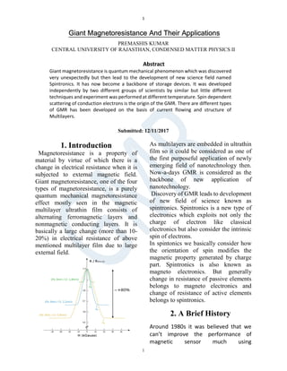
- 1. 1 1 Giant Magnetoresistance And Their Applications PREMASHIS KUMAR CENTRAL UNIVERSITY OF RAJASTHAN, CONDENSED MATTER PHYSICS II Submitted: 12/11/2017 1. Introduction Magnetoresistance is a property of material by virtue of which there is a change in electrical resistance when it is subjected to external magnetic field. Giant magnetoresistance, one of the four types of magnetoresistance, is a purely quantum mechanical magnetoresistance effect mostly seen in the magnetic multilayer ultrathin film consists of alternating ferromagnetic layers and nonmagnetic conducting layers. It is basically a large change (more than 10- 20%) in electrical resistance of above mentioned multilayer film due to large external field. As multilayers are embedded in ultrathin film so it could be considered as one of the first purposeful application of newly emerging field of nanotechnology then. Now-a-days GMR is considered as the backbone of new application of nanotechnology. Discovery of GMR leads to development of new field of science known as spintronics. Spintronics is a new type of electronics which exploits not only the charge of electron like classical electronics but also consider the intrinsic spin of electrons. In spintonics we basically consider how the orientation of spin modifies the magnetic property generated by charge part. Spintronics is also known as magneto electronics. But generally change in resistance of passive elements belongs to magneto electronics and change of resistance of active elements belongs to spintronics. 2. A Brief History Around 1980s it was believed that we can’t improve the performance of magnetic sensor much using Abstract Giant magnetoresistance is quantum mechanical phenomenon which was discovered very unexpectedly but then lead to the development of new science field named Spintronics. It has now become a backbone of storage devices. It was developed independently by two different groups of scientists by similar but little different techniques and experiment was performed at different temperature. Spin dependent scattering of conduction electrons is the origin of the GMR. There are different types of GMR has been developed on the basis of current flowing and structure of Multilayers.
- 2. A.Premashis Kumar GMR And its applications 2 magnetoresistance property. So discovery of GMR was completely unexpected. In 1986 by Brillouin scattering experiment Grunberg showed that two layers of Fe separated by nonmagnetic layer of Cr is actually coupled antiferromagnetically. In 1988 GMR was measured and identified independently by two different groups-Albert Fert and co. at University of Paris Sud,Orsay,France and Peter Grünberg and co. at Jülich,Germany. Stuart Parkin and his co-workers showed GMR in multilayer ultrathin film made by sputtering technique in 1990 by exploring a long range of thickness.In 1991 spin valve GMR, best way to obtain AF configuration between two ferromagnetic layers was invented. After five years of its discovery GMR sensors was first exploited commercially by IBM in 1994 for read out in hard disk drives. In 1995 TMR was rediscovered by scientists. Discovery of GMR and its practical importance has been recognised with the award of the 2007 Nobel physics prize to Albert Fert and Peter Grünberg. 3. Origin of GMR The phenomenon which is behind the origin of giant magnetoresistance is known as spin dependent quantum mechanical scattering. Spin is getting scattered from the interface between single domain ferromagnet and nonmagnetic ultrathin layer depending on relative orientation of electron’s spin and magnetic moment of spin. This situation is analogous to light passing through polarizer in optics. Density of state is defined as number of states present between energy E and E+dE . In the ground state Fermi level is highest occupied energy state. For nonmagnetic material number of spin up and spin down electrons are equal so if we represent this by band structure then both spin up and spin down electron energy band will be equal. But in the case of magnetic materials like Fe or Co, as there is different number of spin up and spin down electrons so there is a splitting in energy band of spin up and spin down electrons. If any case we consider that spin up electron is majority spin and spin down electrons as minority FIGURE 1: ENERGY BAND IN THE CASE OF NON MAGNETIC MATERIAL FIGURE 2: SPLITTING OF LEVEL IN THE CASE OF FERROMAGNETIC MATERIAL spin then spin up bands will be filled up to the maximum energy level. So Fermi energy in the case of ferromagnet is different for two different spin orientation.
- 3. A.Premashis Kumar GMR And its applications 3 Electrical resistance is generated because of scattering of conduction electron in material. In a simplest multilayer system If we consider spin ordering in both ferromagnetic layers are same which is spin up, then when a conducting electron with spin up orientation tries to go from one layer to another layer it will not be scattered as it has same spin orientation. But if the spin orientation of conducting electron is down then it will be scattered by two up spin in the ferromagnetic layers because of relatively opposite spin orientation. Because of this spin dependent scattering spin up conduction will go through easily as it is freeway for it but spin down electron will be slows down. 4. Resistive Model of Spin dependent Conduction Spin dependent of scattering and conductivity during the passing of conducting electron through the ferromagnetic material was first suggested by Mott around 1936 and it was demonstrated experimentally by Fert and co. around 1968. If we consider two antiparallel orientation of spin in the two ferromagnetic layers then as a first approximation we can consider this two layers create two independent channels for transport of conducting electrons. Now if we dope the magnetic material with selected impurity then depending upon resonant scattering on impurity level there will be different resistivity at different channel. Experiments by Fert using series of Fe and Ni alloys shows different results. We can translate the experimental results by ‘resistivity model’ or ‘Two current model’. In this two current or resistivity model electrical resistivity of ferromagnetic conductor is simply given by: In the above case we neglect the spin mixing resistivity term as in the case of low temperature spin flip scattering is too small. Spin asymmetry coefficient of two channel is given by: ↓ ↑ Relation between this and another coefficient is given by following equation: Resistivity is linearly proportional to the effective mass and inversely proportional to number of states n, relaxation time and number of states ↑ ↓ ↑ ↓ Where ↑ is resistivity of spin up channel Where ↓ is resistivity of spin down channel
- 4. A.Premashis Kumar GMR And its applications 4 near Fermi level. So we can say that spin dependence of the above mentioned factor namely effective mass, relaxation time, number of states is actually the reason of spin dependency of resistivity of ferromagnet. If in the case of Ni ferromagnetic layers we use Co as impurity then experiments shows that resistivity of spin down channel is 20 times larger than spin up channel. As doping creates a blocking down condition in spin down channel and there is shunting by spin up channel. Quantum mechanically we can say that resonant scattering on impurity level there is a pick in spin down channel which is the origin of this kind of blocking down condition. On the other hand if we use we use 1% V as doping element then it results in completely opposite situation. Resistivity of spin down channel is very low now. Now if we add both Co and V impurities at the same time then there will be blocking down condition in both channels of Ferromagnets due to which conduction electrons will be significantly slowed down in both channels. So the resistance of the alloy will be very large. Whereas if we use Co and Fe as two impurities then conduction in spin down channel will be stopped but conduction electron moves freely through spin up channel. That’s why resistivity of alloy is so small. This is the basic idea that leads to find out the phenomenon called Giant magnetoresistance. 5. Theoretical Model The physical model of GMR was developed on the basis of above discussed model of ferromagnetic material. The idea was instead of using impurities if one puts a nonmagnetic ultrathin layer of the order of nm on the way of conduction electron passing through one layer of ferromagnet to another layer of ferromagnet. We consider that in the case of simplest possible multilayer if spin up and spin down electron scattered differently when passing through magnetic layers. Now if we take two ferromagnetic materials such that they have spin magnetic moment in the same direction i.e ferromagnetic orientation then when conduction electron is passing through the channel then one of the spin direction is slowing down by magnetic layers but for opposite spin orientation of conduction electron there will be always a shunting condition and it will be subjected to very small scattering. That is why electrical resistance is very low in the case of ferromagnetic orientation of the magnetic layers. But if we take two layers such that they have antiparallel spin magnetic moment then one channel will strongly slows down the majority spin orientation of conduction electrons and other channel will block the minority spin direction of conduction electron.So both spin direction is strongly scattered due to effect of both layers oriented like
- 5. A.Premashis Kumar GMR And its applications 5 antiferromagnet. This results in high electrical resistance in the case of AF orientation of two magnetic material. This theoretical model given by Albert Fert & co. can explain the phenomenon properly only if the thickness(t) of ultrathin nonmagnetic layer << the mean free path( of conduction electrons. This is the reason behind selecting nonmagnetic layer of the order of nm. In the case of ferromagnetic orientation we can visualize a basic electronic circuit consists of two small resistances r in one branch and two large resistances R in other branch. So effective resistance of the whole circuit is given by So the resistance is dominated by shunt. On the other hand, we can visualise the antiparallel orientation of magnetic layers as a basic electronic circuit which have r and R resistance in each of the two branches. So effective resistance of the circuit is given by So as we can see .So finally the GMR ratio is given as In the case of parallel orientation electron of one layer can’t see what is going on the other magnetic layer as the magnetic resistance decreases exponentially. In more complicated and realistic model We need to consider wave function and intrinsic and extrinsic potential in which strong scattering will be visualised as spike in potential field. 6. Effect Of External Magnetic Field We will now see how the above mention GMR ratio changes in the presence and absence of large magnetic field. Let us consider in ferromagnetic the absence of field if the layers are arranged in AF orientation. Due to antiferromagnetic coupling it should have high magnetoresistance ratio. But by applying a strong magnetic field we can align all the spin magnetic moment in certain arbitrary direction. As now all the spin moment is in the same direction so it is similar to ferromagnetic orientation. In the case of this orientation as spin have same direction so current can easily tunnel through the layers and as a consequence of this electrical resistance is very low. So by using magnetic field we can induce a large change in electrical resistance. The large change in the resistance is given by ⁄ ∗ ≫ = =
- 6. A.Premashis Kumar GMR And its applications 6 Which is the amplitude of GMR. So in experiments there is as large as 80% variation of resistance have been observed between AF and ferromagnetic configuration with ultrathin spacer of 0.9 nm. GMR amplitude is decreased very rapidly with increase in the thickness of the spacer as the exchange coupling between two magnetic layers become very weak. If we consider initially multilayer of the Ferromagnetic orientation then there will be no effect of applied magnetic field. 7. GMR Spin Valves During the application of external applied field we can’t allow slow saturation of GMR amplitude which is common in general case. As in digital application where GMR will be exploited for 0 and 1 bit reading , it is required that GMR amplitude reaches the saturation point very sharply. Then it will be very sensitive to small field change. To fulfil this requirement GMR spin valve was developed. The first layer of spin valve is free magnetic layer which acts as valve. We can change the magnetic moment of this free magnetic layer using a small magnetic field. After that top layer there is an antiferromagnetic layer followed by a multilayer composed of two ferromagnetic (Co) layers with a nonmagnetic layer known as spacer. Magnetic moment of upper (Co) layer is broken or pinned by the antiferromagnetic layer above this because of exchange bias. As the net magnetization of the upper layer of Co is zero so we can only switch the second Co level. By applying external magnetic field we can rotate the top free layer in either directions by which we can have antiparallel configuration with high resistivity or we can have parallel configuration of very low resistivity. Hysteresis curve in this case is aligned more vertically than the normal case. GMR amplitude of GMR spin valve can vary up to 5% even for a very small magnetic field like 10 Oe. Such a huge spin magnetic moment sensitivity is very important for application of GMR in Digital field. 8. CPP GMR: Till now we only consider those CIP GMR with current flowing along the intermediate layers of multilayers element. Whereas in the case of CPP GMR current is flowing perpendicular to the surfaces. Although this phenomenon is hard to realise but it is very interesting one.
- 7. A.Premashis Kumar GMR And its applications 7 Experimental procedure of this is difficult one as we now need to measure resistance of a multilayer having very small geometrical factor and first experiment of CPP GMR was conducted at Michigan State University. CPP GMR works properly if thickness of ultrathin intermediate layer is smaller than the spin diffusion length. Spin accumulation effect at the interface of nonmagnetic and magnetic layers leads to occurence of GMR in CPP GMR. 9. Granular GMR Stuart Parkin and his two co-workers reproduced the result of Fert and Grunberg at IBM’s Algmaden research centre ,San Jose by not using the slow and precise expensive technique but they rather exploited faster but not so precise technique of sputtering. Co and Cu are immiscible elements so if we try to add Co to Cu, then Co will form a cluster like structure over the Cu matrix. In this case depending on the cluster size of Cu resistance in this type of material varies. So in this case there is no need of multilayer or continuous layer. So nanoparticle of Co embedded in Cu matrix is considered as an excellent candidate to generate GMR because of spin dependent scattering from interface of this two elements. 10. Applications 1. By applying GMR magnetic sensors were developed initially. 2. More difficult applications of GMR was found eight years later. Multilayers that produces GMR has been used in read head of hard disks .It is very difficult to detect very small magnetic field of bits but by using GMR is possible to measure this small bit magnetic field easily. It is possible to make disk of coin size using multilayers which is used in ipod classic. 3. Using the similar principle of magnetic storage devices, magnetonano ‘blood scanner’ has been developed to detect blood cancer. In this scanner nanoparticle is used to ‘tag’ antigen of cancer and after that this is read out by using Magnetic sensor. Acknowledgements: I would like to thank our course instructor DR.AJIT KUMAR PATRA. References [1]Chang, Liu; Wang,Min ;Liu, Lei ; Xiao, Pan; “A brief introduction to giant magnetoresistance”
- 8. A.Premashis Kumar GMR And its applications 8 [2]"The Nobel Prize in Physics 2007". NobelPrize.org. [3] Fert, Albert –“Giant Magnetoresistance” [4] How GMR Works [5]Giant Magnetoresistance [6]This itsy-bitsy phenomenon makes your iPod and hard drive tick. [7]Matthew,Melissa.“Giant Magnetoresistance” [8]Pratts,Andrew.“So what is Giant Magnetoresistance?” [9]Ennen,Inga;Kappe,Daniel;Thomas,Rem pel; Hütten,Andreas. “Giant Magnetoresistance: Basic Concepts, Microstructure, Magnetic Interactions and Applications” [10]GMR: A Giant Leap for IBM Research [11] Baibich, M.; Broto, J. ;Fert, A. ;Van, Dau;Petroff,F. “Giant Magnetoresistance of (001)Fel(001) Cr Magnetic Snperlattices” [12] Binasch, G.; Grunberg; Saurenbach; Zinn (1989). "Enhanced magnetoresistance in layered magnetic structures with antiferromagnetic interlayer exchange". Physical Review B. 39 (7)