
Empfohlen
Empfohlen
Weitere ähnliche Inhalte
Was ist angesagt?
Was ist angesagt? (20)
Andere mochten auch
Andere mochten auch (20)
Ähnlich wie Chapter 3
Ähnlich wie Chapter 3 (20)
Kürzlich hochgeladen
Kürzlich hochgeladen (20)
Chapter 3
- 1. Chapter 3 (b) pressing / rolling Metal Works, Casting Process and Heat Treatments for Steel - cold rolling - thread rolling 3.1 Cold Work (c) extrusion 1. Cold working of metals is permanent deformation of metals and - cold extrusion alloys below the temperature at which a strain-free microstructure - impact extrusion is produced continuously (recrystallization temperature). Usually in room temperature. 6. It is a finishing process in production to produce and function as : 2. Cold working causes a metal to be strain-hardened, deformed and i. to maintain accurate dimension of the product strengthened. ii. achieve clean and smooth finishing 3. When a sheet metal or ingot in cold work process, crystalline iii. achieve various of hardness degrees by applying various of structures (lattice) are changed, distort and stretched to the cold works direction of the worked. iv. repairing the machineability 3.1.1 Cold Rolling 1. Long lengths of metals sheet and plate with uniform cross sections can be produced. 2. The coils of metal are usually given a reheating treatment called annealing to soften the metal to remove internal stress introduced during the hot-rolling operation. 3. Smaller diameter roller will be operated to thinning the metal, and 4. The metal will be hardened and increased the strength for internal bigger roller used as support which will absorb vibration and strained causing the decreasing of ductility. Change its strength maintaining the thickness. and increase the electricity resistance. 4. Lubricating material usually applied to the work piece before and 5. These cold works usually applied after hot work process : after it is rolled to refine the surface and to prevent grain (a) drawing formation. - tube drawing 5. It is able to produce sheet metals as thin as 0.008mm – 0.009mm - wire drawing called foil.
- 2. 6. Advantages : 3.1.3 The Advantages And Disadvantages Of Cold Work i. surface free from oxidation 1. The advantages : ii. smoother and shinier surface i. good surface finishing because it smoother with no oxidation iii. fine fitting process iv. increase the tensile strength and toughness ii. exact measurement can be achieve with exact dimension control because of no dimension shrinkage 3.1.2 Wire and Tube Drawing iii. increase the machineability of the metal 1. Used to produce wire, rod and tube. iv. the product does not need any finishing works 2. A process in which wire stock is drawn through one or more v. good finishing properties tapered wire-drawing dies to the desired cross section. 3. Only annealed metal and with high ductilities metal can be 2. The disadvantages : processed. i. costing higher than hot work process 4. Friction, shear and tough pressure occurred at the joint part of the ii. the material become less in ductility caused by hardening work die and the work piece and will heatened the parts. iii. causing more brittle to the metal and lesser elasticity 5. Therefore, cooling elements are needed and dies has to be tough iv. cold work only can be use to the elastic metal and strong enough to resist wear and abrasive by those effects. v. bigger equipment and higher power usage 3.2 Hot Work 1. Hot working of metals is permanent deformation of metals and alloys above the temperature at which a strain-free microstructure is produced continuously (recrystallization temperature). 2. The recrystallization temperature for steel begins at 950°F - 1300°F. 3. If the temperature being work is sufficiently high, recrystallization takes place as quickly as the crystals become deformed and the metals can be heavily worked with ease without risk of cracking. 4. As the temperature falls during processing, recrystallization occurs more slowly, not only more force is required to achieve plastic
- 3. deformation, but there is an increased risk of surface cracks 3.2.2 Hot Rolling appearing. 1. Hot rolling is carried out to have greater reductions in thickness of 5. If the metal temperature is rising, become burnt, oxidation of the metal ingots, until certain thickness achieve, taken by rolling pass grain boundaries occurs and the material is severely weakened. when the metal is hot. 6. Main processes of hot work : 2. The ingots will go through two big cylinder roller and then other i. hot rolling rollers until achieve the needed thickness. ii. hot forging 3. Discontinuities in the ingots will be sealed or welded under huge iii. hot extrusion pressing process and gained a homogenous structure. iv. hot forming 4. Applications : railways, construction frames v. welding hot pressing 3.2.1 Hot Forging 1. The metal is hammered or pressed into a desired shape in the closed-die forging. 2. The usage of closed-die forging : i. The die cavity is the shape of finished component ii. Both part of dies attach to hammer and anvil iii. When force delivered, both parts combined and become one iv. To ensure full filling of the metal in the die, material quantities has to be more than the cavity 3.2.3 Hot Extrusion v. The surplus metal will run out through the die and forming the 1. The extrusion process is used to produce cylindrical bars or hollow flash tubes. 3. Applications : spanners, bolts, shafts 2. Extrusion is a plastic forming process in which a material under high pressure is reduced in cross-section by forcing it through an opening in a die. 3. The advantages : The ability to produce varies of complicated shape with accurate dimension and good finishing.
- 4. 4. Its produce continuously but only to metals with low melting point iii. accuracy in last dimension hard to achieve because of shrinkage and with good melting ability such as bronze, brass alloys and factor when the hot metal are cooling aluminium and its alloys. iv. life expectation for tools are lessen caused by working in higher temperature 3.3 Casting Process 1. Casting process is a production process where the metal is formed directly from the molten state, pouring it into a mould and allowing it to cool and solidify, expelled from the mould to be clean or machine for finishing. 2. The mould must be made from a material with a higher melting point than the molten metal which the casting is to be made. 3. The mould contains a cavity in the form of the finished product into which the molten metal is poured. 4. Types of casting process : 3.2.4 The Advantages and Disadvantages Of Hot Work a) sand casting 1. The advantages : b) lost wax/investment casting i. metal are in plasticity condition. Energy and needed forces are c) pressure-die casting small. Can be worked for bigger size metals d) shell casting ii. blow holes in ingots can be disappeared by compression e) centrifugal casting iii. suitable to almost all types of metal f) plaster of Paris casting iv. if finishing temperature are correct, smoother structure can be g) ceramic mould achieve h) evaporative pattern casting 2. The disadvantages : 3.3.1 The Purposes, Impotencies and Process of the Casting i. better surface cannot be achieve because of corrosion by 1. Stages of casting process : oxidation process in high temperature (a) metal is heated until its melted ii. higher in cost (b) pouring the molten metal in a cavity mould (c) leave the metal to solidify
- 5. (d) retrieved the solid metal from the mould out leaving the mould with a cavity where the molten metal are (e) clean or machine for finishing poured in to form a product. 2. The advantages : 4. To smoother the casting works and to ensure the mould cavity is (a) typical shapes of product which cannot be produce by other full with molten metal, a running system including building a process such as machining, forging and welding runner, a riser and a gate to the mould. (b) cast iron only can be worked through casting process because 5. A riser also provides surplus metal which can be drawn back of its properties and cannot be worked by other hot work to into the mould as shrinkage takes place during cooling and this form bars, rods or other shapes can avoids shrinkage cavities occurring in the casting. (c) project manufacturing are simplifies, the casting process able 6. The pattern has to be made oversize to allow for shrinkage of the to poured to complete shape of a product where other process, metal as it cools and it has called the shrinkage allowance. the product need to be heated or connected to form complete 7. A hollow casting can be made by using a core in the cavity. shape 8. Casting defects : (d) small amount of wasted materials compared to machining (a) scabs – these are blemishes on the surface of the casting process resulting from sand breaking away from the wall of the mould (e) casting is a cheaper process if compared to others cavity, due to lack of cohesiveness in the sand resulting from too (f) suitable for mass production : automotive industry products, low clay content or from inadequate ramming, too rapid pouring household products and agriculture machinery can also result in the scouring away the walls of the mould cavity (g) wasted metal can be recycle using casting process (b) cold shuts – result from casting intricate components with thin sections from metal which is lacking in fluidity or at too low 3.3.2 Sand Casting (Penuangan Pasir) temperature, sections of the mould may not fill completely or 1. The sand casting process is usually chosen for the production of the metal may flow too sluggishly and at too low temperature to small quantities of identical castings, complex castings with unite when separate streams meet intricate cores, large castings and structural castings. (c) hot tear – it is as same as part of the casting broken cause by 2. A mould made by compressing or ramming the casting sand coherent and strained by heat shrinkage attach to unsuitable (combination of silica sand and bantonite function as adhesive), mould design circling a pattern made by wood, forming a cavity in the mould. (d) blow holes – are smooth round holes with a shiny surface 3. The mould surrounded by a moulding box which separated into usually occur just below the surface of the casting, not normally 2 parts called cope and drag. Its helps in expelling the pattern visible until the casting is machined, caused by steam and gases being trapped in the mould. Results from inadequate venting,
- 6. incorrectly placed the risers, excessive moisture in the sand or iii. surface finishing quality are low and need to be machine excessive ramming reducing the permeability of the sand iv. the ira (grain) are not compacted, therefore low in (permeability is the ability of the sand to allow entrapped gases compactability and weak to escape between the individual sand particles) v. low in ductility (e) Other defects including porosity, uneven wall thickness, fins and vi. unsuitable for thinner casting product drawing. 11. Sand casting tools : 9. The casting sand should have these properties : i. SAND MOULD – containing 85% silica sand, 8% bentonite and (a) high heat temperature resistance 7% water (b) enough adhesive strength ii. MOULDING BOX/ FLASK – a box where use to made a mould (c) gases permeability in it, containing 2 parts (cope and drag), made by wood or metal (d) can be tested for grain size, compressive, tensile and shear iii. PATTERN – a model or replica of product, made according to strength, hardness and compactability the real shape of the product, made by wood, metal, plastic, wax 10. The advantages of sand casting process : or plaster i. manufacturing process for multiple usage iv. CORE – to produce a hollow product, made by plaster, metal, ii. suitable to produce one until thousand of casting units ceramic or silica sand iii. freedom in designing from weight, size and shape v. BELOS – to aired the sand grain in the mould or the cavity iv. can be use to produce component with the weight in vi. STRIP BAR – to strip or flatten the sand on the surface of the grammes until tones moulding box, made by steel v. bigger size product can be cast in hollow casting technique vii. LADLE – for mould finishing job as to fix broken mould, make a vi. typical shape can be make by using various of cores groove for molten metal stream, adding or reducing mould parts vii. can be use for all kind of metal including metal that cannot viii. GATE CUTTER & SQUIRE, MOULDING THROWEL – to fix be manufactured by other process such as cast iron small damage in the cavity and create a channel for molten viii. cost for making the mould are low because low in sand price metal flow and reusable ix. RAMMER – to compact or compress the sand casting while 11. The disadvantage of sand casting process : making the mould in the moulding box, made by wood or metal i. the cast exposed to crack while cooling if the design are not x. VENTILATION ROD – to create ventilation holes so the heat suitable and air contain in the mould can be departed ii. limited to small quantities production if the process done xi. POWDER BAG – fill with parting powder which will be manually scatter on the pattern before ramming the sand over
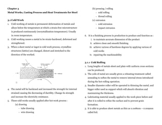
- 7. xii. SPRUE – to create a channel for getting system of the 12. Processing steps : molten metal (runner and riser) i) Step 1 : xiii. DRAW PIN – to draw out the pattern from sand mould the drag (lower moulding box) in upside down xiv. SKIMMING LADLE – to skim the slag/ impurities floating position and placed on top of a flat and clean plate in the molten metal in the furnace ensure the floor also flatted xv. DEGASING PLUNGER – to release the gas trapped in the molten metal xvi. SIEVER – to gain finer sand before ramming the sand Fig 1: Moulding box for sand mould casting ii) Step 2 : lower part of the split pattern placed in the drag the parting powder scattered over the pattern and the plate Figure above shows the process for preparing a mould for casting. For that, the type of pattern use is split pattern and also using a green sand core. Fig 2: Preparing the pattern for the sand ramming
- 8. iii) Step 3 : finer sand gain from sieving process place around and over the pattern for 3cm of thickness by pressing with the fingers, the finer sand then pressed to the pattern and around it compactedly ensure that the pattern are still while the sand compacted Fig 4: Adding and compressing the sand v) Step 5 : by using a strip bar, stripped/flatten the surface of the compressed sand the bar pulled from a conner to another by moving it to the right and left Fig 3: Pressing the finer sand around and over the pattern iv) Step 4 : then add the rest of the sand for ¾ into the moulding box use a rammer to compact the sand with slow stroke add more sand over the moulding box and compressed it with harder stroke Fig 5 : Stripped/ flatten the sand surface continue/ repeat this process until gaining compacted sand over the moulding box
- 9. vi) Step 6 : viii) Step 8 : flip the drag so that the pattern would be on top, sieve the sand in the moulding box to gain 3cm of then place the cope on top of the drag finer sand around and over the pattern lock both cope and drag together compress the sand with fingers add and ram the sand same as the fourth step Fig 6: The position of cope and drag vii) Step 7 : upper split pattern placed on top of the lower Fig 8: The sand mould after eighth step pattern in the drag perfectly, then placed the sprues (runner and riser) in the suitable positions shattered the parting powder over the pattern, ix) Step 9 : sprues and the sand surface in the drag use a strip bar to striped/flatten the surface of sand in the cope use a ladle to strip the sand surface around the sprues Fig 7: The position of the pattern and the sprues Fig 9: Strippen/flatten the sand mould using a strip bar
- 10. x) Step 10 : xii) Step 12 : twist the sprues, then pull it out slowly a channel for molten metal flow create using gate use a ventilation rod to make ventilation holes at cutter and squire the sand mould surface the channel should connect the sprue cavities and the mould cavity the channel function as a guide for the molten metal to flow to the mould cavity through sprue cavities Fig 10: Pulling out the sprue Fig 10: The ventilation rod usage xi) Step 11 : separate both boxes (cope and drag) and flip it to retrieve the split pattern Fig 12: Channels for molten metal flow before retrieve the pattern, knock it slowly so that the pattern and the sand surface are loosen xiii) Step 13 : use draw pins to retrieve both pattern sides from core will be place in the lower cavity mould then the the mould upper moulding box (cope) will be place back to its the cavity will formed after retrieving the pattern position (on top of drag) Fig 13: Core position in the moulding box Fig 11: The boxes part (cope and drag ) are separated to retrieve the pattern
- 11. xiv) Step 14 : 4. Casting metal : steel and alloys, aluminium, copper, magnesium, using moulding throwel, a basin for pouring the cobalt and nickel. molten metal into are made on the surface of the 5. The advantages : cope beside a sprue cavity called the runner i. an accurate measurement up to 0.005mm can be achieve the ready for pouring molten metal mould brought ii. smoother and no parting line appearance on the surface closer to the furnace iii. complicated shape can be cast the molten metal poured into the basin, flowing iv. no need for machining process through the runner and straight to the cavity 6. The disadvantages : after the molten metal solidify, the product can be i. highly in costing process, only for component that are retrieve by breaking the mould little in production and complicated shape which in need of accurate measurement ii. unsuitable for massive casting iii. problem occur when in need of core usage Fig 14: Pouring the molten metal into the mould process 3.4 Lost-wax/Investment Casting 1. In this process, molten metal are poured into a mould made by heat resistance material which made with wax. 2. The wax pattern then will be molten and flow out, leaving a ceramic mould, molten metal poured in the mould, filling the cavity. 3. Generally, it is used to produce small component with Products produce by lost-wax casting complicated shape and in need of highly accuracity such as sawing machine component, key, guns, etc.
- 12. 7. Steps in producing lost-wax casting: i) Step 1 : iii) Step 3 : lost-wax casting pattern made by wax the wax pattern then heated in a furnace between 100C to types of wax used for this process : paraffin, bee wax, acrawax 200C and resin (dammar). the wax will be melt and flow out or lost to form a cavity in the the wax pattern then dipped into concentrated material heat mould resistance coating to gain smoother surface for inside wall of the mould Fig 3: The wax melt and flow out or lost Fig 1: A wax pattern for lost-wax casting ii) Step 2 : iv) Step 4 : the wax pattern coated with heat resistance material then put the mould will be retrieved from the furnace and flipped into metal mould box or a flask upside down molten material are inserted into the mould box the molten metal will be poured into the cavity then, let it solidifies all over the box to form a mould when its solidify, the casting product can be retrieved the molten material consist of harden material and silica sand figure shows how a pattern posted in the mould and the molten material poured into the box Fig 2: The pattern positioned on the mould box
- 13. 3.5 Pressure Die Casting aluminium alloys and zinc to produce similar crystal structures 1. This process is for materials which has low melting with finer grains. temperature such as aluminium and zinc alloy but not for iron. 7. The mould is made by special steel and known as „die‟, tougher 2. This process operated by injecting molten metal into metal metal/ alloy with higher price and cost for making the mould are mould under the pressure. Molten metal or half melt metal are expensive. It is a permanent mould and can be use repeatedly. pushed in or injected into mould cavity with the pressure of 20 8. Advantages : economical and suitable for small component with to 2000 kg/cm2 and the pressure stays until the metal mass production. solidifies. 9. Complicated shape and thinner cross-section can be achieve 3. The type of mould used is permanent mould made by metal with this process, holes defect can be reduce because of there is and consists of two parts : fixed part and moveable part, the no air bubble trapped because it has been pressed out by mould also has air ventilations to expel the air trapped in the pressure. mould when the casting process occurs. 10. There is not need for runner and riser and it also lessen the 4. The casting machine divided into five parts/ mechanism : usage of material and production cost. i. for opening and shutting the mould mechanism 11. Applications : components for refrigerator, automotive, fans and ii. for pushing or injecting the metal into the mould washing machine. mechanism iii. for locking the mould until the metal solidifies mechanism iv. for insert and retrieve core automatically mechanism v. ejector pin for ejecting the cast product from the mould 5. There are two types of casting machine : hot chamber and cold chamber (a) the hot chamber machine : the melting metal furnace is part of Products made by pressure die casting the machine (b) the cold chamber machine : the melting metal furnace is not part of the machine, can be found in horizontal and vertical position 6. Because of the mould made by metal, higher cooling rate can be achieved compared to the sand mould. This help metals such as
- 14. 12. Casting metals : iii) Step 3 : (a) hot chamber process : zinc, tin (stanum), plumbum and alloy retrieving the core and output die retreat backward with low melting temperature (b) cold chamber process : aluminium, magnesium, brass alloy and non ferrous alloy with low melting temperature 13. Steps in making products for pressure die casting : i) Step 1 : molten metal inserted into the chamber iv) Step 4 : the ejector pin will eject the product out from die ii) Step 3 : a piston pushing/ injecting the molten metal into the die cavity
- 15. 14. The advantages : 3.5 The Advantages and Disadvantages Of Casting Process (a) in need of less working area compared to other casting processes Sand Pressure Lost-wax (b) the outputs are all similar Casting Die Casting (c) surface finishing highly achieve compared to other Casting processes Alloy/ metal that can be cast/ All Alloy All (d) products or components with complicated shape can be process based of produce Cu, Zn, Al (e) suitable for mass production because highly in Comparison of mechanical Medium Better Good production rate which upto 8000 casting per hour properties (f) job cost are low and the operator only need less Surface finishing Medium Better Better training Possibility of forming Good Better Better 15. The disadvantages : complicated shape (a) cost for mould and equipment are higher (b) the casting are limited (c) casting size are limited (d) limited only to metal or alloy which has low melting temperature (e) mould durability are lessen if the melting temperature for metal are higher (f) in need of expert workers for maintenance and mould supervise
- 16. 3.6 Heat Treatment for Steel 3.6.1 Purpose of Steel Heat Treatment Heat treatment is a sequence of heating and cooling designed 1. Increase strength and hardness to get the desired combination of properties in the steel. 2. Repairing the ductility The changes in the properties of steel after heat treatment are 3. Changing the grain size and chemical composition due to the phase transformations and structural changes that 4. Repairing the machine-ability occur during the heat treatment. 5. Stress relieving Heat treatment process : 6. Hardening 1. treatment for stable structure / soften the structure : 7. Changing the electricity and magnetic properties i) Annealing 1. Full Annealing ii) Normalizing 2. Stress Relieving Annealing 3.6.2 Recrystallization 3. Spheroidizing Annealing 2. treatment for unstable structure / harden the structure : i) Quenching ii) Tempering Recrystallization process (a) Before working (b) After cold working- the grain of the metal becomes distorted and internal stresses are introduced into the metal. (c) Nucleation commences at recrystallization temperature (d) Crystals commence to grow as atoms migrate from the original crystals and attach themselves to the nuclei (e) After annealing is complete the grain structure is restored
- 17. 3.6.3 Heat Treatment Process and Its Effects to Steel 3.6.4.2 Stress Relieving Annealing Material is heated Soaked to enough time It is a low temperature (about 500°C) annealing treatment Cooled to to certain (medium) and let the certain rate applied to cold worked steels. In practice, it is carried out temperature changing happen between 630°C and 700°C to speed up the process and limit 3.6.4 Annealing the grain growth. Annealing is heating the steel over the upper critical It results in lowering of the residual stresses, thereby lessening temperature and then cooling slowly through the the risk of distortion in machining. transformation range. This process only for steel with less than 0.4% carbon. Slow cooling is generally achieved in a closed furnace by The advantages of this process compared to full annealing: switching-off the supply. i. lessen fuel cost because the process only used low The purposes of annealling : temperature i. to reduce hardness ii. lessen the maintenance cost because the furnace and ii. to improve machine-ability charging material operate in lower temperature iii. to relieve internal stresses iii. no oxidation to steel at low temperature iv. to produce the necessary microstructure iv. quicker processed than the full annealing with less ira (grain) growth and mechanic properties can be 3.4.4.1 Full Annealling repaired Full annealing is heating and soaking (2 hours) the material, depends on the thickness of the component and followed with 3.6.4.3 Spheroidizing Annealing slow cooling process in the furnace. Heating and cooling to produce a spheroidal form of carbide in i. Steel :0.83% carbon (<0.83% C), heated to 25 – 50 oC steel called spheroidizing. above the upper critical temperature Desired for minimum hardness, maximum ductility and ii. high carbon steel (>0.83% C) the temperature are 50 oC highest machine-ability. above the lower critical temperature (723C) Applied to high carbon steels. Lamelar Pearlite Pearlite commences to Spheriodization of “ball up” “Balling up” completed Pearlite Cementite
- 18. 3.6.6 Quenching Finer grain/ira and simplify spheroidising process is used to Heating the steel upto upper critical temperature followed by soften plain carbon steels which have been work rapid cooling (steel is immersed in a liquid bath such as water hardened/quench hardened. or oil). Purpose : to increase hardness, strength and wear resistance. Rapid cooling : austenite has no time to change into pearlite but forming the body-centered-tetragonal crystals as the supersaturated solid solution of carbon in iron called martensite. Caused by distorts lattice, the structures appears as a cicular (needle-shaped). 3.6.5 Normalizing It becomes very hard and brittle depends upon Defined as heating the steel 50oC above the upper critical 1. the carbon contents temperature and cooling it in the air. 2. heating temperature Purpose : to gain the fine grain structure to improved strength 3. heating timing and toughness but reduce its ductility and malleability. 4. cooling starting temperature The temperature and timing are controlled to avoid grain 5. cooling rate. growth. Quenching media : o salt water o cool water/ pipe o oil solution
- 19. 3.6.7 Case Hardening 4. Energizers : barium and sodium carbonates, helps in A process for hardening a ferrous material. The surface layer producing higher amounts of carbon monoxide and more (case), is substantially harder than the remaining material, active carbon. known as the core. Carbon is added to the surface layers of a low carbon steel or Gas Carburizing low alloy steel component to a carefully regulated depth. Part to be carburized is heated in gaseous medium rich in Following by heat treatment process to harden the case and carbon. refine the core. Commonly used gases : natural gas, oven gas, butane, propane There are 2 case hardening processes : and liquid hydrocarbon. 1. Carburizing / Surface Hardening 2. Nitriding 3.6.7.1 Carburizing Carbon content at the surface of a ferrous material is increased by heating process above 910oC. Purpose : to obtain hard martensite phase at the surface. There are two methods used : a) pack carburizing b) gas carburizing Pack Carburizing 1. Parts to be carburized are packed with carburizing compounds in steel boxes, then heated to the carburizing temperature Case hardening followed by cooling in air. 2. Carburizing compounds = carburizing agents and energizers Case Core Carbon Content 1.0%C 0.3%C 3. Carburizing agents : hardwood charcoal and coke Temperature Hardening Annealing Temperature : 870C Temperature : 760C Grain growth Quenched Medium Air quenched – Reheating Water quenched to gain fine grain – Air quenched
- 20. 3.6.7.2 Nitriding 3.6.8 Tempering A case hardening process by increasing the nitrogen content at Heating previous hardened steel to a temperature (below the the surface of steel. lower critical temperature) and cooling back to room Nitrogen gas is absorbed into the surface of the metal to form temperature. All hardened steels must be tempered very hard nitrides. immediately after hardening/quenching. Heating the components in ammonia gas at between 500 - Purposes : 600oC for over 40 hours. i. Relief of internal stresses occurred after quenching At this temperature, the ammonia gas breaks down and the ii. Increasing the toughness and ductility nitrogen atomic is readily absorbed into the surface of the iii. Reduced the hardness and strength steel. Even though this process softened the steel, tempering is Examples of components : mould block, pump shaft, printing different from annealing because the last structure achieved die, and brake drum. named Tempered Martensite. The advantages : The temperature above the lower critical temperature allowing i. Cracking and distortion are eliminated since the the grain growth and causing the grain to be rougher which processing temperature is relatively low will affect the strength. Suggested temperatures as shown in ii. Corrosion resistance of the steel is improved the next table. iii.The treated components retain their hardness when the temperature is increased up to 500oC Tempering temperature (oC) Usage 220 saw blade iv. Surface harnesses as high as 1100 HV 240 drill bit, milling cutting tool v. Suitable for treated large amount of components 250 mould, puncher The disadvantages : 280 chisel i. Capital cost for plant are higher ii. Alloy steel for this process are highly cost iii. A long time process and in need of neat monitoring
- 21. Activity 1 : Tempering Temperature ( C ) TROOSITE SORBITE 230-400C Hard and brittle martensite transforms into fine pearlitic structure in granular shape. Tougher but less hard than martensite. Carbon steel cutting tool. 400-600C Cementite particles “ball up”. Tougher and more ductile than troosite. Components subjected to shock loads; spring. Similarity Similar in the original form and only different in grain size and they called TEMPERED MARTENSITE.