Ecosystem Interactions Class Discussion Presentation in Blue Green Lined Styl...
Wan notes
1. Compiled by A.K.Asokan. (E-mail:asokanak@hotmail.com) Page Nos.1 of 16
WIDE AREA NETWORK
Local Area Network can be easily understood since typically every office has a LAN.
One could personally see the switches connecting various computer nodes and may be a
router to which the switches are connected. Also we can see the Network Interface Card
(NIC) at the back of the computer where we plug in the cable with the RJ45 connector,
the blinking light etc. on the card. (Sometimes when it is not working, we pull out the
cable from the card and plug it again to try our luck!!) All that we know. But how will
you establish a connectivity between your Head office located in Chennai and the Branch
office in Singapore? What are all the possibilities and whom to approach? We know that
there is no way to lay a cable all the way to Singapore! That will be extremely difficult
and not a good idea in terms of cost and feasibility also. So, let’s first understand what
makes the difference between a LAN and a WAN.
The general and immediate answer comes to our mind is that LAN is ‘local’ and WAN is
a “wide” area network. The Distance!. But now-a-days we have the wireless LAN
technology which can really cover a ‘wide’ area. Then is it the Bandwidth? Again we see
the competition at our door step that we can get gigabit broadbands from various service
providers at much, much cheaper rates. This is not either. What then?
Generally, to set up a LAN, we buy computers, switches, cables, connectors, routers etc.
But do you buy any equipment or wire to connect your Branch office located at
Singapore or Delhi or Bombay? The answer is No. So we own the LAN infrastructure but
we generally lease WAN infrastructure from any third party Service Providers or from a
Telephone company. WANs generally carry a variety of traffic types such as voice, data
and video.
Imagine in your office there are 25 telephone extensions. So you have 25 telephone
instruments placed on each officer’s desk wired and you own the infrastructure. If you
want to call your three Branch offices at Singapore, USA and Canada do you own the
infrastructure? i.e. the wires, telephone instruments connected till your branch offices?
No. you ‘lease’ them. To make it more clear, you take a telephone line from the
telephone company with ISD facility. Now that using your telephone company’s
infrastructure, you can call to Singapore or any other branch offices anywhere in the
world!. Similarly we own the LAN infrastructure and we ‘lease’ the infrastructure of a
third party provider or a Telco for Wide Area Network (WAN) communication.
If you carefully read the previous notes on LAN communication, we came across lot of
terminologies. Like that here also we have to learn some terminologies. Let us first
understand the WAN connection types.
2. Compiled by A.K.Asokan. (E-mail:asokanak@hotmail.com) Page Nos.2 of 16
WAN Technolologies
Imagine you have a branch office in Delhi and another one in Canada. Your requirement
is that every two minutes, you will communicate with each branch office. You must
therefore have an always up connectivity for this at the same time cost effective. You can
go for a dedicated line (a synchronous serial connectivity) so that it will be always on.
But to establish a dedicated line, you will have to spend lot of money. If in case you are
not using the full capability of the dedicated line and it happens that sometimes you will
communicate with your branch offices only for 3-4 hours a day, then spending so much
on a dedicated line is not a feasible solution.
The alternative is a dial up line. Then every time you communicate, you have to dial and
bring the line up and then send the data. It is tedious and though cost effective when
compared to dedicated line, the bandwidth is also not guaranteed!. What we need is a
connectivity, which is always ON at the same time cost effective also. One of such
services is called Fame Relay. Frame relay is a Technology and not a protocol. We will
be discussing about frame relay in a few minutes. Before that let us quickly see some
terminologies.
Leased Line: Typically, these are referred to as a point-to-point connection or dedicated
connection. A leased line is a pre-established WAN communication from the Customer
premises through the ISP’s infrastructure (DCE switches) to the customer of the remote
site. If cost is no object, it is really the best choice.
Circuit switching: When you hear the term circuit switching, think of phone call. Cost
is the big advantage in circuit switching. You only pay for the time you actually use. No
data can transfer before an “end-to-end” connection is established. Circuit switching uses
dial up modems or ISDN and is used for low bandwidth data transfers. Every time you
communicate, you have to bring the line up and establish connectivity and only then you
will be able to send the data. This is not always up connectivity.
Packet switching: This is WAN switching method that allows you to share bandwidth
with other companies to save money. Packet switching can be thought of as a network
that is designed to look like a leased line, yet charges you (and costs) more like circuit
switching. Frame relay and x.25 are packet switching technologies, Speeds can range
from 56kbps to T3 (45 mbps).
Frame Relay: Frame Relay is a packet switched technology. Frame Relay is a data link
and physical layer specification. This provides high performance. Frame Relay is a
successor to X.25. Frame Relay provides features for dynamic bandwidth allocation and
congestion control.
3. Compiled by A.K.Asokan. (E-mail:asokanak@hotmail.com) Page Nos.3 of 16
ISDN: Integrated Services Digital Network (ISDN) is a set of digital services that
transmit voice and data over existing phone lines. No need to change the telephone cable.
It defines high speed digital data transfer over standard phone lines. In dial-up, the
modem is converting the digital data from computer and sends as analog data through the
phone lines. ISDN can offer a cost effective solution for remote users who need a higher
speed connection than analog dial-up links offer. ISDN is also a good choice as a back-
up link for other types of links such as Frame Relay or a T1 connection. (The speed of the
T1 connection is 1.544mbps full duplex. Full duplex means both ways at the same time
data can be transmitted).
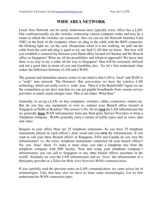
It is important to understand what is a back-up line and how and why ISDN is used as a
backup line for leased line. Please refer the following diagram.
In the above diagram, there is a Head office at Chennai and the branch office in Delhi and
both the offices are connected via a leased line through RA and RB routers. These offices
are also connected through an ISDN line as a back-up line. Back-up line means,
originally the communication is being sent through the leased line which is always up.
Suppose if the leased line is down for some reasons, then the ISDN line will
automatically come up and establish the connectivity provided both the routers RA and
RB are configured in such a way. When the leased line comes up again, the ISDN back-
up line will automatically disconnected. Thereby there is no downtime in the
connectivity. We may even use the ISDN line for all communication. But it is very
costly.
Another use of this set up is to send ‘interesting traffic’. What is meant by interesting
traffic? Suppose if you have a mail server at the Head office and you want to
communicate with the mail server at the branch office, then you can direct these SMTP
4. Compiled by A.K.Asokan. (E-mail:asokanak@hotmail.com) Page Nos.4 of 16
packets alone through the ISDN line and all other packets like http and ftp traffic through
the leased line. This has to be configured in the router’s serial interface.
HDLC: High level Data link control (HDLC) is a protocol at the data link layer. HDLC
is a point-to-point protocol used on leased lines. (Remember the following diagram? we
discussed point-to-point protocol and multi access networks in the previous OSI Layer
notes.)
High Level Data link Control (HDLC) is not intented to encapsulate multiple Network
Layer protocols across the same link. The HDLC header carries no identification of the
type of protocol being carried inside the HDLC encapsulation. Because of this, each
vendor that uses HDLC has their own way of identifying the Network layer protocol.
This means that each vendor’s HDLC is proprietary for their own equipment. To make it
clear, Cisco’s HDLC is proprietary to Cisco and it is the default encapsulation used by
Cisco routers. It will not communicate with any other vendor’s HDLC implementation.
So if you have only Cisco routers, how will you connect your routers and network to
others? If you have Cisco router and a non-cisco router with a serial connection, you must
configure PPP or another encapsulation method such as Frame Relay because the HDLC
default won’t work.
Point to point protocol (PPP) is an industry standard protocol. Because all multi-
protocol versions of HDLC are proprietary, PPP can be used to create point to point links
between different vendors’ equipment. It uses a Network Control Protocol field in the
Data link header to identify the Network Layer protocol. It allows authentication and
multi-link connections and can be run over asynchronous and synchronous links.
To summarize the above two paragraphs, protocol means ‘rules’. If Head office router
and Branch office router want to exchange communication, there must be some
‘protocols’ which both the routers must accept. HDLC (High Level Data Link Control)
and PPP (Point-to-point protocol) are two such protocols. However, if both the routers
are of the same vendor (i.e. Cisco) then HDLC is default. If both the routers are not from
the same manufacturer, then HDLC cannot be used. Here PPP can be used. However, if
both the routers are from the same vendor and HDLC is the default, still if you prefer,
PPP can be used instead of HDLC. But one side HDLC and other side PPP will not work.
5. Compiled by A.K.Asokan. (E-mail:asokanak@hotmail.com) Page Nos.5 of 16
For example, all of us can speak English. That is like HDLC. A default language. But I
know French and Mr.Neil also knows French. Then we have the option either to speak in
French or in the default language English. But if I speak German and Mr.Neil speaks in
Spanish, then we will not be able to communicate anything!
Setting up these protocols with the router’s serial interface using router commands is
what is known as ‘encapsulation’. Another thing is that IP is not the only routed protocol,
there are other networks like ATM, AppleTalk, IPX/SPX etc. apart from IP. (You may
read once again the above 3 paragraphs, if you are not sure of some concepts).
Point to point protocol (PPP) is a Data link layer protocol that can be used over either
asynchronous serial (dial-up) or synchronous serial (ISDN) media. It uses something
called the LCP (Link control protocol) to build and maintain data link connections.
Network control protocol (NCP) is used to allow multiple network layer protocol (routed
protocols – IP, ATM, AppleTalk etc.) to be used on a PPP connection. LCP is a method
of establishing, configuring, maintaining and terminating the point to point connection
and NCP is method of establishing and configuring different network layer protocols.
Since HDLC is the default serial encapsulation on Cisco serial links and it works great,
when would you use PPP?
The basic purpose of PPP is to transport layer 3 packets across a Data link layer point to
point link. It is non-proprietary, which means that if you don’t have all Cisco routers,
PPP would be needed to be encapsulated on your serial interfaces. The HDLC
encapsulation would not work because it is proprietary to the specific vendor. In addition,
we should understand that PPP can encapsulate several layer 3 routed protocols and
provide authentication, dynamic addressing and call back facility etc. This may be the
encapsulation solution of choice for you over HDLC.
PPP Authentication methods
Before establishing connectivity between two routers, it has to be authenticated each
other. There are two methods of authentication that can be used with PPP links i.e. PAP
and CHAP. PAP stands for Password Authentication Protocol and CHAP stands for
Challenge Handshake Authentication Protocol. It is upto the Network administrator to
select PAP or CHAP. However CHAP is the preferred protocol as it is a 3 way handshake
protocol.
6. Compiled by A.K.Asokan. (E-mail:asokanak@hotmail.com) Page Nos.6 of 16
Password Authentication Protocol (PAP)
The Password Authentication Protocol (PAP) is the less secure of the two methods.
When the PPP link is first established the remote node sends back to the originating
router the username and password until authentication is acknowledged (Refer diagram
below).
In the above diagram, PAP authentication is described. RA wants to communicate with
RB. As both are configured for PPP, RB knows the username and password. When RA
sends the username and password, RB verifies it and then accept/reject it so that
communication is established / not established. If the username and/or password are
wrong, then RB rejects the request to establish connectivity. PAP is not a strong
authentication protocol because the username and password are sent across the link as
‘clear text’ and hence there is no protection.
Challenge Handshake Authentication Protocol (CHAP)
The Challenge Handshake Authentication Protocol (CHAP) is used at the initial start up
of a link and at periodic checkups on the link, to make sure the router is still
communicating with the same host.
After PPP finishes its initial link establishment phase, the local router sends a challenge
request to the remote device. The remote device sends a value calculated using a one
way hash function called MD5. The local router checks this has value to make sure it
matches. If the value doesn’t match, the link is immediately terminated. See diagram
below.
7. Compiled by A.K.Asokan. (E-mail:asokanak@hotmail.com) Page Nos.7 of 16
Initially a challenge packet is sent and a response is received for that with the username
and password. Then the acceptance / rejection are established. (Both the routers send the
packets to each other to make sure their identity) (Those who work on the router can
make sure this by first encapsulating the serial interface with ppp chap and then
debugging the same while bringing the interface down and again bringing it up).
Frame Relay
Frame Relay is a bit more complex than the leased line networks we have discussed
above i.e. HDLC and PPP protocols. These leased line networks are easy to
conceptualize. Not so with Frame Relay. It can be significantly more complex, which is
why it is often represented as a cloud in networking graphics. I have made every attempt
to make you understand the concepts though only certain topologies are explained in
detail down the page. Please have the diagram referred often while you read the
explanations so that it will help you to understand it in a better way. At some places,
there will be repetition of concepts which is deliberately made in order to give an impact
for understanding. Let us try to understand Frame Relay. Read on……
Frame Relay has become one of the most popular WAN services deployed over the past
decade. It is a packet switched technology. Frame Relay technology saves money over
alternatives. By default it is classified as a non-broadcast multi access (NBMA) network,
which means that it does not send any broadcasts, such as RIP updates across the network
by default.
8. Compiled by A.K.Asokan. (E-mail:asokanak@hotmail.com) Page Nos.8 of 16
In the above diagram, there is a Head office located in Chennai and there is a Branch
office located in Delhi. In order to communicate with the two offices, both of them take
a frame relay connectivity. The infrastructure of the service provider will give you a
Virtual Circuit (VC) which is always up and running. As long as you pay the charges, it
is permanent and hence it is known as Permanent Virtual Circuit (PVC). There will be
hundreds of PVCs in a frame relay cloud.
Frame relay comes in between a leased line and a dial-up line. Under frame relay, the
Service Provider commits that any given time, you are guaranteed with a certain
bandwidth. This is known as Committed Information Rate (CIR). You can buy your
CIR. Frame relay is a technology and not a protocol.
Imagine you get a connection that looked like a leased line and acted like a leased line
but allowed you to pay for whatever portion of that leased line you actually used. That is
essentially what packet switched networks do. You pay for whatever you use. Frame
Relay provides a packet switched network to many different customers at the same time.
It is based on the assumption that all customers will never need to transmit constant data
all at the same time. An example to throw more light on the “assumption” could be that
in a bank, there are number of customers who deposited money. The bank can divert the
money for some other investment purposes on the assumption that all the customers will
not come to withdraw the money at the same time. Like that, the Frame Relay
connectivity is provided to you on the assumption that all the customers will not send
data constantly so that some portion of the bandwidth will always free and can be used by
other customers.
Frame Relay is normally implemented with standard unshielded twisted pair (UTP)
cabling from the Service provider. Devices on the subscriber premises are called
customer premises equipment (CPE). This is again connected to a device known as
Channel Service Unit / Data Service unit (CSU/DSU) and then connected to your
9. Compiled by A.K.Asokan. (E-mail:asokanak@hotmail.com) Page Nos.9 of 16
company’s router with the serial interface. The CSU/DSU (Modem) generally takes the
original signal from the provider and converts its electrical properties into the serial
format for your router. It also sometimes act as a channel bank, or multiplexer, which
breaks the channelized connection apart so that the voice and data can be separated.
The following diagram explains the cabling of frame relay from your premises till the
service provider.
10. Compiled by A.K.Asokan. (E-mail:asokanak@hotmail.com) Page Nos.10 of 16
Frame relay works by providing a portion of dedicated bandwidth to each user and also
allowing the user to exceed their guaranteed bandwidth if resources on the Telco network
are available. The providers allow their customers to buy a lower amount of bandwidth
than what they really use. This is possible because of multiplexing. There are two types
of multiplexing.
1. Frequency Division Multiplexing (FDM)
2. Statistical Division Multiplexing (SDM)
In frame relay, we use statistical division multiplexing. This means that if all the
customers are transmitting at the same time, then you are assured with the CIR (assured
bandwidth). Depends on some customers are not transmitting, you get a better bandwidth
to that extent. Anything beyond your committed information rate (CIR) is a bonus for
you and it is known as ‘burst’. The following terminologies are important.
Access rate and Committed Information Rate (CIR)
The maximum speed at which the frame relay interface can transmit is known as Access
rate. CIR the maximum bandwidth of data guaranteed to be delivered. The customers can
fix the CIR it can be 256kbps or 512 kbps etc. depends on their requirement. However,
in reality this is the average amount that the service provider will allow you to transmit. If
these values are the same, (access rate and the CIR) then the FR connection is pretty
much like a leased line. However, they can also be different values. Let us say that you
buy an access rate of T1 (1.54mbps) and a CIR of 256 kbps. By doing this, the first
256kbps of traffic will always be available to you and it is guaranteed to be delivered.
Anything beyond that is called a ‘burst’ which is the transmission that exceeds your
guaranteed 256kbps, and can be any amount upto the T1 access rate (if that amount is in
your agreement). The delivery of the 256 kbps is guaranteed. The “burst” will be
delivered on something called best effort delivery. Or may be not delivered. If your
Telco’s equipment doesn’t have the capacity to deliver at the time you transmitted, then
your frames will be discarded and the DTE (your router) will be notified so that it will re-
transmit the same. Timing is everything – you can scream data out at six times your
guaranteed rate of 256kbps (T1) only if your Telco has the capacity available on their
equipment at that moment!
We have previously discussed that multi-access networks require identification (LAN
Communication notes) and point-to-point communication doesn’t need identification of
destination. Frame relay is multi-access in nature. But it will not broadcast so we can say
non-broadcast multi-access (NBMA). (remember the example of a telephone exchange?
It will not send a call to all the lines it is connected to; but it can access multiple
destinations. In other words, it will not ‘broadcast’ but multi-access is possible.) So frame
relay is an NBMA network and since it is multi access, identification of the destination is
necessary. Non-broadcast multi access network (NBMA) means that it does not send any
11. Compiled by A.K.Asokan. (E-mail:asokanak@hotmail.com) Page Nos.11 of 16
broadcasts like RIP updates (periodic updates) across the network by default. Let us now
see what is the identifying mechanism by frame relay.
If you remember, we also have discussed previously that Ethernet on a LAN environment
works based on MAC address. Likewise frame relay is based on a number known as
DLCI numbers (Delsi numbers). DLCI stands for Data Link Connection Identifier.
(Technically, unlike MAC address, DLCIs do not specify the physical port. They specify
the logical link between two systems. It is only virtual and not physical)
LAN – MAC address (Media Access Control)
WAN (FR) – DLCI (Data Link Connection Identifier)
Every VC (virtual circuit) is identified by DLCI numbers. The Telco gives you your
DLCI numbers. DLCI 100, DLCI 150, DLCI 200 etc. DLCI has only local significance.
The Telco’s frame relay switch maintains the DLCI numbers. There cannot be two
identical numbers in a switch. If you need to call Singapore office, you need a telephone
connection with ISD facility which you may get from a Telco. Like that, in order to set
up network communication with Singapore office, you must get a frame relay connection
with a committed information rate (CIR) (your required bandwidth) from the Service
Providers. Refer the following diagram.
In the above diagram, router RA is in Chennai and router RB is in Singapore. Both the
offices are connected via a frame relay connectivity. Refer the cloud, it has an ISP switch,
which provides a PVC (Permanent virtual circuit) till the other side ISP which provided a
frame relay connectivity to the Singapore office. The PVC has DLCI numbers 102 for
chennai office and 201 for Singapore office. (Think of the PVC as a virtual pipe) When
RA wants to send a packet to RB it checks its routing table whether there is any route
12. Compiled by A.K.Asokan. (E-mail:asokanak@hotmail.com) Page Nos.12 of 16
specified to RB whose destination IP address is 20.0.0.2. See the routing table of RA
which says that any packet you want to sent to IP address 20.0.0.2, send it to Serial 0 (S0)
interface of the same router (IP address 20.0.0.1). Accordingly it sends the packet to S0
interface. Since the serial 0 interface of RA is encapsulated with frame relay, it has
another table called frame relay MAP table. Hence it looks into the Frame relay map
table as to what to do with the packet whose destination IP address is 20.0.0.2. The frame
relay map table tells yaar, for 20.0.0.2, you put the packet into DLCI number 102. It puts
the packet into DLCI number 102. Since the line is always up, it reaches the Telco’s
frame relay switch and the switch, switches the packet to DLCI number 201 of the other
side ISP through the frame relay cloud, who in turn delivers the packet to IP address
20.0.0.2 which is RB router.
Similarly, when RB router wants to send a reply packet, it sends the same to the routers
serial interface and since the interface is encapsulated by frame relay, it has a fame relay
map table which tells, to put the packet into DLCI number 201 and it reaches Chennai
DLCI 102 and delivers the same to the chennai router 20.0.0.1 (please understand that
this is the way it works and in order to understand fully, we need to understand the LMI
type and other configuration details which is omitted in this note.)
Refer the above diagram, in the frame relay cloud, there are hundreds of frame relay
switches. Frame relay is a synchronous communication means it synchronises with the
clock speed. The clocking is provided by the data communication equipment (DCE)
which is present in the Telco’s infrastructure. Frame relay specifies how to operate in the
local look which is not fully described here and it doesn’t specify how the frames are
crossing the cloud. Refer the following diagram to understand the cloud a little more.
13. Compiled by A.K.Asokan. (E-mail:asokanak@hotmail.com) Page Nos.13 of 16
The Frame Relay ‘cloud’ contains hundreds of Frame Relay switches. There are two
types of devices exist. The DCE and DTE. DCE stands for Data communications
Equipment and DTE is for Data Terminal Equipment. The DCEs are the frame switches
in the cloud. And the DTEs are the routers. The DCEs are capable of handling lot of
Virtual Circuits (VCs) simultaneously. Apart from that the DCEs provide “clocking
signal” to the DTEs. Clocking signal is needed because Frame Relay is a synchronous
protocol and the frames are ‘synchronized with the clocking signal’. There is no start bit
and stop bit needed in this case. Hence it is more efficient and faster.
For those who find it is difficult to understand please assume that your Telco will give
you a frame relay connectivity for data communication (as a telephone connectivity for
voice communication), and you must require some equipment like the router and Modem
(CSU/DSU) unit. CSU is Channel Service Unit and DSU is Data Service Unit to set up
the connectivity. For a telephone call to land in Singapore office, the Singapore office
also must have equipped with a telephone connectivity from any Telco available in
Singapore. As you don’t bother about how the Telcos communicate with each other, the
same scenario exist here as to how the Telco does the data communication through frame
relay technology, in a user perspective. The idea here is to understand that to
communicate with a remote place which is geographically and administratively doesn’t
have any boundaries, and to set up a WAN connectivity, we have certain technologies
and one of such technologies is Frame relay.
14. Compiled by A.K.Asokan. (E-mail:asokanak@hotmail.com) Page Nos.14 of 16
There are various types of frame relay connectivity.
1) Full mesh topology
2) Partial mesh topology, and
3) Hub and spoke topology
The following diagram explains the full mesh topology.
In the above diagram, the Head office (HO) is connected to 5 branch offices. All the first
branch offices are connected each other. This is known as full mesh topology and it
provided lot of redundancy and fault tolerance. Even if one link fails, the connectivity is
not completely disconnected. However, look at the diagram how many PVCs are required
to buy?! It will cost exorbitantly!. You can have partial mesh also which means may be
branch office 3 and 5 alone can be fully meshed. The alternative is Hub and spoke
topology. Refer the following diagram.
15. Compiled by A.K.Asokan. (E-mail:asokanak@hotmail.com) Page Nos.15 of 16
In the above diagram, the Head office (HO) is connected to 5 branch offices. However,
all the five branch offices are connected only to Head office and not each other. So we
need to get only five PVCs. It is less costly to that extent. The only problem with hub and
spoke topology is that, in case the router at the HO is failed, then none of the branch
offices can communicate each other. Otherwise, it is an excellent way to connect remote
locations. The hub and spoke topology is a simple and generally the easiest to set up. In a
hub and spoke topology, every device is connected to a central hub device, (a router)
which performs the routing work.
In the following diagram a hub and spoke topology is described. See that if the branch
offices have to contact each other, they have to connect through the Head office.
16. Compiled by A.K.Asokan. (E-mail:asokanak@hotmail.com) Page Nos.16 of 16
In the above diagram one new concept we are going to discuss before we close. Take a
close look at the router RA. It has only one serial interface. But it has been connected to
three branch offices located in Singapore, USA and Canada respectively. All the three
branch offices are (encapsulated with frame relay) connected to a single serial interface.
This is possible due to a new concept known as “sub-interfaces´.
What are sub-interfaces? Think of a sub-interface as a logical interface. Several sub-
interfaces will share a single hardware interface (physical interface) which is called
multiplexing. You can define sub-interfaces in the serial interface of the router. Before
creating sub-interfaces, the physical serial interface must be encapsulated and then you
can define sub-interfaces. Generally one sub-interface per PVC will be created. In our
above diagram, there are three sub-interfaces. Each sub-interface must be given
individual IP addresses. See the above diagram, the sub-interfaces are given ip addresses
viz. 172.16.1.1, 172.16.2.1 and 172.16.3.1. Sub-interfaces are of two types. 1) Point-to-
point and 2) multipoint. It is very very important to note that when you create sub-
interfaces, the physical serial interface must not be given an IP address but it has to be
encapsulated with Frame Relay.
Dear Friends, the WAN concepts described above is only to the point. You are requested
and encouraged to read lot of materials from standard publications, journals and
periodicals in order to get good understanding of the concepts. Hope this note was useful
to you. Best of luck. – asokan. (asokanak@hotmail.com).
____________________________________________