Intze Overhead Water Tank Design by Working Stress - IS Method.pdf
Lesson 04, shearing force and bending moment 01
1. Lecturer;
Dr. Dawood S. Atrushi
November 2014
Shearing Force and
Bending Moment
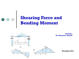
M = RA x
RA - P1
P1 (x - a1)
RA - P1 )(a2 - a1)
that point
bending
simple beam
a < x < a + b
V = RA - q (x - a)
M = RA
x - q (x - a)2 / 2
2. Content
¢ Beams
¢ Type of beams, loadings, and
reactions
¢ Shear Forces and Bending Moments
¢ Relationships Between Loads,
Shear Forces, and Bending
Moments
¢ Shear-Force and Bending-Moment
Diagrams
2 Shearing Force and Bending Moment - DAT November, 2014
3. Beams
Members which are subjected to loads
that are transverse to the longitudinal
axis are termed as the beam.
The members are either subjected to
the forces or the moment having their
vectors perpendicular to the axis of the
November, 2014
bar.
Shearing Force and 3 Bending Moment - DAT
4. both. When the load w per unit of the beam (as between A be uniformly distributed over Beams are classified according supported. Several types of Fig. 5.2. The distance L shown L
both. When the load w per unit length of the beam (as between A and B be uniformly distributed over that Beams are classified according supported. Several types of beams Fig. 5.2. The distance L shown in L
The transverse loading of a beam may consist of concentrated
loads P1, P2, Types . . . , expressed of in Beams
newtons, pounds, or their multiples,
kilonewtons and kips (Fig. 5.1a), of a distributed load w, expressed
in N/m, kN/m, lb/ft, or kips/ft (Fig. 5.1b), or of a combination of
both. When ① the Statically load w per Determinate unit length has a beams
constant value over part
of the beam (as between A and B in Fig. 5.1b), the load is said to
be uniformly distributed over that part of the beam.
Beams are classified according to the way in which they are
supported. Several types of beams frequently used are shown in
Fig. 5.2. The distance L shown in the various parts of the figure is
November, 2014
L
(b) Overhanging beam
L
(c) Cantilever beam
(b) Distributed load
A
B
C
Fig. 5.1 Transversely loaded
beams.
(a) Simply supported beam
Statically
Determinate
Beams
Statically
Indeterminate
Beams
L1 L2
(d) Continuous beam
L
(b) Overhanging beam
L
Beam fixed at one end
and simply supported
(e)
(b) Distributed load
A
B
C
Fig. 5.1 Transversely loaded
beams.
(a) Simply supported beam
Determinate
Indeterminate
L1 L2
(d) Continuous beam
L
(b) Overhanging beam
L
Beam fixed at one end
and simply supported
(e)
4 Shearing Force and Bending Moment - DAT
5. Beams are classified according to the way in which they are
of the beam (as between A and B in Fig. 5.1b), the load is said to
be uniformly distributed over that part of the beam.
supported. Several types of beams frequently used are shown in
Fig. 5.2. The distance L shown in the various parts of the figure is
Beams are classified according to the way in which they are
Types of Beams
supported. Several types of beams frequently used are shown in
Fig. 5.2. The distance L shown in the various parts of the figure is
② Statically Indeterminate beams
Fig. 5.2 Common beam support configurations.
November, 2014
316
L
(a) Simply supported beam
Statically
Determinate
Beams
Statically
Indeterminate
Beams
L1 L2
(d) Continuous beam
configurations.
L
(b) Overhanging beam
L
Beam fixed at one end
and simply supported
at the other end
(e)
L
(c) Cantilever beam
L
( f ) Fixed beam
configurations.
L
(b) Overhanging beam
L
Beam fixed at one end
and simply supported
at the other end
(e)
L
(c) Cantilever beam
L
( f ) Fixed beam
5 Shearing Force and Bending Moment - DAT
6. P1
B C
B C
(a) Concentrated loads
w
P2
A D
(b) Distributed load
A
B
C
Fig. 5.1 Transversely loaded
beams.
Type of Loads
November, 2014
P1
(a) Concentrated loads
w
P2
A D
(b) Distributed load
A
B
C
Fig. 5.1 Transversely loaded
beams.
a) Concentrated load (single
force)
b) Distributed load
(measured by their
intensity):
i. Uniformly distributed load
(uniform load)
ii. Linearly varying load
c) Couple
6 Shearing Force and Bending Moment - DAT
7. (a) Roller Support – resists vertical forces only
¢ Pinned support or hinged support.
Hinge support or pin connection – resists horizontal and
November, 2014
Type of Reactions
(b) Hinge support or pin connection – resists horizontal and
vertical forces
vertical forces
Hinge and roller supports are called as simple supports
(c) Fixed support or built-in end
Shearing Force and 7 Bending Moment - DAT
Hinge and roller supports are called as simple supports
8. ¢ Roller support
November, 2014
Type of Reactions
Solid Mechanics
force and bending moment along the length of the
beam.
These diagrams are extremely useful while designing the
beams for various applications.
Supports and various types of beams
(a) Roller Support – resists vertical forces only
(b) Hinge support or pin connection – resists horizontal and
vertical 8 forces
Shearing Force and Bending Moment - DAT
9. and roller supports are called as simple supports
¢ Fixed support
November, 2014
Type of Reactions
Hinge and roller supports are called as simple supports
(c) Fixed support or built-in end
Fixed support or built-in end
Shearing Force and 9 Bending Moment - DAT
10. simply supported beam (simple beam)
Calculate the reaction forces of on of
the below members
cantilever beam (fixed end beam)
with an overhang
November, 2014
shear
beams
Reactions
cantilever beam (fixed end beam)
beam with an overhang
Shearing Force and 10 Bending Moment - DAT
11. a)
MB = 0 - RA L + (P1 sin ) (L - a) + P2 (L - b) + q c2 / 2 = 0
(P1 sin ) (L - a) P2 (L - b) q c2
RA = CCCCCCC + CCCC + CC
L L 2 L
(P1 sin ) a P2 b q c2
12 P3 q1 b q1 b
RB = CCCCC + CC + CC
MA = 0 L MA = CC + L CC (L – 2 L
2b/3) + CC (L – b/3)
13 2 2
November, 2014
for the overhanging beam
MB 0 - RA L + P4 (L– a) + M1 = 0
MA = 0 - P4 2
a + RB L + M1 = 0
P4 (L– a) + M1 P4 a - M1
RA = CCCCCC RB = CCCC
L L
4.3 Shear Forces and Bending Moments
RA = CCCCCCC + CCCC + CC
L L 2 L
(P1 sin ) a P2 b q c2
RB = CCCCC + CC + CC
L L 2 L
for the cantilever beam
Fx = 0 HA = 5 P3 / 13
12 P3 (q1 + q2) b
Fy = 0 RA = CC + CCCCC
13 2
12 P3 q1 b q1 b
MA = 0 MA = CC + CC (L – 2b/3) + CC (L – b/3)
13 2 2
for the overhanging beam
MB = 0 - RA L + P4 (L– a) + M1 = 0
MA = 0 - P4 a + RB L + M1 = 0
P4 (L– a) + M1 P4 a - M1
2
for the cantilever beam
Fx = 0 HA = 5 P3 / 13
12 P3 (q1 + q2) b
Fy = 0 RA = CC + CCCCC
13 2
b)
c)
Shearing Force and 11 Bending Moment - DAT
12. Shear Forces and Bending
Moments
At any point (x) along its length, a beam
can transmit a bending moment M(x)
and a shear force V(x).
November, 2014
Bending-Moment Diagrams
support beam AB
= P a / L
Shearing Force and 12 Bending Moment - DAT
13. MA = 0 - P4 a + RB L + M1 = 0
MB = RA L P4 (L– a) + M1 = 0
MA = 0 - P4 a + RB L + M1 = 0
B.F.MA = 0 - P4 a + RB L + M1 = 0
P4 (L– a) + M1 P4 a - M1
RA = CCCCCC RB = CCCC
Shear Forces P4 (L– and a) + Bending M1 Moments
P4 a - M1
RA = CCCCCC RB = CCCC
Consider a cantilever beam with a
I
II A B A
¢ P4 Consider (L– a) + M1 a cantilever L P4 a - beam with a
concentrated load P L
M1
applied at the
end A, at the cross section mn, the
shear force and bending moment are
found
Look RA at = CCCCCC the L FBD of an elemental RB = CCCC
L
length dx of the above loaded infinitesimal L length, the distributed I
L
load can be considered as a Uniformly (UDL) with constant magnitude w(x) over the differential length dx.
It is now necessary to equate the equilibrium of the element. Starting
14.
15.
16.
17. ·
concentrated load P applied at the end
4.3 Shear Forces and Bending Moments
Consider a cantilever beam with a
concentrated load P applied at the end
A, at the cross section mn, the shear
force and bending moment are found
Shear Forces and Bending Moments
Consider a cantilever beam with a
concentrated load P applied at the end
4.3 Shear Forces and Bending Moments
Consider a cantilever beam with a
concentrated load P applied at the end
A, at the cross section mn, the shear
force and bending moment are found
at the cross section mn, the shear
force and bending moment are found
F V x w x dx V x dV x y Dividing by dx in the limit as dxĺ0,
n¦ § dx
0 0 ¸¹
the cross section mn, the shear
and bending moment are found
Fy = 0 V = P
M = 0 M = P x
M P a o ĺ
25. dM x +
P
L
a
RAY=(1-a/L)P RBY=Pa/L
RAY=(F.B.D. (global equilibrium)
II
Fig. 5.3 FBD of beam cut before force Step A: Cut beam just before the force P (i.e. Section I-I), and including the unknown shear force and bending moment as in Fig. Take moments about the right hand end (O):
29. Sign Convention
¢ The shear force tends
to rotate the material
clockwise is defined
as positive
¢ The bending moment
tends to compress
the upper part of the
and elongate
the lower part is
defined as positive
November, 2014
= 0 M = P x
conventions (deformation sign conventions)
shear force tends to rotate the
clockwise is defined as positive
bending moment tends to compress
part of the beam and elongate the
part is defined as positive
3
M = 0 M = P x
conventions (deformation sign conventions)
shear force tends to rotate the
material clockwise is defined as positive
bending moment tends to compress
upper part of the beam and elongate the
part is defined as positive
3
M = 0 M = P x
conventions (deformation sign conventions)
shear force tends to rotate the
material clockwise is defined as positive
bending moment tends to compress
upper part of the beam and elongate the
part is defined as positive
Shearing Force and 14 Bending Moment - DAT
30. Example 1
A simple beam AB supports a force P
and a couple M0, find the shear V and
bending moment M at
a) x = L/2
b) x = (L/2)+
November, 2014
supports a force P
the shear V and
(b) at x = (L/2)+
Shearing Force and 15 Bending Moment - DAT
31. Example 2
A cantilever beam AB subjected to a
linearly varying distributed load as
shown, find the shear force V and the
bending moment M
November, 2014
= RA (L/2) + P (L/4) = P L / 8 - M0 / 2
= (L/2)+ [similarly as (a)]
= - P / 4 - M0 / L
= P L / 8 + M0 / 2
cantilever beam AB subjected to a
varying distributed load as shown, find
V and the bending moment M
q0 x / L
0 - V - 2 (q0 x / L) (x) = 0
Shearing Force and 16 Bending Moment - DAT
32. M + 2 (q0 x / L) (x) (x / 3) = 0
Example 3
An overhanging beam ABC is supported to
an uniform load of intensity q and a
concentrated load P, calculate the shear
force V and the bending moment M at D
- q0 x3 / (6 L)
- q0 L2 / 6
overhanging beam ABC is
uniform load of intensity
concentrated load P, calculate
V and the bending
D
17 Shearing Force and Bending Moment - DAT November, 2014
33. x 5 + 28 x 2 + 6 x 5 x 2.5 + M = 0
= 69 kN-m
Relationships Between Loads,
Shear Forces, and Bending
Moments
body diagram of the right-hand part, same results can be
a) Consider an element of a beam of
length dx subjected to distributed
loads q.
Between Loads, Shear Forces, and Bending Moments
element of a beam of length
distributed loads q
forces in vertical direction
November, 2014
Shearing Force and 18 Bending Moment - DAT
5
34. Fy = 0 V - q dx - (V + dV) = 0
Equilibrium of forces in vertical direction
Fy = 0 V - q dx - (V + dV) = 0
or dV / dx = - q
Fy = 0 V - q dx - (V + dV) = 0
integrate between two points A and B
integrate between two points A and B
Integrate B between two B
points A and B;
Н dV = -Н q dx
A A
i.e. B
VB - VA = -Н q dx
A
= - (area of the loading diagram between the area of loading diagram may be positive or negative
moment equilibrium of the element
= - (area of the loading diagram between A
= - (area of the loading diagram between the area of loading diagram may be positive November, 2014
or negative
or dV / dx = - q
or dV / dx = - q
integrate between two points A and B
B B
Н dV = -Н q dx
B B
Н A dV = -Н A
q dx
A A
i.e. B
i.e. B
VB - VA = -Н q dx
VB - VA = -Н q dx
A
A
and B)
= - (area of the loading diagram between the area of loading diagram may be positive or negative
Shearing Force and 19 Bending Moment - DAT
35. = - (area of the loading diagram between A
the area of loading diagram may be positive or negative
moment equilibrium of the element
= - (area of the loading diagram between A and B)
= - (area of the loading diagram between A the area of loading diagram may be positive or negative
moment equilibrium of the element
area of loading diagram may be positive or negative
Moment equilibrium of the element
moment equilibrium of the element
M = 0 - M - q dx (dx/2) - (V + dV) dx + M or dM / dx = V
maximum (or minimum) bending-moment occurs at i.e. at the point of shear force V = 0
= 0 - M - q dx (dx/2) - (V + dV) dx + M + dM = 0
or dM / dx = V
M = 0 - M - q dx (dx/2) - (V + dV) dx + M + dM or dM / dx = V
maximum (or minimum) bending-moment occurs at dM i.e. at the point of shear force V = 0
maximum (or minimum) bending-moment occurs at dM / dx = Maximum (or minimum) bending-moment
point of shear integrate occurs force at between V dM/= dx two = 0
0, points i.e. at the A point and of
B
integrate between shear two points force V A = and 0.
B
November, 2014
integrate between two points A and B
B B
Н dM = Н V dx
A A
B B
Н dM = Н V dx
A A
B B
Н dM = Н V dx
A A
Shearing Force and 20 Bending Moment - DAT
i.e. B
36. maximum (or minimum) bending-moment occurs at i.e. at the point of shear force V = 0
integrate between two points A and B
Integrate between two points A and B
= (area of the shear-force diagram between this equation is valid even when concentrated loads between A and B, but it is not valid if a couple and B
November, 2014
or dM / dx = V
maximum (or minimum) bending-moment occurs at i.e. at the point of shear force V = 0
integrate between two points A and B
B B
Н dM = Н V dx
A A
B B
Н dM = Н V dx
A A
i.e. B
i.e. B
MB - MA = Н V dx
MB - MA = Н A
V dx
A
= (area of the loading = (area diagram of the between shear-force A
diagram between this and equation B)
is valid even when concentrated loads between A and B, but it is not valid if a couple and 21 B
Shearing Force and Bending Moment - DAT
37. b) Consider an element of a beam of
length dx subjected to concentrated
load P.
November, 2014
concentrated loads
equilibrium of force
V - P - (V + V1) = 0
or V1 = - P
e. an abrupt change in the shear force occurs
any point where a concentrated load acts
Shearing Force and 22 Bending Moment - DAT
38. concentrated concentrated loads
equilibrium Equilibrium of force
of force;
i.e. an abrupt
V - P - (V + V1) = 0
change in the
or V1 = - P
shear force
occurs at any
point where a
i.e. an abrupt change in the shear force occurs
concentrated
at any Equilibrium point where of a concentrated moment;
load acts
equilibrium of moment
since the length dx of the element is infinitesimally November, 2014
is also infinitesimally small, thus, the bending moment does - M - P (dx/2) - (V + V1) dx + M + M1 or M1 = P (dx/2) + V dx + V1 dx M 0
loads
equilibrium of force
V - P - (V + V1) = 0
or V1 = - P
i.e. an abrupt change in the shear force occurs
at any point where a concentrated load acts
equilibrium of moment
- M - P (dx/2) - (V + V1) dx + M + M1 = 0
or M1 = P (dx/2) + V dx + V1 dx M 0
load acts.
Since the length dx of the element is infinitesimally small,
i.e. M1 is also infinitesimally small, thus, the bending
moment does not change as we pass through the point of
application of a concentrated load.
since the length dx of the element is infinitesimally small, i.e. M1
is also infinitesimally small, thus, the bending moment does not change as
we pass through the point of application of a concentrated load
Shearing Force and 23 Bending Moment - DAT
39. c) Consider an element of a beam of
length dx subjected to concentrated
loads in form of couples, M0.
November, 2014
- M - P (dx/2) - (V + V1) dx + M + M1 = 0
M1 = P (dx/2) + V dx + V1 dx M 0
the length dx of the element is infinitesimally small, i.e. M1
infinitesimally small, thus, the bending moment does not change as
through the point of application of a concentrated load
the form of couples
equilibrium of force V1 = 0
Equilibrium of force;
V1 = 0
change in shear force at the point of
application of a couple
equilibrium of moment
Shearing Force and 24 Bending Moment - DAT
M + M0 - (V + V1) dx + M + M1 = 0
40. equilibrium of force V1 = 0
i.e. no change in shear force at the point of
¢ i.e. no change in shear force at the point
of application of a couple.
November, 2014
application of a couple
equilibrium of moment
Equilibrium of moment;
- M + M0 - (V + V1) dx + M + M1 = 0
or M1 = - M0
the bending moment changes abruptly at a point couple
¢ The bending moment changes abruptly
at a point of application of a couple.
Shearing Force and 25 Bending Moment - DAT
41. Shear-Force and Bending-
Moment Diagrams
Concentrated loads
Consider a simply support beam AB with
a concentrated load P
4.5 Shear-Force and Bending-Moment Diagrams
concentrated loads
consider a simply support beam AB
with a concentrated load P
RA = P b / L RB = P a / L
Shear-Force and Bending-Moment Diagrams
concentrated loads
consider a simply support beam AB
concentrated load P
= P b / L RB = P a / L
0 x a
V = RA = P b / L
M = RA x = P b x / L
V = RA = P b / L
M = RA x = P b x / L
note that dM / dx = P b / L = V
November, 2014
Shear-Force and Bending-Diagrams
concentrated loads
a simply support beam AB
concentrated load P
for 0 x a
P b / L RB = P a / L
x a
= RA = P b / L
Shearing Force and 26 Bending Moment - DAT
42. consider a simply support beam AB
with a concentrated load P
RA = P b / L RB = P a / L
with a concentrated load P
RA = P b / L RB = P a / L
concentrated load P
= P b / L RB = P a / L
0 x a
V = RA = P b / L
M = RA x = P b x / L
note that dM / dx = P b / L = V
with a concentrated load P
RA = P b / L RB = P a / L
/ L RB = P a / L
x a
RA = P b / L
RA x = P b x / L
that dM / dx = P b / L = V
= P b / L RB = P a / L
RA = P b / L RB = P a / L
for 0 x a
for 0 x a
RA for 0 x a
V = RA = P b / L
M = RA x = P b x / L
note that dM / dx = P b / L = V
V = RA = P b / L
M = RA x = P b x / L
note that dM / dx = P b / L = V
for 0 x a
for 0 x a
V = RA = P b / L
M = RA x = P b x / L
note that dM / dx = P b / L = V
V = P b / L
M = RA x = P b x / L
note that dM / dx = P b / L = V
V = RA = P b / L
M = RA x = P b x / L
note that dM / dx = P b / L = V
for a x L
for a x L
V = RA - P = - P a / L
M = RA x - P (x - a) = P a (L - x) / L
note that dM / dx = - P a / L = V
L
RA - P = - P a / L
RA x - P (x - a) = P a (L - x) / L
x L
V = RA - P - P a / L
M = RA x - P (x - a) = P a (L - x) / L
note that dM / dx = - P a / L = V
V = RA - P = - P a / L
M = RA x - P (x - a) = P a (L - x) / L
note that dM / dx = - P a / L = V
for a x L
V = RA - P = - P a / L
M = RA x - P (x - a) = P a (L - x) / L
note that dM / dx = - P a / L = V
for a x L
V = RA - P = - P a / L
M = RA x - P (x - a) = P a (L - x) / L
note that dM / dx = - P a / L = V
V - P = - P a / L
M = RA x - P (x - a) = P a (L - x) / L
note that dM / dx = - P a / L = V
V = RA - P = - P a / L
M = RA x - P (x - a) = P a (L - x) / L
note that dM / dx = - P a / L = V
November, 2014
= P b / L RB = P a / L
RA = P b RB = P a / L
for 0 x a
for 0 x a
V = RA = P b / L
M = RA x = P b x / L
note that dM / dx = P b / L = V
V = RA = P b / L
M = RA x = P b x / L
note that dM / dx = P b / L = V
RA for a x L
for a x L
for a x L
V = RA - P = - P a / L
M = RA x - P (x - a) = P a (L - x) / L
note that dM / dx = - P a / L = V
that dM / dx = - P a / L = V
with Mmax = P a b / L
with Mmax = P a b / L
RA = P b / L RB = P a / L
for 0 x a
V = RA = P b / L
M = RA x = P b x / L
note that dM / dx = P b / L = V
for a x L
V = RA - P = - P a / L
M = RA x - P (x - a) = P a (L - x) / L
note that dM / dx = - P a / L = V
with Mmax = P a b / L
Shearing Force and 27 Bending Moment - DAT
with Mmax = P a b / L
with Mmax = P a b / L
with Mmax = P a b / L
RB = P a / L
a
= P b / L
= P b x / L
dM / dx = P b / L = V
L
- P = - P a / L
- P (x - a) = P a (L - x) / L
dM / dx = - P a / L = V
Mmax = P a b / L
43. - P = - P a / L
With Mmax = Pab/L
November, 2014
RA x - P (x - a) = P a (L - x) / L
dM / dx = - P a / L = V
= P a b / L
V - Diagram
M - Diagram
Shearing Force and 28 Bending Moment - DAT
44. Uniform loads
Consider a simply support beam AB with
a uniformly distributed load of constant
intensity q;
November, 2014
8
load
consider a simple beam AB with a
distributed load of constant
q
RA = RB = q L / 2
V = RA
- q x = q L / 2 - q x
Shearing Force and 29 Bending Moment - DAT
x - q x (x/2) = q L x / 2 - q x2 / 2
M = RA
45. - q x = q L / 2 - q x
- q x (x/2) = q L x / 2 - q x2 / 2
note that dM / dx = q L / 2 - q x / 2 = V
V - Diagram M - Diagram
Mmax = q L2 / 8 at x = L / 2
November, 2014
= RB = q L / 2
V = RA
- q x = q L / 2 - q x
x - q x (x/2) = q L x / 2 - q x2 / 2
RA M = RA
note that dM / dx = q L / 2 - q x / 2 = V
= RB = q L / 2
Mmax = q L2 / 8 at x = L / 2
RA V = RA - q x = q L / 2 - q x
M = RA
x - q x (x/2) = q L x / 2 - q x2 / 2
several concentrated loads
- q x
x2 / 2
x / 2 = V
for 0 x a1 V = RA M = RA x
M1 = RA a1
Shearing Force and 30 Bending Moment - DAT
for a1 x a2 V = RA - P1
RB = q L / 2
RA
dM / dx = q L / 2 - q x / 2 = V
= q L2 / 8 at x = L / 2
concentrated loads
V = RA M = RA x
46. = RB = q L / 2
V = RA
- q x = q L / 2 - q x
- q x = q L / 2 - q x
x - q x (x/2) = q L x / 2 - q x2 / 2
V = RA
M = RA
x - q x (x/2) = q L x / 2 - q x2 / 2
M = RA
Several concentrated loads
Consider a simply support beam AB with
a several concentrated pi;
RA x - q x (x/2) = q L x / 2 - q x2 / 2
note that dM / dx = q L / 2 - q x / 2 = V
note that dM / dx = q L / 2 - q x / 2 = V
Mmax = q L2 / 8 at x = L / 2
Mmax = q L2 / 8 at x = L / 2
for 0 x a1 V = RA M = RA x
M1 = RA a1
for a1 x a2 V = RA - P1
M = RA x - P1 (x - a1)
- M1 = (RA - P1 )(a2 - a1)
November, 2014
x (x/2) = q L x / 2 - q x2 / 2
dM / dx = q L / 2 - q x / 2 = V
= q L2 / 8 at x = L / 2
loads
several concentrated loads
several concentrated loads
V = RA M = RA x
= RA a1
V = RA - P1
= RA x - P1 (x - a1)
M2
for 0 x a1 V = RA M = RA x
M1 = RA a1
for a1 x a2 V = RA - P1
M = RA x - P1 (x - a1)
M2
M1 = (RA - P1 )(a2 - a1)
RA = RB = q L / 2
= RA
- q x = q L / 2 - q x
M = RA
note that dM / dx = q L / 2 - q x / 2 = V
Mmax = q L2 / 8 at x = L / 2
concentrated loads
x a1 V = RA M = RA x
M1 = RA a1
a1 x a2 V = RA - P1
M = RA x - P1 (x - a1)
M2
- M1 = (RA - P1 )(a2 - a1)
31 Shearing Force and Bending Moment - DAT
47. M1 several concentrated loads
several concentrated loads
= RA a1
V = RA - P1
= RA x - P1 (x - a1)
for 0 x a1 V = RA M = RA x
several concentrated loads
M1 = RA a1
for 0 x a1 V = RA M = RA x
M2
for a1 x a2 V = RA - P1
M1 = RA a1
V - Diagram
- M1 = (RA - P1 )(a2 - a1)
M = RA x - P1 (x - a1)
for a1 x a2 V = RA - P1
others
because V = 0 at that point
M = RA x - P1 (x - a1)
M2
- M1 = (RA - P1 )(a2 - a1)
similarly for others
M2 = Mmax because V = 0 at that point
shear-force and bending
diagrams for the simple beam
November, 2014
M1 = RA a1
for a1 x a2 V = RA - P1
M = RA x - P1 (x - a1)
M2
- M1 = (RA - P1 )(a2 - a1)
similarly for others
M2 = Mmax because V = 0 at that point
Example 4-4
construct the shear-force and bending
-moment diagrams for the simple beam
AB
Example 4-4
for 0 x a1 V = RA M = RA x
M1 = RA a1
for a1 x a2 V = RA - P1
M = RA x - P1 (x - a1)
M2
- M1 = (RA - P1 )(a2 - a1)
similarly for others
M2 = Mmax because V = 0 at that point
M - Diagram
Example 4-4
construct the shear-force and bending
-moment diagrams for the simple beam
concentrated loads
= RA M = RA x
M1 = RA a1
V = RA - P1
= RA x - P1 (x - a1)
M2
- M1 = (RA - P1 )(a2 - a1)
others
because V = 0 at that point
- M1 = (RA - P1 )(a2 - a1)
similarly for others
M2 = Mmax because V = 0 at that point
Example 4-4
construct the shear-force and bending
32 Shearing Force and Bending Moment - DAT
-moment diagrams for the simple beam
48. Example 4
Construct the shear force and bending
moment diagrams for the simple beam
AB.
November, 2014
M = RA x - P1 (x - a1)
M2
- M1 = (RA - P1 )(a2 - a1)
others
because V = 0 at that point
shear-force and bending
diagrams for the simple beam
b + 2c) / 2L
b + 2a) / 2L
Shearing Force and 33 Bending Moment - DAT
49. Example 5
Construct the V- and M-diagram for the
cantilever beam supported to P1 and P2.
November, 2014
= q b (2L - b) / 8
= c = 0 (uniform loading over the entire span)
= q L2 / 8
V- and M-dia for the
supported to P1 and P2
P2 MB = P1 L + P2 b
a
P1 M = - P1 x
Shearing Force and 34 Bending Moment - DAT
50. Example 6
Construct the V- and M-diagram for the
cantilever beam supporting to a
constant uniform load of intensity q.
November, 2014
and M-dia for the
to a constant uniform
MB Shearing Force and 35 Bending Moment - DAT
= q L2 / 2
51. Example 7
An overhanging beam is subjected to a
uniform load of q = 1 kN/m on AB and a
couple M0 = 12 kN-m on midpoint of BC.
Construct the V- and M-diagram for the
beam.
November, 2014
x
= V - 0 = V = -Н q dx = - q x
0
x
= M - 0 = M = -Н V dx = - q x2 / 2
0
overhanging beam is subjected to a
q = 1 kN/m on AB
M0 = 12 kN-m on midpoint
construct the V- and M-dia for
Shearing Force and 36 Bending Moment - DAT
52. Thank You
37 Shearing Force and Bending Moment - DAT November, 2014