SlideShare ist ein Scribd-Unternehmen logo
1 von 74
FSSS
FURNACE SAFEGUARD SUPERVISORY SYSTEM
. For 210 MW Unit at Koradi.
FSSS SYSTEM
• 1. CLASS ROOM SESSION–
UNDERSTANDING BASIC CONCEPTS & LOGICS
OF FUEL FIRING.
• 2. SITE VISIT-
PRACTICAL IMPLEMENTATION OF THE SYSTEM.
FUEL FIRING EQUIPMENTS,CONTROL DESK
(operation of equipments), RELAY PANELS,ALARM
& INDICATION .
FURNACE
• 1. CONSTRUCTION
• 2.OPERATION
• 3.MAINTENANCE
• 4.INTERLOCK & PROTECTION-
(LOGICS & CONCEPTS.)
Furnace associated
terminologies
a. Hanging Structure.
b. Elevation- AB,CD,EF & Corner- 1,2,3,4.
c. Wind box-A/B.
d. Scanner fans- Auxiliary Dampers
e. Burner Tilt- 13 Compartments.
f. Tangential fuel firing system-
Fire ball at the centre
g. Igniters-
h. Fuel System- FO, LDO, Oil guns,
Hydro motor valves.
Instrument air & Service air system
i. Soot blowing system.
BOILER
• CONSTRUCTION- Mechanical
• AUXILLIARIES Associated with –
( Interlocks & Protections of auxiliaries)
• OPERATION & Control of Boiler.
• FUEL FIRING SYSTEM-
Equipments & Control system-(FSSS)
FUEL FIRING EQUIPMENTS-
• MECHANICAL EQUIPMENTS & THEIR
CONSTRUCTION
• CONCEPTS & LOGICS INVOLVED IN FUEL FIRING
SYSTEM
• INTERLOCKS & PROTECTIONS INVOLVED
• SEQUENCE OF OPERATING FUEL SYSTEM.
EFFECTIVE FUEL FIRING–
MEANS PROPER COMBUSTION
• FURNACE HAZARDS-
EXPLOSION -- IMPLOSION
• NFPA 85-The National Fire Protection Association
(NFPA) codes, such as
NFPA 85: Boiler and Combustion Systems
Hazards Code are dedicated to fire and furnace
explosion and implosion protection
• For proper combustion of fuel in the furnace ,
adequate supply of air must be supplied and
intimately mixed with a supply of combustible
material ( FUEL ) which has been presented in
the correct condition.
• HOW TO AVOID?
• Boiler Furnace explosion may be avoided by
timely purging and stoppage of leakage of fuel
oil in furnace.
Practical means of avoiding furnace explosion is
the prevention of an explosive accumulation
• Furnace explosion is rare, but very severe in
nature. This situation exists because furnace is
supplied with explosive accumulation.
• Just a minute part of those explosive charges
receive sufficient ignition energy to actually
cause an explosion.
• The Furnace explosion requires both
sufficient explosive accumulation and
sufficient energy for ignition
CAUSE OF EXPLOSION- FURNACE PRESSURE-
• Why to maintain furnace pressure ?
• Furnace Pressure is one such very important
parameter, which needs continuous control,
protection & monitoring. This is very important
from safety of the boiler.
• In case of very low and very high pressure, the
furnace may subject to explosion and implosion,
which may result in Boiler Structure and pressure
parts, tubes damage and furnace deformation.
• Explosion Factor = (Mass/Furnace Volume) x
Composition Change/Elapsed Time)
The furnace explosion occurs due to:
a) Improper purging of the furnace and air.
b) Inadequate ignition procedures.
c) Maintaining fuel supply for too long a
period without establishing combustion.
d) Re-lighting burners too soon after previous
flame out.
e) Introduction of main fuel without ensuring
adequate ignition energy.
FURNACE IMPLOSION
• CONDITIONS UNDER WHICH FURNACE IMPLOSION WILL
OCCUR-
• 1)Boilers with both induced and forced draft fans may
become unbalanced especially if the forced draft unit
becomes tripped and the induced fan unit remains in full
operation.
• The induced draft fan will produce an excessive draft in the
furnace and create the real likelihood of furnace implosion.
• Negative pressure excursion of sufficient magnitude to
cause structural damage.
• Incase of ID Fan is capable of producing more suction head
than the boiler structure is capable of withstanding.
• Control malfunction and / or operator error, establish such
conditions.
• 2) The other process called flame collapse or
flameout effect. The negative pressure
excursion following a fuel trip and loss of
furnace flame, in order to realistically evaluate
pit falls and prevention techniques
CONDITIONS FOR PROPER
COMBUTION OF FUEL
• It is the purpose of the burner to present the fuel in
suitable condition for proper combustion.
• Generally this means atomizing the fuel and giving it some
axial (for penetration) and angular (for mixing) velocity.
• For effective atomization the viscosity of the fuel is critical.
• For fuels heavier than gas or diesel oils some degree of
heating is required.
• It should be noted that the temperature of the fuel should
not be allowed to raise too high as this can not only cause
problem with fuel booster pumps but also can cause flame
instability due to premature excessive gasification.
• The smaller the droplet size the greater the surface
areas/volume ratio is, this increases evaporation, heating
and combustion rate.
DIAGRAM OF HOW THE FUEL BURNS
INSIDE THE FURNACE?
TYPE OF FUEL-
LDO (LIGHT DIESEL OIL )
FO (FURNACE OIL )
PULVARISED COAL
Equipments involved-
1.IGNITOR-
TRIP VALVES, HEA IGNOTOR ASSEMBLY-
SPARK ROD * SPARK TIP
EXCITATION TRANSFORMER. & CKT.
IGNITOR AIR FANS-
FOR PROVIDING COOLING AIR TO IGNITOR TIP
2.OIL GUNS-
• TRIP VALVES-
OIL HYDROMOTOR VALVES-
PNEUMATIC VALVES
• ATOMISING VALVES- STEAM & AIR
• SCAVENGE VALVES-
3.PULVARISED COAL-
– COAL MILL- Ignition Energy availability condition.
– COAL FEEDER- To regulate amount of coal input
in the Furnace.
– HAG & COLD AIR DAMPER
4.AIR SYSTEM-
13 COMPARMENTS
• WINDBOX TO FURNACE DIFFERENTIAL
PRESSURE MONITORING.
• AUXILLIARY AIR DAMPERS-
Modulating to control AIR flow
5.FLAME MONITORING SYSTEM-
• BURNER TILTS-
To maintain temp.& Keep fire ball at centre.
SCANNERS-
Flame scanners used to sense flame in boiler
to detect flame failure to avoid boiler furnace
Explosion.
Flame Scanners & Fire ball scanners.
6.SCANNER System-
• SCANNER LOGIC-
• IGNITION ENERGY
• FLAME FAILURE TRIPPING
Flame intensity
How the Fuel is Fired in Furnace?
Coal firing
FSSS System—
Furnace safeguard supervisory system
This system supervises the Furnace operations,
controls process parameters & Protects the
Furnace under abnormal operating conditions.
The functions of FSSS mainly include:
1. To Safe guard the Furnace against “Abnormal
operating conditions.”
2. To Supervise the condition of furnace during fuel
firing .
INTRODUCTION
Furnace safeguard supervisory system popularly called FSSS
continuously monitors the operations related to fuel admission and some
other vital parameters to ensure safety of the Boiler.
Generally furnace oil or any kind of fuel is susceptible to
explosion hazards. Majority of explosion occurs during start up, shut
down and low load operations. There are many steps that must be
followed by the operator to admit a fuel in to the furnace safely and
properly. In high capacity boilers, where fuel input rate is very high major
furnace explosions can result from the ignition of un-burnt fuel
accumulated in the first one or two seconds. Human reaction time to such
situations is inadequate. So there a proper burner management system
called as FSSS is installed in the Boilers. Every operation related to fuel
admission is accomplished through FSSS
Advantages of FSSS system –
a. Continuously monitors the operations related to
fuel admission & vital parameters, to ensure safety of boiler.
b. Every fuel is susceptible to Explosion hazards.
Majority of explosions occurs during start-up,
plan Shut-down, & Low load conditions.
c. Boiler operator has to take many important &
sequential steps to admit fuel in the furnace,
safely & properly . If it is left to the judgment of
the operator, then high probability of error will be
involved. This system helps to reduce the error.
D Accuracy of Ignition energy is an important factor
for proper combustion of fuel.
E System logics allows / Dis allows fuel admission in
the furnace by monitoring furnace condition.
FSSS Helps us to provide:---
 Monitoring OF processes parameter
 Control & Protection OF processes parameter
whenever IT deviates from its normal value.
System logics senses dangerous situations &
does not allow Fuel admission in such situations &
thus protects the furnace, if reqd, by giving trip
commands to boiler.
What is meant by Boiler trip ???
 Every type of Fuel is cut-off from the Furnace .
 NO Flame condition is established..
FSSS System consists of -- Hardware & Software.
Hardware
 Panels in control room - Consists of Relays, Timers.
 Control Desk-- -For operation of fuel firing equipments.
(For Monitoring & Control of parameters )
 Indication & Alarm system.— For alertness & actions.
UNIT
PANEL- 1
UNIT
PANEL-2
AB
Elevation
CD
Elevation
EF
Elevation
Coal mill
“A”
Coal mill
“B”
Coal mill
“C”
Coal mill
“D”
Coal mill
“E & F”
FSSS Panels lay-out :- (For Relay based system )
Software--
 Electrical drawings- (Logic Diagrams. )
 Supply system---220 V DC & 110 V AC
1) 110 v ac FROM IPDB ( Instrument panel distribution board.)
used for relay logic system.
2) 220 V DC FROM DCDB ( DC distribution board),
for relay logics & “TRIPPING Logic”.
3) 24 V DC for Indication supply. (Console indications)
What are the Abnormal operating conditions ?
 Flame failure,
 Furnace pressure inadequate-High / Low.
 Loss of fuel.
 Air flow less than 30%.
 Sudden tube leakage.
What needs to be Monitored during fuel firing ?
 Flame condition monitoring by flame scanners.
 Total air flow monitoring.
 Furnace pressure.( Negative )
 Secondary Air flow ( Wind box to Furnace DP )
 Oil pressure & Feeder speed.
 Oxygen % in flue gas.
 Drum level
 Feed flow & Steam flow.
Which are the Auxiliary system associated with
Furnace?
 Air flow system. ( Primary & Secondary )
 Oil flow system :- (Light oil & Heavy oil )
 Coal feeding system.
 Feed Water system.
Any Negative Impact on these systems will
affect the working of Furnace.
Interlocks & Protections are provided
for safe working-
What is meant by
Interlocks & Protections ?
1. Air flow system. ( Primary & Secondary ):-
 PA fans are used to provide primary air.
 Hot air takes coal as fuel from mill to furnace at all
the elevations. This requires sufficient Header Pr.
 If the Header pr. Drops to certain level ,then we need
to trip lower mills. Reasons for pr. Drop will be
confirmed, corrective actions will be taken to restore
the header pr. to normal value. If it is due to tripping
of PA Fans , then it will be difficult to run furnace.
So Boiler will be tripped.
FD Fans are used to provide secondary air.
 This air is used to help complete combustion of
fuel.& maintain Tangential Firing ,to keep fire
ball at the centre.
 DP is maintained between Windbox to Furnace.
 Secondary air also helps to maintain Furnace
Draft.
If FD Fan trips ,due to any reason,then interlock
is provided to trip corresponding ID Fan.
 This air is also used to cool scanners through
scanner fans.
2. Oil flow system :- (Light oil & Heavy oil )
Light oil is used during initial light-up of furnace,
to bring Sufficient ignition temp.for firing Heavy oil.
“Light oil fuel flow” &” Temp adequate” are the
required conditions, used as interlocks.
 Heavy oil is used, to bring Sufficient ignition temp.
for firing Coal .Naturally Heavy oil Temp adequate”
is the required condition, used as interlock.
Four guns are used at each elevation. When-ever ¾
guns are working properly,Ignition permit is given to
fire coal as fuel, as it brings the ignition temp. for coal
to burn completely.
3. Coal feeding system.:-
•Pulvariser ready condition is reqd.
Conditions reqd for Pulvariser ready:-
Pulv. Outlet temp not high, cold air valve open.
Tramp iron valve open, seal air valve open.
feeder start permissive, NO PA trip, NO pulv.stop.
Pulv. discharge valve open.
 Hot air gate to be open.
( Proper opening of hot & cold air dampers )
•Coal feeder need to start.
• Feeder speed to raised as per requirement
of load.
4. Feed Water system. :-
 Low load line valves operative.
 Main line valves operative
 ELP & BFP ready to start.
 Drum level auto control healthy.
 Drum level Protection in service.
PURGE READY INTERLOCK FOR BOILER:-
CONDITIONS REQD.:-
All Heavy /Light oil valve closed.
Flame scanners indicate NO Flame
All feeders off/ All pulverisers off.
No boiler trip
All HAG closed
All aux.dampers modulating.
Major FSSS INTERLOCKS:-
•Elevation load < 30 %.
•Loss of AC at any elevation in service.
•Loss of DC Supply for > 2 secs.
{ unit trips while restoring the DC supply. )
•Heavy oil temp. adequate.
•Burner tilt horizontal
•Air flow less than 40 %.
•Drum level high / low.
•ID /FD fan off.
Heavy oil supply pressure adequate.
Limit switch contact for Trip valve open.
LDO fuel supply pressure adequate.
LDO header pressure low.
 Atomising air / Steam pressure low.
.Aux. air dampers modulating.
 Scanner fan ON
.HOTV valve open
 PA pressure low
FD / PA trip.
 Pulv / Feeder ON
 Seal air valve open
 Pulv.outlet temp high.
Hot air gate open.
 Scanners show FLAME
 OIL valve open,Atomising valve open.
S.N. Boiler Trippings Effects.
1 Drum level very high. To prevent Entry of wet
steam in Turbine,
2. Drum level very low. To avoid boiler starvation
3 Furnace draft
inadequate
(V.High /V. low )
To safeguard furnace from
excessive stresses.
4 Total air flow & boiler
load less than 30 %.
To ensure sufficient air for
combustion during start up
activity.
5 Flame failure trip To avoid admission of coal
when sufficient ignition
energy is not available.
Boiler protections :-
Flame failure trip To avoid admission of coal when
sufficient ignition energy is not
available.
Loss of all fuel trip. To ensure re-admission of fuel
only after furnace is Purged.
Both ID trips. No means of driving out flue
gases to avoid operation of
furnace in such situations.
Both FD trips. No supply of air for combustion.
Loss of supply to FSSS
logic system
To prevent boiler operation ,if
safeguard system is not
functioning.
Mannual trip Push buttons
pressed.
For manual trip when-ever reqd.
Turbine trip Interlock tripping.
Furnace temp. very high Excessive heating of reheater
tubes.May cause tube failure.
Implosion damper open To prevent development of
excessive – ve pressure in the
furnace.
FUEL FIRING ACTIVITY
START & STOP.
(LIGHT UP & WITHDRAWAL OF UNIT)
FIRE KILLING OPERATION-
UNIT WITHDRAWAL ACTIVITIES
WHICH ARE LIGHT UP ACTIVITIES ?
PURGING,-
Purging is done to clean furnace from combustible gases by running ID Fan and FD Fan
at atleast 30% load for 5 minutes to avoid Furnace explosion.
OPENING OF TRIP VALVES,
MONITORING OF OIL PRESSURE & ,FLOW,
ATOMISING MEDIUM HEADER PRESSURE.
AUXILLIARY AIR CONTROL SYSTEM,
WIND BOX TO FURNACEDIFFERENTIAL PRESSURE..
Firing of ignitors
Taking of LDO oil guns-
OPENING OF OIL VALVES,ATOMISING VALVES.,
CHECKING STABILITY OF FLAME SCANNERS.
MONITORING FURNACE TEMP,
PROVING HIGHER ELEVATION OIL GUNS.
DEVELOPING REQUIRED DRUM PRESSURE
FOR ROLLING PURPOSE.
COAL MILLS,COAL FEEDERS,HAG &
DAMPERS CONTROLS
Light up Activities Preparedness
FURNACEPURGE:-
Furnace purge is required after a boiler trip out,
before relighting the boiler to expel all unburnt full particles,
vapor etc, form the boiler so that when
spark is introduced during light up, possibility of explosion
are avoided.
FSSS ensure a proper furnace purge in following manner:-
“Purge Ready” signal when appear only when following
conditions are fulfilled.
110V AC and 220V DC supply to FSSS panel is switch on.
 Boiler Drum water level normal.
 At least one ID and one FD fan running.
 Establish 30% full load air flow as seen in total air flow
recorder.
 Igniter trip valve closed.
 Warm up trip valve closed.
 Heavy oil trip valve closed.
 All igniter valves closed.
 All warm up and oil gun valve closed.
All auxiliary air damper modulating to maintain air flow can
adequate wind box to furnace differential processing?
 All coal mills off.
 All raw coal feeders off.
 All flame scanners show no flame.
 All mill hot air gates closed and cold air damper are less
than 5 degree open.
 No boiler trip command.
When above conditions are met, signal “purge ready” will
disappear, even during purging process. When signal “purge ready”
appears, press button “push to purge after the expiry of purging
time signal “purge complete” appears.
LIGHTING UP WARMUP ELEVATION
Now we are ready for Boiler light up.
a) Lighting up warm up elevation AB
Elevation AB has capability to be used for either burning light oil
or heavy oil. So select “light oil” on the consol for AB elevation ensure
warm up oil tips are provided is guns of that particular elevation.
b) I] Igniter trip valve:
Press igniter trip valve “open” push button igniter trip
valve oil open provided the following condition are fulfilled.
Igniter oil supply pressure adequate (more than 12.1 kg/cm2)
All igniter valves closed.
No boiler trip command.
In addition, instrument air supply must be available to
actuate trip valve.
If igniter fan is not started, it will start when first igniter
start Command is given.
II] Opening light oil trip valve:
Light oil trip valve will open if following condition is met:
 No boiler trip.
 Elevation AB LO valves on guns is closed.
Light oil pressure adequate i.e. they should not less than 1.4
kg/cm2 for more than 25 sec. and light oil trip valve open push button
pressed.
The following figure shows logic diagram for “warm up oil trip valve
control”. Before Boiler light up with Light Diesel oil, LOTV must be open
by giving “open” command from push button switch on the desk.
Output form “OPEN” push button switch goes to an AND gate.
Other input to this gate are_
1. No Boiler Trip
2. All Corner Valves closed
3. LDO Pressure Adequate
4. LOTV “Close” command not persisting
When all these inputs are TRUE, OPEN command causes AND
gate to give a TRUE output causing LOTV to open.
LOTV closes when
Close command through push button switch is
initiated OR
Boiler trips OR
After a delay of 3 second when any warm up oil
elevation’s Corner valve is NOT CLOSE AND
If LDO Pressure drops to LOW valve OR
If P between atomizing air and LDO is low.
Starting Igniter:
When igniter is started for 1st 10 sec period, oil and atomizing air
are admitted though the valve and simultaneously a spark is applied. The
spark lights up the oil spray and flame is sensed by flame sensor in the
igniter. This happen within 10 secs, the valve is held ‘open’ allowing
igniter to continue.
There are no separate igniter start push buttons, pressuring any
one pair of oil gun start or stop push button will give starting impulse to
all four igniter of that elevation. To start the oil guns press either 1and 3
or 2 and 4 start button. This gives commands for igniter start provided the
following condition is met:
 DC power available.
 No boiler trip command.
 Burner tilt horizontal and air flow less than 40%.
 Igniter trip valve open.
 L.O. trip valve are open.
Igniter start causes following gives a start command to spark
plug. This command holds for 10 secs by which time if flame is in the
igniters.
Now in this way at least three igniters on selected elevations are
proved command is given for selected LO guns to advance and light up
provided:
oAtomizing air valve open
o Warm up oil valve open.
o Corresponding igniter proved.
Under this condition, first one gun will advance, atomizing air
will open the next gun of will undergo similar operation with time log off
25 secs in this at least three guns have to be proved, otherwise oil guns
will trip out. When guns trips , the gun will not retract , it must be
retracted locally immediately to avoid any fire accident.
Warm up guns will trip under following conditions:
 Pressing stop push button.
 Moving local switch from ‘Remote’ to any other position.
 Gun advanced or engaged limit switches are released.
 Corresponding igniters trip out.
 Air or oil is elevating valve are closed.
 Oil valve is not proven to be open within 90seconds.
 Any boiler trip command.
 At any time when warm up guns are in service, it more than one
igniter is off all warm up guns oil trip.
LIGHTINGUP HEAVY OIL ELEVATION
I] Lighting up Heavy Oil Elevation.
Healy oil can be fired on any three elevation AB,CD and EF.
Heavy oil guns are supposed to be self sustaining. Once three oil guns
are tilt, their flow (gun loading in that particular elevation) is more than
30% or Boiler load more than 30% and flame scanners are sensing
flame under these condition light oil can be withdrawn without
affecting oil guns.
II] Now the heavy oil valves open under following condition are
met.
 Header oil pressure adequate.
 All heavy oil hydra motor valve of AB, CD, EF oil guns are
proven closed.
 No boiler trip command.
 Heavy oil pressure not low less than 1.4 kg/cm2 for more than
2 secs.
When valve open signals open appears on the panel.
Starting igniter command oil materialize only when heavy oil is
ready for light up with oil temperature more than 1050C .
Now taking heavy oil guns service in elevation AB.
Gun will advance provided:
 Atomizing steam isolating valve open.
 Heavy oil manual isolating valve open.
 Heavy oil igniter on.
Under this condition oil gun advance.
MILL
FSSS controls the salve starting, running and stopping of
mills.
Pulverizer Ready for start
This is common to all six mills signal Pulverizer ready will
appear when all the following conditions are fulfilled.
 Mills outlet temperature is less than 900C.
 Seal air valve open.
 Cold air gate open.
 Feeder inlet gate open.
 Pulverizer discharge valve open.
 Tramp iron hopper gate open.
 No Pulverizer trip command.
 Burner tilt horizontal and air flow less than 40% for
subsequent mills, the first R.C. feeder ON.
Energizes relay by passing burner tilt and air flow conditions.
Ignition permissive :
It is presumed that P.A. fan is running, seal air fan is running,
P.A. header pressure is normal before we can actually start the mill,
another conditions that of providing sufficient ignition energy near the
burner nozzle of the mill has to be ensured so that, once coal flow is
established through mill, the pulverized coal will light up inside the boiler
without any loss of time.
At least three oil guns (Heavy oil or warm up) are in service for the
first mill to be started A or B, C or D, E or F.
For second mill to be start ignition energy is given by either:-
 Three oil Guns being in service adjacent to mill or
 Boiler load is more than 30%.
 Adjacent mill running with RC feeder speed in excess of 5rpm or
Pulverizer A or C in service at igniter than 50% loading.
 This ignition energy must be continuously available for three
minutes after starting RC feeder.
Even though the logic permits removal of ignition energy after
three minutes operationally it will be required for even longer period till
boiler flame conditions are stable.
The following figure shows Logic Diagram for Ignition Permissive
for Pulverizer A and B. Similar requirements are applicable for
other Pulverizers:
1. Pulverizer B is running with 50% loading AND Boiler Load is
More than 30% OR
a) Elevation AB in service with 3 out of 4 Guns established.
2. Pulverizer B Ignition Permissive is available if
a) Pulverizer A or C running at 50% loading AND Boiler load is
more than 30% OR
b) Oil Elevation AB in service with 3 out of 4 Guns
established.
Actual starting of the mill
If conditions are met and if local key release push button is
released mill can be started by pressing the start push button on console.
 As soon as mill starts, cold air damper opens full.
 Hot air gate can now be opened provided temperature after mill still
remains less than 900C. If the temperature exceeds 900C, the
white signal ‘ Pulverizer ready’ will disappear but the mill will
continue to run. Pulverizer ready can disappear for other reason also.
However if discharge damper closes mill will trip immediately.
 After opening the hot air gate, cold air and hot air damper can be
regulated to achieve an after mill temperature of 600C to750C and
P.A. fan flow about 52 T/hrs. During manipulation of air, take
care load P.A. fan so, that P.A. header pressure does not fall below
650mm.
 If the ignition energy continuous to be present after starting mill,
feeder can be started and mill loaded.
 As soon as feeder is started, signal given to panel to modulate fuel
air accelerator to speed of feeder. When feeder stops, fuel air damper
is shut. This is to facilitate quick light up of fuel when a mill is
started.
 After 50 seconds of feeder starting relay energizes to permit feeder to
be controlled by boiler pressure auto.
PULVERIZER START
When ignition energy available and Pulverizer ready condition are
establish for the respective Pulverizer. The Pulverizer may be place in
service as follows:
a) Start the Pulverizer by pressing start push button
b) When Pulverizer is proven on as indicated by its on indication or by
amp on UCR open, hot air gate and allow pulverize to come adequate
temp (750C) and PA flow of about 52 T/hr with the help of cold air
damper.
c) When Pulverizer is up to temp 1400C start feeder and set at minimum
and associated elevation of fuel air damper proven close.
Coal flow must be proven either by coal flow detector or
satisfactory Pulverizer amp within 5 secs after feeder started. When
minimum of the two feeders are establish at greater than 50% loading,
associated elevation of oil guns may be shutdown provided feeder has
been on for minimum 3 of 3 minute.
FAN CONTROL
Igniter and scanner fans:
Igniter fan:-
Igniter can be started from control desk otherwise it get set started
automatically when any igniter or oil elevation start is initiate at least one
ID and more than one FD fan must be service for the igniter fan to start on
stopping igniter fan from control desk will remove the associated igniter fan
service provided all of igniter valve are closed.
Scanner Fan Control:-
It can be started from control desk otherwise it get started
automatically when the scanner air duct to differential pressure falls below
4.5”w.g. low differential pressure more than 10 secs will alarm, the scanner
emergence damper open on interlock when both ID/FD fan are off, this
allows the fan to draw ambient air for the cooling scanner when unit is
bottled up on stopping fan from control desk will remove the scanner fan
from service provided the scanner duct to furnace desk. Pressure is above
4.5”w.g.
CONTROLof THE WIND BOX DAMPERS
1] Auxiliary Air Dampers:
During furnace purge and when load is less than 30%. FSSS
modulates are auxiliary air dampers to maintain a low wind box
pressure (30mm).
When load increases beyond 30% the modulation is for a higher
wind box pressure (60mm), which is achieve by closing dampers near
elevation not in service.
When warm up oil is in service, the auxiliary air damper of AB
elevation opens to a predetermined position.
When heavy oil is in service, the auxiliary air is allowed to be
controlled by opening depending on oil pressure.
When one FD fan trips, then all auxiliary and fuel air damper
open wide.
2] Fuel air dampers:
All the air dampers are shut on elevations where there are no
feeders in service.
After starting of feeder, the fuel air damper of that elevation is
allowed to be controlled with feeder speed.
Software part-- Electrical Drawings---
SUMMARY: FSSS achieves---
 Smooth boiler start –up.
 Routine operations.
 Withdrawal of boiler safely,when ever reqd.
 Tripping in case of abnormal conditions.
HOMEWORK:
INTERLOCKS & PROTECTIONS–
ID-FD-PA-BFP
AUXILLIARY INTERLOCK PROTECTION
ID FAN Over current,Earth
fault,Shot
circuit,Locked
Rotor,DifferentialFD FAN
PA FAN
BFP
200 mw FSSS

Weitere ähnliche Inhalte

Was ist angesagt?

Unit lightup synchronisation & shutdown
Unit lightup synchronisation & shutdownUnit lightup synchronisation & shutdown
Unit lightup synchronisation & shutdown
Nitin Mahalle
 
Energy adudit methodology for boiler
Energy adudit methodology for boilerEnergy adudit methodology for boiler
Energy adudit methodology for boiler
Kongkiert Tankayura
 
INTRODUCTION TO GOVERNING
INTRODUCTION TO GOVERNINGINTRODUCTION TO GOVERNING
INTRODUCTION TO GOVERNING
SURAJ KUMAR
 

Was ist angesagt? (20)

boiler turbine emergency
boiler turbine emergencyboiler turbine emergency
boiler turbine emergency
 
Unit shutdown procedure operation
Unit shutdown procedure operationUnit shutdown procedure operation
Unit shutdown procedure operation
 
Handling of turbine during emergencies
Handling of turbine during emergenciesHandling of turbine during emergencies
Handling of turbine during emergencies
 
Unit lightup synchronisation & shutdown
Unit lightup synchronisation & shutdownUnit lightup synchronisation & shutdown
Unit lightup synchronisation & shutdown
 
Energy adudit methodology for boiler
Energy adudit methodology for boilerEnergy adudit methodology for boiler
Energy adudit methodology for boiler
 
Boiler Loss of Flame Protection- MFT
Boiler Loss of Flame Protection- MFTBoiler Loss of Flame Protection- MFT
Boiler Loss of Flame Protection- MFT
 
Turbine Stress Control Logic, Calculation & Working
Turbine Stress Control Logic, Calculation & WorkingTurbine Stress Control Logic, Calculation & Working
Turbine Stress Control Logic, Calculation & Working
 
Boiler safety protection
Boiler  safety protectionBoiler  safety protection
Boiler safety protection
 
POWER PLANT SIMULATOR 210 MW
POWER PLANT SIMULATOR 210 MW POWER PLANT SIMULATOR 210 MW
POWER PLANT SIMULATOR 210 MW
 
INTRODUCTION TO GOVERNING
INTRODUCTION TO GOVERNINGINTRODUCTION TO GOVERNING
INTRODUCTION TO GOVERNING
 
210 mw LMZ Turbine rolling and its GOVERNING
210 mw LMZ Turbine rolling and its GOVERNING 210 mw LMZ Turbine rolling and its GOVERNING
210 mw LMZ Turbine rolling and its GOVERNING
 
Electrohydraulic governing system
Electrohydraulic governing systemElectrohydraulic governing system
Electrohydraulic governing system
 
SOOT BLOWERS - Copy.pptx
SOOT BLOWERS - Copy.pptxSOOT BLOWERS - Copy.pptx
SOOT BLOWERS - Copy.pptx
 
DC failiure at NTPC Tanda
DC failiure at NTPC TandaDC failiure at NTPC Tanda
DC failiure at NTPC Tanda
 
Cmc philosophy
Cmc philosophyCmc philosophy
Cmc philosophy
 
POWER PLANT SIMULATOR 210 MW LMW TURBINE
POWER PLANT SIMULATOR 210 MW LMW TURBINEPOWER PLANT SIMULATOR 210 MW LMW TURBINE
POWER PLANT SIMULATOR 210 MW LMW TURBINE
 
Construction of 500 MW Steam Boiler
Construction of 500 MW Steam BoilerConstruction of 500 MW Steam Boiler
Construction of 500 MW Steam Boiler
 
Starting & Recommended Interlocks for AH,ID,FD,PA Fans & BD Valves for 270 MW...
Starting & Recommended Interlocks for AH,ID,FD,PA Fans & BD Valves for 270 MW...Starting & Recommended Interlocks for AH,ID,FD,PA Fans & BD Valves for 270 MW...
Starting & Recommended Interlocks for AH,ID,FD,PA Fans & BD Valves for 270 MW...
 
660 mw supercritical boiler
660 mw supercritical boiler660 mw supercritical boiler
660 mw supercritical boiler
 
Boiler Purging-Logic, Importance & Working
Boiler Purging-Logic, Importance & WorkingBoiler Purging-Logic, Importance & Working
Boiler Purging-Logic, Importance & Working
 

Andere mochten auch

How to Market Your Nonprofit's Impact to Maximize Your Fundraising ROI
How to Market Your Nonprofit's Impact to Maximize Your Fundraising ROIHow to Market Your Nonprofit's Impact to Maximize Your Fundraising ROI
How to Market Your Nonprofit's Impact to Maximize Your Fundraising ROI
HubSpot
 
13 the phillips curve and expectations theory
 13 the phillips curve and expectations theory 13 the phillips curve and expectations theory
13 the phillips curve and expectations theory
NepDevWiki
 
AS Macro Fiscal Policy Questions
AS Macro Fiscal Policy QuestionsAS Macro Fiscal Policy Questions
AS Macro Fiscal Policy Questions
tutor2u
 
Aortic Dissection
Aortic DissectionAortic Dissection
Aortic Dissection
zrahman
 
Causes & Effects of Inflation
Causes & Effects of InflationCauses & Effects of Inflation
Causes & Effects of Inflation
mattbentley34
 

Andere mochten auch (20)

Furnace safegaurd supervisory system logic-1
Furnace safegaurd supervisory system logic-1Furnace safegaurd supervisory system logic-1
Furnace safegaurd supervisory system logic-1
 
Ira y nefroproteccion
Ira y nefroproteccionIra y nefroproteccion
Ira y nefroproteccion
 
Fuel system,pptx
Fuel system,pptxFuel system,pptx
Fuel system,pptx
 
Terrence Allison Resume 1
Terrence Allison Resume 1Terrence Allison Resume 1
Terrence Allison Resume 1
 
How to Market Your Nonprofit's Impact to Maximize Your Fundraising ROI
How to Market Your Nonprofit's Impact to Maximize Your Fundraising ROIHow to Market Your Nonprofit's Impact to Maximize Your Fundraising ROI
How to Market Your Nonprofit's Impact to Maximize Your Fundraising ROI
 
13 the phillips curve and expectations theory
 13 the phillips curve and expectations theory 13 the phillips curve and expectations theory
13 the phillips curve and expectations theory
 
AS Macro Fiscal Policy Questions
AS Macro Fiscal Policy QuestionsAS Macro Fiscal Policy Questions
AS Macro Fiscal Policy Questions
 
Aortic Dissection
Aortic DissectionAortic Dissection
Aortic Dissection
 
Government fiscal policy and the economy
Government fiscal policy and the economyGovernment fiscal policy and the economy
Government fiscal policy and the economy
 
Ventricular septal defect, congenital heart disease
Ventricular septal defect,  congenital heart diseaseVentricular septal defect,  congenital heart disease
Ventricular septal defect, congenital heart disease
 
Doppler ultrasound of the kidneys 1
Doppler ultrasound of the kidneys 1Doppler ultrasound of the kidneys 1
Doppler ultrasound of the kidneys 1
 
Civil Family Law - Promise to Marry (Betrothal)
Civil Family Law - Promise to Marry (Betrothal)Civil Family Law - Promise to Marry (Betrothal)
Civil Family Law - Promise to Marry (Betrothal)
 
Pengelolaan keu desa
Pengelolaan keu desaPengelolaan keu desa
Pengelolaan keu desa
 
AS Macro: The Effectiveness of UK Macro-Economic Policies
AS Macro: The Effectiveness of UK Macro-Economic PoliciesAS Macro: The Effectiveness of UK Macro-Economic Policies
AS Macro: The Effectiveness of UK Macro-Economic Policies
 
Lra 2016 professional development
Lra 2016 professional development Lra 2016 professional development
Lra 2016 professional development
 
karen torres cv
karen torres cvkaren torres cv
karen torres cv
 
Doppler us of the kidneys 2
Doppler us of the kidneys 2Doppler us of the kidneys 2
Doppler us of the kidneys 2
 
Requirement Gathering & Rapid Prototyping
Requirement Gathering & Rapid PrototypingRequirement Gathering & Rapid Prototyping
Requirement Gathering & Rapid Prototyping
 
Comprehensive Agrarian Reform
Comprehensive Agrarian ReformComprehensive Agrarian Reform
Comprehensive Agrarian Reform
 
Causes & Effects of Inflation
Causes & Effects of InflationCauses & Effects of Inflation
Causes & Effects of Inflation
 

Ähnlich wie 200 mw FSSS

Practical Boiler Control & Instrumentation for Engineers & Technicians
Practical Boiler Control & Instrumentation for Engineers & TechniciansPractical Boiler Control & Instrumentation for Engineers & Technicians
Practical Boiler Control & Instrumentation for Engineers & Technicians
Living Online
 
Burner management-systems-a-technical-discussion-ppt
Burner management-systems-a-technical-discussion-pptBurner management-systems-a-technical-discussion-ppt
Burner management-systems-a-technical-discussion-ppt
mkpq pasha
 
UNA DISCUSIÓN TÉCNICA ACERCA DEL SISTEMA DE ADMINISTRACIÓN DE QUEMADOR.pptx
UNA DISCUSIÓN TÉCNICA ACERCA DEL SISTEMA DE ADMINISTRACIÓN DE QUEMADOR.pptxUNA DISCUSIÓN TÉCNICA ACERCA DEL SISTEMA DE ADMINISTRACIÓN DE QUEMADOR.pptx
UNA DISCUSIÓN TÉCNICA ACERCA DEL SISTEMA DE ADMINISTRACIÓN DE QUEMADOR.pptx
YudarliRodriguez
 
Training on OJT of Boiler Operation00.pdf
Training on OJT of Boiler Operation00.pdfTraining on OJT of Boiler Operation00.pdf
Training on OJT of Boiler Operation00.pdf
Madan Karki
 

Ähnlich wie 200 mw FSSS (20)

Shitalaprasad yadav.report
Shitalaprasad yadav.reportShitalaprasad yadav.report
Shitalaprasad yadav.report
 
Practical Boiler Control & Instrumentation for Engineers & Technicians
Practical Boiler Control & Instrumentation for Engineers & TechniciansPractical Boiler Control & Instrumentation for Engineers & Technicians
Practical Boiler Control & Instrumentation for Engineers & Technicians
 
Efficient steam systems - Generation to WHR
Efficient steam systems - Generation to WHREfficient steam systems - Generation to WHR
Efficient steam systems - Generation to WHR
 
Steam Methane Reformer
Steam Methane ReformerSteam Methane Reformer
Steam Methane Reformer
 
Ammonia plant efficiency
Ammonia plant efficiencyAmmonia plant efficiency
Ammonia plant efficiency
 
IRJET-A Study Analysis and Performance of High Pressure Boilers With its Acce...
IRJET-A Study Analysis and Performance of High Pressure Boilers With its Acce...IRJET-A Study Analysis and Performance of High Pressure Boilers With its Acce...
IRJET-A Study Analysis and Performance of High Pressure Boilers With its Acce...
 
Burner management-systems-a-technical-discussion-ppt
Burner management-systems-a-technical-discussion-pptBurner management-systems-a-technical-discussion-ppt
Burner management-systems-a-technical-discussion-ppt
 
UNA DISCUSIÓN TÉCNICA ACERCA DEL SISTEMA DE ADMINISTRACIÓN DE QUEMADOR.pptx
UNA DISCUSIÓN TÉCNICA ACERCA DEL SISTEMA DE ADMINISTRACIÓN DE QUEMADOR.pptxUNA DISCUSIÓN TÉCNICA ACERCA DEL SISTEMA DE ADMINISTRACIÓN DE QUEMADOR.pptx
UNA DISCUSIÓN TÉCNICA ACERCA DEL SISTEMA DE ADMINISTRACIÓN DE QUEMADOR.pptx
 
Combustion Engineering Solutions - Boiler Applications
Combustion Engineering Solutions - Boiler ApplicationsCombustion Engineering Solutions - Boiler Applications
Combustion Engineering Solutions - Boiler Applications
 
Chap 43
Chap 43Chap 43
Chap 43
 
Energy Audit - Metallurgical Furnaces
Energy Audit - Metallurgical Furnaces Energy Audit - Metallurgical Furnaces
Energy Audit - Metallurgical Furnaces
 
Chapter 5b -_cracking_ffcu
Chapter 5b -_cracking_ffcuChapter 5b -_cracking_ffcu
Chapter 5b -_cracking_ffcu
 
Operation and maintanance
Operation and maintananceOperation and maintanance
Operation and maintanance
 
Process Heaters, Furnaces and Fired Heaters: Improving Efficiency and Reducin...
Process Heaters, Furnaces and Fired Heaters: Improving Efficiency and Reducin...Process Heaters, Furnaces and Fired Heaters: Improving Efficiency and Reducin...
Process Heaters, Furnaces and Fired Heaters: Improving Efficiency and Reducin...
 
Combustion control
Combustion controlCombustion control
Combustion control
 
Methods of Flame-Detection.pdf
Methods of Flame-Detection.pdfMethods of Flame-Detection.pdf
Methods of Flame-Detection.pdf
 
EC8DE5D2-3B41-4599-8A5D-AB833F9397F5.pdf
EC8DE5D2-3B41-4599-8A5D-AB833F9397F5.pdfEC8DE5D2-3B41-4599-8A5D-AB833F9397F5.pdf
EC8DE5D2-3B41-4599-8A5D-AB833F9397F5.pdf
 
Tube Wall Temperature Measurement On Steam Reformers - Best Practices
Tube Wall Temperature Measurement On Steam Reformers - Best PracticesTube Wall Temperature Measurement On Steam Reformers - Best Practices
Tube Wall Temperature Measurement On Steam Reformers - Best Practices
 
Training on OJT of Boiler Operation00.pdf
Training on OJT of Boiler Operation00.pdfTraining on OJT of Boiler Operation00.pdf
Training on OJT of Boiler Operation00.pdf
 
4 ch1
4 ch14 ch1
4 ch1
 

Kürzlich hochgeladen

Gardella_Mateo_IntellectualProperty.pdf.
Gardella_Mateo_IntellectualProperty.pdf.Gardella_Mateo_IntellectualProperty.pdf.
Gardella_Mateo_IntellectualProperty.pdf.
MateoGardella
 
1029 - Danh muc Sach Giao Khoa 10 . pdf
1029 -  Danh muc Sach Giao Khoa 10 . pdf1029 -  Danh muc Sach Giao Khoa 10 . pdf
1029 - Danh muc Sach Giao Khoa 10 . pdf
QucHHunhnh
 
Seal of Good Local Governance (SGLG) 2024Final.pptx
Seal of Good Local Governance (SGLG) 2024Final.pptxSeal of Good Local Governance (SGLG) 2024Final.pptx
Seal of Good Local Governance (SGLG) 2024Final.pptx
negromaestrong
 
Making and Justifying Mathematical Decisions.pdf
Making and Justifying Mathematical Decisions.pdfMaking and Justifying Mathematical Decisions.pdf
Making and Justifying Mathematical Decisions.pdf
Chris Hunter
 

Kürzlich hochgeladen (20)

Gardella_Mateo_IntellectualProperty.pdf.
Gardella_Mateo_IntellectualProperty.pdf.Gardella_Mateo_IntellectualProperty.pdf.
Gardella_Mateo_IntellectualProperty.pdf.
 
Unit-IV- Pharma. Marketing Channels.pptx
Unit-IV- Pharma. Marketing Channels.pptxUnit-IV- Pharma. Marketing Channels.pptx
Unit-IV- Pharma. Marketing Channels.pptx
 
Nutritional Needs Presentation - HLTH 104
Nutritional Needs Presentation - HLTH 104Nutritional Needs Presentation - HLTH 104
Nutritional Needs Presentation - HLTH 104
 
1029 - Danh muc Sach Giao Khoa 10 . pdf
1029 -  Danh muc Sach Giao Khoa 10 . pdf1029 -  Danh muc Sach Giao Khoa 10 . pdf
1029 - Danh muc Sach Giao Khoa 10 . pdf
 
Mixin Classes in Odoo 17 How to Extend Models Using Mixin Classes
Mixin Classes in Odoo 17  How to Extend Models Using Mixin ClassesMixin Classes in Odoo 17  How to Extend Models Using Mixin Classes
Mixin Classes in Odoo 17 How to Extend Models Using Mixin Classes
 
INDIA QUIZ 2024 RLAC DELHI UNIVERSITY.pptx
INDIA QUIZ 2024 RLAC DELHI UNIVERSITY.pptxINDIA QUIZ 2024 RLAC DELHI UNIVERSITY.pptx
INDIA QUIZ 2024 RLAC DELHI UNIVERSITY.pptx
 
Código Creativo y Arte de Software | Unidad 1
Código Creativo y Arte de Software | Unidad 1Código Creativo y Arte de Software | Unidad 1
Código Creativo y Arte de Software | Unidad 1
 
Basic Civil Engineering first year Notes- Chapter 4 Building.pptx
Basic Civil Engineering first year Notes- Chapter 4 Building.pptxBasic Civil Engineering first year Notes- Chapter 4 Building.pptx
Basic Civil Engineering first year Notes- Chapter 4 Building.pptx
 
SECOND SEMESTER TOPIC COVERAGE SY 2023-2024 Trends, Networks, and Critical Th...
SECOND SEMESTER TOPIC COVERAGE SY 2023-2024 Trends, Networks, and Critical Th...SECOND SEMESTER TOPIC COVERAGE SY 2023-2024 Trends, Networks, and Critical Th...
SECOND SEMESTER TOPIC COVERAGE SY 2023-2024 Trends, Networks, and Critical Th...
 
Seal of Good Local Governance (SGLG) 2024Final.pptx
Seal of Good Local Governance (SGLG) 2024Final.pptxSeal of Good Local Governance (SGLG) 2024Final.pptx
Seal of Good Local Governance (SGLG) 2024Final.pptx
 
Presentation by Andreas Schleicher Tackling the School Absenteeism Crisis 30 ...
Presentation by Andreas Schleicher Tackling the School Absenteeism Crisis 30 ...Presentation by Andreas Schleicher Tackling the School Absenteeism Crisis 30 ...
Presentation by Andreas Schleicher Tackling the School Absenteeism Crisis 30 ...
 
Advanced Views - Calendar View in Odoo 17
Advanced Views - Calendar View in Odoo 17Advanced Views - Calendar View in Odoo 17
Advanced Views - Calendar View in Odoo 17
 
Making and Justifying Mathematical Decisions.pdf
Making and Justifying Mathematical Decisions.pdfMaking and Justifying Mathematical Decisions.pdf
Making and Justifying Mathematical Decisions.pdf
 
This PowerPoint helps students to consider the concept of infinity.
This PowerPoint helps students to consider the concept of infinity.This PowerPoint helps students to consider the concept of infinity.
This PowerPoint helps students to consider the concept of infinity.
 
Mattingly "AI & Prompt Design: Structured Data, Assistants, & RAG"
Mattingly "AI & Prompt Design: Structured Data, Assistants, & RAG"Mattingly "AI & Prompt Design: Structured Data, Assistants, & RAG"
Mattingly "AI & Prompt Design: Structured Data, Assistants, & RAG"
 
Unit-V; Pricing (Pharma Marketing Management).pptx
Unit-V; Pricing (Pharma Marketing Management).pptxUnit-V; Pricing (Pharma Marketing Management).pptx
Unit-V; Pricing (Pharma Marketing Management).pptx
 
Web & Social Media Analytics Previous Year Question Paper.pdf
Web & Social Media Analytics Previous Year Question Paper.pdfWeb & Social Media Analytics Previous Year Question Paper.pdf
Web & Social Media Analytics Previous Year Question Paper.pdf
 
APM Welcome, APM North West Network Conference, Synergies Across Sectors
APM Welcome, APM North West Network Conference, Synergies Across SectorsAPM Welcome, APM North West Network Conference, Synergies Across Sectors
APM Welcome, APM North West Network Conference, Synergies Across Sectors
 
Advance Mobile Application Development class 07
Advance Mobile Application Development class 07Advance Mobile Application Development class 07
Advance Mobile Application Development class 07
 
Measures of Central Tendency: Mean, Median and Mode
Measures of Central Tendency: Mean, Median and ModeMeasures of Central Tendency: Mean, Median and Mode
Measures of Central Tendency: Mean, Median and Mode
 

200 mw FSSS

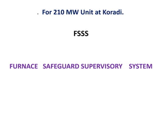
  • 1. FSSS FURNACE SAFEGUARD SUPERVISORY SYSTEM . For 210 MW Unit at Koradi.
  • 2. FSSS SYSTEM • 1. CLASS ROOM SESSION– UNDERSTANDING BASIC CONCEPTS & LOGICS OF FUEL FIRING. • 2. SITE VISIT- PRACTICAL IMPLEMENTATION OF THE SYSTEM. FUEL FIRING EQUIPMENTS,CONTROL DESK (operation of equipments), RELAY PANELS,ALARM & INDICATION .
  • 3. FURNACE • 1. CONSTRUCTION • 2.OPERATION • 3.MAINTENANCE • 4.INTERLOCK & PROTECTION- (LOGICS & CONCEPTS.)
  • 4. Furnace associated terminologies a. Hanging Structure. b. Elevation- AB,CD,EF & Corner- 1,2,3,4. c. Wind box-A/B. d. Scanner fans- Auxiliary Dampers e. Burner Tilt- 13 Compartments. f. Tangential fuel firing system- Fire ball at the centre g. Igniters- h. Fuel System- FO, LDO, Oil guns, Hydro motor valves. Instrument air & Service air system i. Soot blowing system.
  • 5. BOILER • CONSTRUCTION- Mechanical • AUXILLIARIES Associated with – ( Interlocks & Protections of auxiliaries) • OPERATION & Control of Boiler. • FUEL FIRING SYSTEM- Equipments & Control system-(FSSS)
  • 6. FUEL FIRING EQUIPMENTS- • MECHANICAL EQUIPMENTS & THEIR CONSTRUCTION • CONCEPTS & LOGICS INVOLVED IN FUEL FIRING SYSTEM • INTERLOCKS & PROTECTIONS INVOLVED • SEQUENCE OF OPERATING FUEL SYSTEM.
  • 7. EFFECTIVE FUEL FIRING– MEANS PROPER COMBUSTION • FURNACE HAZARDS- EXPLOSION -- IMPLOSION • NFPA 85-The National Fire Protection Association (NFPA) codes, such as NFPA 85: Boiler and Combustion Systems Hazards Code are dedicated to fire and furnace explosion and implosion protection
  • 8. • For proper combustion of fuel in the furnace , adequate supply of air must be supplied and intimately mixed with a supply of combustible material ( FUEL ) which has been presented in the correct condition. • HOW TO AVOID? • Boiler Furnace explosion may be avoided by timely purging and stoppage of leakage of fuel oil in furnace.
  • 9. Practical means of avoiding furnace explosion is the prevention of an explosive accumulation • Furnace explosion is rare, but very severe in nature. This situation exists because furnace is supplied with explosive accumulation. • Just a minute part of those explosive charges receive sufficient ignition energy to actually cause an explosion. • The Furnace explosion requires both sufficient explosive accumulation and sufficient energy for ignition
  • 10. CAUSE OF EXPLOSION- FURNACE PRESSURE- • Why to maintain furnace pressure ? • Furnace Pressure is one such very important parameter, which needs continuous control, protection & monitoring. This is very important from safety of the boiler. • In case of very low and very high pressure, the furnace may subject to explosion and implosion, which may result in Boiler Structure and pressure parts, tubes damage and furnace deformation. • Explosion Factor = (Mass/Furnace Volume) x Composition Change/Elapsed Time)
  • 11. The furnace explosion occurs due to: a) Improper purging of the furnace and air. b) Inadequate ignition procedures. c) Maintaining fuel supply for too long a period without establishing combustion. d) Re-lighting burners too soon after previous flame out. e) Introduction of main fuel without ensuring adequate ignition energy.
  • 12. FURNACE IMPLOSION • CONDITIONS UNDER WHICH FURNACE IMPLOSION WILL OCCUR- • 1)Boilers with both induced and forced draft fans may become unbalanced especially if the forced draft unit becomes tripped and the induced fan unit remains in full operation. • The induced draft fan will produce an excessive draft in the furnace and create the real likelihood of furnace implosion. • Negative pressure excursion of sufficient magnitude to cause structural damage. • Incase of ID Fan is capable of producing more suction head than the boiler structure is capable of withstanding. • Control malfunction and / or operator error, establish such conditions.
  • 13. • 2) The other process called flame collapse or flameout effect. The negative pressure excursion following a fuel trip and loss of furnace flame, in order to realistically evaluate pit falls and prevention techniques
  • 14. CONDITIONS FOR PROPER COMBUTION OF FUEL • It is the purpose of the burner to present the fuel in suitable condition for proper combustion. • Generally this means atomizing the fuel and giving it some axial (for penetration) and angular (for mixing) velocity. • For effective atomization the viscosity of the fuel is critical. • For fuels heavier than gas or diesel oils some degree of heating is required. • It should be noted that the temperature of the fuel should not be allowed to raise too high as this can not only cause problem with fuel booster pumps but also can cause flame instability due to premature excessive gasification. • The smaller the droplet size the greater the surface areas/volume ratio is, this increases evaporation, heating and combustion rate.
  • 15. DIAGRAM OF HOW THE FUEL BURNS INSIDE THE FURNACE?
  • 16. TYPE OF FUEL- LDO (LIGHT DIESEL OIL ) FO (FURNACE OIL ) PULVARISED COAL Equipments involved- 1.IGNITOR- TRIP VALVES, HEA IGNOTOR ASSEMBLY- SPARK ROD * SPARK TIP EXCITATION TRANSFORMER. & CKT. IGNITOR AIR FANS- FOR PROVIDING COOLING AIR TO IGNITOR TIP
  • 17. 2.OIL GUNS- • TRIP VALVES- OIL HYDROMOTOR VALVES- PNEUMATIC VALVES • ATOMISING VALVES- STEAM & AIR • SCAVENGE VALVES-
  • 18. 3.PULVARISED COAL- – COAL MILL- Ignition Energy availability condition. – COAL FEEDER- To regulate amount of coal input in the Furnace. – HAG & COLD AIR DAMPER
  • 19. 4.AIR SYSTEM- 13 COMPARMENTS • WINDBOX TO FURNACE DIFFERENTIAL PRESSURE MONITORING. • AUXILLIARY AIR DAMPERS- Modulating to control AIR flow
  • 20. 5.FLAME MONITORING SYSTEM- • BURNER TILTS- To maintain temp.& Keep fire ball at centre. SCANNERS- Flame scanners used to sense flame in boiler to detect flame failure to avoid boiler furnace Explosion. Flame Scanners & Fire ball scanners.
  • 21. 6.SCANNER System- • SCANNER LOGIC- • IGNITION ENERGY • FLAME FAILURE TRIPPING
  • 23. How the Fuel is Fired in Furnace?
  • 25.
  • 26. FSSS System— Furnace safeguard supervisory system This system supervises the Furnace operations, controls process parameters & Protects the Furnace under abnormal operating conditions. The functions of FSSS mainly include: 1. To Safe guard the Furnace against “Abnormal operating conditions.” 2. To Supervise the condition of furnace during fuel firing .
  • 27. INTRODUCTION Furnace safeguard supervisory system popularly called FSSS continuously monitors the operations related to fuel admission and some other vital parameters to ensure safety of the Boiler. Generally furnace oil or any kind of fuel is susceptible to explosion hazards. Majority of explosion occurs during start up, shut down and low load operations. There are many steps that must be followed by the operator to admit a fuel in to the furnace safely and properly. In high capacity boilers, where fuel input rate is very high major furnace explosions can result from the ignition of un-burnt fuel accumulated in the first one or two seconds. Human reaction time to such situations is inadequate. So there a proper burner management system called as FSSS is installed in the Boilers. Every operation related to fuel admission is accomplished through FSSS
  • 28. Advantages of FSSS system – a. Continuously monitors the operations related to fuel admission & vital parameters, to ensure safety of boiler. b. Every fuel is susceptible to Explosion hazards. Majority of explosions occurs during start-up, plan Shut-down, & Low load conditions. c. Boiler operator has to take many important & sequential steps to admit fuel in the furnace, safely & properly . If it is left to the judgment of the operator, then high probability of error will be involved. This system helps to reduce the error. D Accuracy of Ignition energy is an important factor for proper combustion of fuel. E System logics allows / Dis allows fuel admission in the furnace by monitoring furnace condition.
  • 29. FSSS Helps us to provide:---  Monitoring OF processes parameter  Control & Protection OF processes parameter whenever IT deviates from its normal value. System logics senses dangerous situations & does not allow Fuel admission in such situations & thus protects the furnace, if reqd, by giving trip commands to boiler. What is meant by Boiler trip ???  Every type of Fuel is cut-off from the Furnace .  NO Flame condition is established..
  • 30. FSSS System consists of -- Hardware & Software. Hardware  Panels in control room - Consists of Relays, Timers.  Control Desk-- -For operation of fuel firing equipments. (For Monitoring & Control of parameters )  Indication & Alarm system.— For alertness & actions.
  • 31. UNIT PANEL- 1 UNIT PANEL-2 AB Elevation CD Elevation EF Elevation Coal mill “A” Coal mill “B” Coal mill “C” Coal mill “D” Coal mill “E & F” FSSS Panels lay-out :- (For Relay based system )
  • 32. Software--  Electrical drawings- (Logic Diagrams. )  Supply system---220 V DC & 110 V AC 1) 110 v ac FROM IPDB ( Instrument panel distribution board.) used for relay logic system. 2) 220 V DC FROM DCDB ( DC distribution board), for relay logics & “TRIPPING Logic”. 3) 24 V DC for Indication supply. (Console indications)
  • 33. What are the Abnormal operating conditions ?  Flame failure,  Furnace pressure inadequate-High / Low.  Loss of fuel.  Air flow less than 30%.  Sudden tube leakage.
  • 34. What needs to be Monitored during fuel firing ?  Flame condition monitoring by flame scanners.  Total air flow monitoring.  Furnace pressure.( Negative )  Secondary Air flow ( Wind box to Furnace DP )  Oil pressure & Feeder speed.  Oxygen % in flue gas.  Drum level  Feed flow & Steam flow.
  • 35. Which are the Auxiliary system associated with Furnace?  Air flow system. ( Primary & Secondary )  Oil flow system :- (Light oil & Heavy oil )  Coal feeding system.  Feed Water system. Any Negative Impact on these systems will affect the working of Furnace.
  • 36. Interlocks & Protections are provided for safe working- What is meant by Interlocks & Protections ?
  • 37. 1. Air flow system. ( Primary & Secondary ):-  PA fans are used to provide primary air.  Hot air takes coal as fuel from mill to furnace at all the elevations. This requires sufficient Header Pr.  If the Header pr. Drops to certain level ,then we need to trip lower mills. Reasons for pr. Drop will be confirmed, corrective actions will be taken to restore the header pr. to normal value. If it is due to tripping of PA Fans , then it will be difficult to run furnace. So Boiler will be tripped.
  • 38. FD Fans are used to provide secondary air.  This air is used to help complete combustion of fuel.& maintain Tangential Firing ,to keep fire ball at the centre.  DP is maintained between Windbox to Furnace.  Secondary air also helps to maintain Furnace Draft. If FD Fan trips ,due to any reason,then interlock is provided to trip corresponding ID Fan.  This air is also used to cool scanners through scanner fans.
  • 39. 2. Oil flow system :- (Light oil & Heavy oil ) Light oil is used during initial light-up of furnace, to bring Sufficient ignition temp.for firing Heavy oil. “Light oil fuel flow” &” Temp adequate” are the required conditions, used as interlocks.  Heavy oil is used, to bring Sufficient ignition temp. for firing Coal .Naturally Heavy oil Temp adequate” is the required condition, used as interlock. Four guns are used at each elevation. When-ever ¾ guns are working properly,Ignition permit is given to fire coal as fuel, as it brings the ignition temp. for coal to burn completely.
  • 40. 3. Coal feeding system.:- •Pulvariser ready condition is reqd. Conditions reqd for Pulvariser ready:- Pulv. Outlet temp not high, cold air valve open. Tramp iron valve open, seal air valve open. feeder start permissive, NO PA trip, NO pulv.stop. Pulv. discharge valve open.
  • 41.  Hot air gate to be open. ( Proper opening of hot & cold air dampers ) •Coal feeder need to start. • Feeder speed to raised as per requirement of load.
  • 42. 4. Feed Water system. :-  Low load line valves operative.  Main line valves operative  ELP & BFP ready to start.  Drum level auto control healthy.  Drum level Protection in service.
  • 43. PURGE READY INTERLOCK FOR BOILER:- CONDITIONS REQD.:- All Heavy /Light oil valve closed. Flame scanners indicate NO Flame All feeders off/ All pulverisers off. No boiler trip All HAG closed All aux.dampers modulating.
  • 44. Major FSSS INTERLOCKS:- •Elevation load < 30 %. •Loss of AC at any elevation in service. •Loss of DC Supply for > 2 secs. { unit trips while restoring the DC supply. ) •Heavy oil temp. adequate. •Burner tilt horizontal •Air flow less than 40 %. •Drum level high / low. •ID /FD fan off.
  • 45. Heavy oil supply pressure adequate. Limit switch contact for Trip valve open. LDO fuel supply pressure adequate. LDO header pressure low.  Atomising air / Steam pressure low. .Aux. air dampers modulating.  Scanner fan ON .HOTV valve open  PA pressure low
  • 46. FD / PA trip.  Pulv / Feeder ON  Seal air valve open  Pulv.outlet temp high. Hot air gate open.  Scanners show FLAME  OIL valve open,Atomising valve open.
  • 47. S.N. Boiler Trippings Effects. 1 Drum level very high. To prevent Entry of wet steam in Turbine, 2. Drum level very low. To avoid boiler starvation 3 Furnace draft inadequate (V.High /V. low ) To safeguard furnace from excessive stresses. 4 Total air flow & boiler load less than 30 %. To ensure sufficient air for combustion during start up activity. 5 Flame failure trip To avoid admission of coal when sufficient ignition energy is not available. Boiler protections :-
  • 48. Flame failure trip To avoid admission of coal when sufficient ignition energy is not available. Loss of all fuel trip. To ensure re-admission of fuel only after furnace is Purged. Both ID trips. No means of driving out flue gases to avoid operation of furnace in such situations. Both FD trips. No supply of air for combustion. Loss of supply to FSSS logic system To prevent boiler operation ,if safeguard system is not functioning.
  • 49. Mannual trip Push buttons pressed. For manual trip when-ever reqd. Turbine trip Interlock tripping. Furnace temp. very high Excessive heating of reheater tubes.May cause tube failure. Implosion damper open To prevent development of excessive – ve pressure in the furnace.
  • 50. FUEL FIRING ACTIVITY START & STOP. (LIGHT UP & WITHDRAWAL OF UNIT) FIRE KILLING OPERATION- UNIT WITHDRAWAL ACTIVITIES
  • 51. WHICH ARE LIGHT UP ACTIVITIES ? PURGING,- Purging is done to clean furnace from combustible gases by running ID Fan and FD Fan at atleast 30% load for 5 minutes to avoid Furnace explosion. OPENING OF TRIP VALVES, MONITORING OF OIL PRESSURE & ,FLOW, ATOMISING MEDIUM HEADER PRESSURE. AUXILLIARY AIR CONTROL SYSTEM, WIND BOX TO FURNACEDIFFERENTIAL PRESSURE.. Firing of ignitors Taking of LDO oil guns- OPENING OF OIL VALVES,ATOMISING VALVES.,
  • 52. CHECKING STABILITY OF FLAME SCANNERS. MONITORING FURNACE TEMP, PROVING HIGHER ELEVATION OIL GUNS. DEVELOPING REQUIRED DRUM PRESSURE FOR ROLLING PURPOSE. COAL MILLS,COAL FEEDERS,HAG & DAMPERS CONTROLS
  • 53. Light up Activities Preparedness FURNACEPURGE:- Furnace purge is required after a boiler trip out, before relighting the boiler to expel all unburnt full particles, vapor etc, form the boiler so that when spark is introduced during light up, possibility of explosion are avoided.
  • 54. FSSS ensure a proper furnace purge in following manner:- “Purge Ready” signal when appear only when following conditions are fulfilled. 110V AC and 220V DC supply to FSSS panel is switch on.  Boiler Drum water level normal.  At least one ID and one FD fan running.  Establish 30% full load air flow as seen in total air flow recorder.  Igniter trip valve closed.  Warm up trip valve closed.  Heavy oil trip valve closed.  All igniter valves closed.  All warm up and oil gun valve closed.
  • 55. All auxiliary air damper modulating to maintain air flow can adequate wind box to furnace differential processing?  All coal mills off.  All raw coal feeders off.  All flame scanners show no flame.  All mill hot air gates closed and cold air damper are less than 5 degree open.  No boiler trip command. When above conditions are met, signal “purge ready” will disappear, even during purging process. When signal “purge ready” appears, press button “push to purge after the expiry of purging time signal “purge complete” appears.
  • 56. LIGHTING UP WARMUP ELEVATION Now we are ready for Boiler light up. a) Lighting up warm up elevation AB Elevation AB has capability to be used for either burning light oil or heavy oil. So select “light oil” on the consol for AB elevation ensure warm up oil tips are provided is guns of that particular elevation. b) I] Igniter trip valve: Press igniter trip valve “open” push button igniter trip valve oil open provided the following condition are fulfilled. Igniter oil supply pressure adequate (more than 12.1 kg/cm2) All igniter valves closed. No boiler trip command. In addition, instrument air supply must be available to actuate trip valve. If igniter fan is not started, it will start when first igniter start Command is given.
  • 57. II] Opening light oil trip valve: Light oil trip valve will open if following condition is met:  No boiler trip.  Elevation AB LO valves on guns is closed. Light oil pressure adequate i.e. they should not less than 1.4 kg/cm2 for more than 25 sec. and light oil trip valve open push button pressed. The following figure shows logic diagram for “warm up oil trip valve control”. Before Boiler light up with Light Diesel oil, LOTV must be open by giving “open” command from push button switch on the desk. Output form “OPEN” push button switch goes to an AND gate. Other input to this gate are_ 1. No Boiler Trip 2. All Corner Valves closed 3. LDO Pressure Adequate 4. LOTV “Close” command not persisting When all these inputs are TRUE, OPEN command causes AND gate to give a TRUE output causing LOTV to open.
  • 58. LOTV closes when Close command through push button switch is initiated OR Boiler trips OR After a delay of 3 second when any warm up oil elevation’s Corner valve is NOT CLOSE AND If LDO Pressure drops to LOW valve OR If P between atomizing air and LDO is low.
  • 59. Starting Igniter: When igniter is started for 1st 10 sec period, oil and atomizing air are admitted though the valve and simultaneously a spark is applied. The spark lights up the oil spray and flame is sensed by flame sensor in the igniter. This happen within 10 secs, the valve is held ‘open’ allowing igniter to continue. There are no separate igniter start push buttons, pressuring any one pair of oil gun start or stop push button will give starting impulse to all four igniter of that elevation. To start the oil guns press either 1and 3 or 2 and 4 start button. This gives commands for igniter start provided the following condition is met:  DC power available.  No boiler trip command.  Burner tilt horizontal and air flow less than 40%.  Igniter trip valve open.  L.O. trip valve are open. Igniter start causes following gives a start command to spark plug. This command holds for 10 secs by which time if flame is in the igniters. Now in this way at least three igniters on selected elevations are proved command is given for selected LO guns to advance and light up provided:
  • 60. oAtomizing air valve open o Warm up oil valve open. o Corresponding igniter proved. Under this condition, first one gun will advance, atomizing air will open the next gun of will undergo similar operation with time log off 25 secs in this at least three guns have to be proved, otherwise oil guns will trip out. When guns trips , the gun will not retract , it must be retracted locally immediately to avoid any fire accident. Warm up guns will trip under following conditions:  Pressing stop push button.  Moving local switch from ‘Remote’ to any other position.  Gun advanced or engaged limit switches are released.  Corresponding igniters trip out.  Air or oil is elevating valve are closed.  Oil valve is not proven to be open within 90seconds.  Any boiler trip command.  At any time when warm up guns are in service, it more than one igniter is off all warm up guns oil trip.
  • 61. LIGHTINGUP HEAVY OIL ELEVATION I] Lighting up Heavy Oil Elevation. Healy oil can be fired on any three elevation AB,CD and EF. Heavy oil guns are supposed to be self sustaining. Once three oil guns are tilt, their flow (gun loading in that particular elevation) is more than 30% or Boiler load more than 30% and flame scanners are sensing flame under these condition light oil can be withdrawn without affecting oil guns. II] Now the heavy oil valves open under following condition are met.  Header oil pressure adequate.  All heavy oil hydra motor valve of AB, CD, EF oil guns are proven closed.  No boiler trip command.  Heavy oil pressure not low less than 1.4 kg/cm2 for more than 2 secs.
  • 62. When valve open signals open appears on the panel. Starting igniter command oil materialize only when heavy oil is ready for light up with oil temperature more than 1050C . Now taking heavy oil guns service in elevation AB. Gun will advance provided:  Atomizing steam isolating valve open.  Heavy oil manual isolating valve open.  Heavy oil igniter on. Under this condition oil gun advance.
  • 63. When valve open signals open appears on the panel. Starting igniter command oil materialize only when heavy oil is ready for light up with oil temperature more than 1050C . Now taking heavy oil guns service in elevation AB. Gun will advance provided:  Atomizing steam isolating valve open.  Heavy oil manual isolating valve open.  Heavy oil igniter on. Under this condition oil gun advance.
  • 64. MILL FSSS controls the salve starting, running and stopping of mills. Pulverizer Ready for start This is common to all six mills signal Pulverizer ready will appear when all the following conditions are fulfilled.  Mills outlet temperature is less than 900C.  Seal air valve open.  Cold air gate open.  Feeder inlet gate open.  Pulverizer discharge valve open.  Tramp iron hopper gate open.  No Pulverizer trip command.  Burner tilt horizontal and air flow less than 40% for subsequent mills, the first R.C. feeder ON. Energizes relay by passing burner tilt and air flow conditions.
  • 65. Ignition permissive : It is presumed that P.A. fan is running, seal air fan is running, P.A. header pressure is normal before we can actually start the mill, another conditions that of providing sufficient ignition energy near the burner nozzle of the mill has to be ensured so that, once coal flow is established through mill, the pulverized coal will light up inside the boiler without any loss of time. At least three oil guns (Heavy oil or warm up) are in service for the first mill to be started A or B, C or D, E or F. For second mill to be start ignition energy is given by either:-  Three oil Guns being in service adjacent to mill or  Boiler load is more than 30%.  Adjacent mill running with RC feeder speed in excess of 5rpm or Pulverizer A or C in service at igniter than 50% loading.  This ignition energy must be continuously available for three minutes after starting RC feeder. Even though the logic permits removal of ignition energy after three minutes operationally it will be required for even longer period till boiler flame conditions are stable.
  • 66. The following figure shows Logic Diagram for Ignition Permissive for Pulverizer A and B. Similar requirements are applicable for other Pulverizers: 1. Pulverizer B is running with 50% loading AND Boiler Load is More than 30% OR a) Elevation AB in service with 3 out of 4 Guns established. 2. Pulverizer B Ignition Permissive is available if a) Pulverizer A or C running at 50% loading AND Boiler load is more than 30% OR b) Oil Elevation AB in service with 3 out of 4 Guns established.
  • 67. Actual starting of the mill If conditions are met and if local key release push button is released mill can be started by pressing the start push button on console.  As soon as mill starts, cold air damper opens full.  Hot air gate can now be opened provided temperature after mill still remains less than 900C. If the temperature exceeds 900C, the white signal ‘ Pulverizer ready’ will disappear but the mill will continue to run. Pulverizer ready can disappear for other reason also. However if discharge damper closes mill will trip immediately.  After opening the hot air gate, cold air and hot air damper can be regulated to achieve an after mill temperature of 600C to750C and P.A. fan flow about 52 T/hrs. During manipulation of air, take care load P.A. fan so, that P.A. header pressure does not fall below 650mm.  If the ignition energy continuous to be present after starting mill, feeder can be started and mill loaded.  As soon as feeder is started, signal given to panel to modulate fuel air accelerator to speed of feeder. When feeder stops, fuel air damper is shut. This is to facilitate quick light up of fuel when a mill is started.
  • 68.  After 50 seconds of feeder starting relay energizes to permit feeder to be controlled by boiler pressure auto. PULVERIZER START When ignition energy available and Pulverizer ready condition are establish for the respective Pulverizer. The Pulverizer may be place in service as follows: a) Start the Pulverizer by pressing start push button b) When Pulverizer is proven on as indicated by its on indication or by amp on UCR open, hot air gate and allow pulverize to come adequate temp (750C) and PA flow of about 52 T/hr with the help of cold air damper. c) When Pulverizer is up to temp 1400C start feeder and set at minimum and associated elevation of fuel air damper proven close. Coal flow must be proven either by coal flow detector or satisfactory Pulverizer amp within 5 secs after feeder started. When minimum of the two feeders are establish at greater than 50% loading, associated elevation of oil guns may be shutdown provided feeder has been on for minimum 3 of 3 minute.
  • 69. FAN CONTROL Igniter and scanner fans: Igniter fan:- Igniter can be started from control desk otherwise it get set started automatically when any igniter or oil elevation start is initiate at least one ID and more than one FD fan must be service for the igniter fan to start on stopping igniter fan from control desk will remove the associated igniter fan service provided all of igniter valve are closed. Scanner Fan Control:- It can be started from control desk otherwise it get started automatically when the scanner air duct to differential pressure falls below 4.5”w.g. low differential pressure more than 10 secs will alarm, the scanner emergence damper open on interlock when both ID/FD fan are off, this allows the fan to draw ambient air for the cooling scanner when unit is bottled up on stopping fan from control desk will remove the scanner fan from service provided the scanner duct to furnace desk. Pressure is above 4.5”w.g.
  • 70. CONTROLof THE WIND BOX DAMPERS 1] Auxiliary Air Dampers: During furnace purge and when load is less than 30%. FSSS modulates are auxiliary air dampers to maintain a low wind box pressure (30mm). When load increases beyond 30% the modulation is for a higher wind box pressure (60mm), which is achieve by closing dampers near elevation not in service. When warm up oil is in service, the auxiliary air damper of AB elevation opens to a predetermined position. When heavy oil is in service, the auxiliary air is allowed to be controlled by opening depending on oil pressure. When one FD fan trips, then all auxiliary and fuel air damper open wide. 2] Fuel air dampers: All the air dampers are shut on elevations where there are no feeders in service. After starting of feeder, the fuel air damper of that elevation is allowed to be controlled with feeder speed.
  • 72. SUMMARY: FSSS achieves---  Smooth boiler start –up.  Routine operations.  Withdrawal of boiler safely,when ever reqd.  Tripping in case of abnormal conditions.
  • 73. HOMEWORK: INTERLOCKS & PROTECTIONS– ID-FD-PA-BFP AUXILLIARY INTERLOCK PROTECTION ID FAN Over current,Earth fault,Shot circuit,Locked Rotor,DifferentialFD FAN PA FAN BFP