1. TOWARDS MECHANISTIC BEHAVIOUR OF FLEXIBLE ROAD
SURFACING SEALS USING A PROTOTYPE FEM MODEL
T.I. Milne1, M. Huurman2, M.F.C. van de Ven2, K.J. Jenkins3, A. Scarpas2 and
C. Kasbergen2
1
Africon
PO Box 11126, Hatfield, 0028, South Africa. Tel: (012) 4273051. Fax: (012) 4273050.
E-mail: tmilne@africon.co.za
2
Faculty of Civil Engineering and Geosciences, Delft University of Technology
PO Box 5048, 2600 GA, Delft, The Netherlands. Tel: (0931) 15 27 81525.
E-mail: m.huurman@citg.tudelft.nl, M.vandeVen@citg.tudelft.nl, a.scarpas@citg.tudelftc
and kasbergen@citg.tudelft
3
SANRAL
Chair in Pavement Design, University of Stellenbosch. Tel: (021) 808 4379.
E-mail: kjenkins@ing.sun.ac.za
ABSTRACT
In many countries with sparsely populated areas, or countries with developing economies where
resources are at a premium, road surfacing seals are widely used to provide a durable, all
weather pavement surfacing. However, with the changes in global oil sources, weather patterns
and traffic loading and contact stresses, a need has been identified to re-examine the methods
with which road surfacing seals are designed. Current road surfacing seal design practice
utilises empirical methods, based on historic experience, and volumetric based assessment of
bitumen binder application.
This paper investigates South African seal design areas where review or updating is suggested.
Seal performance criteria are examined, and the need for a seal design method based on
mechanistic principles is proposed. A prototype seal behavioural model initiating the
development of a mechanistic design tool for seals and thin surfacing layers was developed
using Finite Element Method (FEM). The potential benefits to practice of the mechanistic design
tool will be enhanced as the design model is developed, and initial contributions to practice,
such as enhancing the understanding of the behaviour of seal components, are discussed, with
the demonstration of the first multiple element seal FEM model.
1. INTRODUCTION
Bitumen and asphalt have been used by society’s Engineers “to counter the damage to the
existing unsurfaced roadways by the newly developed automobile with its rubber driving wheels”
since the early 1900s (Hoiberg, 1964). Early experiments were conducted with both tar and
bitumen to find a suitable material to alleviate the situation, and ongoing research has been
carried out through the past century and into the new millennium, throughout the world,
including examining improvements, from materials used, to design and construction methods.
However, there is still much to be understood, improved and refined, illustrated by the editors to
the proceedings of the symposium on “Polymer Modified Asphalt Binders” (Wardlaw, Schindler,
1992) (and still a pertinent comment) that “the current asphalt binder being supplied has not, in
many areas, performed as expected…”.
Pavement designers have the choice of utilizing either an asphalt (graded aggregate
pre-manufactured with a bitumen binder and applied as a complete product) or a surfacing seal
Proceedings of the 8th Conference on Asphalt Pavements for Southern Africa (CAPSA'04) 12 – 16 September 2004
ISBN Number: 1-920-01718-6 Sun City, South Africa
Proceedings produced by: Document Transformation Technologies cc
2. 8th CONFERENCE ON ASPHALT PAVEMENTS FOR SOUTHERN AFRICA
(bitumen binder sprayed onto the road surface, with the addition of single size stones, either in
one or two layers of binder and aggregate, i.e. single or double seal). The various seal types are
reflected in Figure 1.
Current road surfacing seal design practice depends on empirical modelling and experience.
With the modern trend of increased traffic loading and contact stresses, varying oil sources and
related refining processes and by-products, it is postulated that current seal design assumptions
and practice are not directly applicable to the changing situation, and require re-examination
(Milne, 2004).
This paper examines design and prediction aspects of the Single Seal used for road surfacings.
Performance criteria for a seal evaluation model are proposed, and the development of a
prototype Mechanistic Behavioural Model of Flexible Road Surfacing Seals using FEM Methods
is provided.
(Note: Open seal (no stone contact) in Numerical Modelling to allow study of binder in prototype)
Figure 1. Seal types (CSRA, 1998).
2. SOUTH AFRICAN SEAL DESIGN PRACTICE
Current South African seal design methodology is presented in the Technical Recommendations
for Highways 3, usually referred to as “TRH3” (CSRA, 1997 & 1998). This methodology is based
on Hanson’s concept first tabled in the 1930's of partially filling the voids in seal aggregate, and
that the volume of voids in the aggregate layer is controlled by the Average Least Dimension
(ALD) of the aggregate. Climate, binder type, traffic and existing surface all have an influence
Paper 004
3. 8th CONFERENCE ON ASPHALT PAVEMENTS FOR SOUTHERN AFRICA
on the desired application rates for the seal bitumen binder. The current revised TRH3 (1998
Draft) includes the following enhancements on the Hanson model (CSRA, 1998):
• Minimum void space to be filled to retain the aggregate is 42 per cent for single seal, 55 per
cent for double seals (if no embedment is to be accommodated).
• Void loss under traffic, due to wear of the aggregate, is dependant on aggregate hardness.
• Required minimum texture depth for adequate skid resistance is 0,64 – 0,7 mm.
• Embedment under construction is assumed to be 50 per cent of total lifetime embedment.
Further assumptions regarding the use of modified binders include:
• All embedment occurs under construction and that further embedment under traffic is
reduced due to the elastic “mat behaviour” of the modified binder.
• Due to the higher binder viscosity, the seal stones do not lie on average least dimension
(ALD), but lie as they land in the bitumen, with increased voids being available, allowing
higher binder application.
• The higher viscous behaviour of the modified binders is accommodated in the design
through the use of “binder adjustment factors” based on “ring and ball” softening point
(CSRA, 1986), to make provision for stone orientation.
The traffic loading is measured in “equivalent light vehicles (elv’s)” per lane, where heavy
vehicles are converted to equivalent light vehicles using assumed “equivalency factors”
(currently one heavy vehicle to 40 elv’s) (CSRA, 1998).
The design process provides binder and aggregate applications based on the empirical design
curves, with input in terms of ALD, stone hardness, and existing surface texture depth and
hardness, and equivalent traffic.
It is evident that the current seal design method is not able to take cognisance of:
• Varying axle loads, tyre contact stresses and design speed.
• Varying characteristics of the different binders (i.e. temperature – viscosity relationships,
adhesion and visco-elastic behaviour).
• Varying service environments or micro-climates.
The major areas identified for suggested improvement in current seal design methods are:
• Inclusion of variable service environment characteristics, including traffic load, service road
and temperature and moisture influences.
• Inclusion of material behavioural characteristics into the design methodology, especially
regarding:
- Bitumen behaviour and characteristics.
- Existing base/asphalt wearing course behaviour.
3. SEAL PERFORMANCE CRITERIA
Seal performance criteria have been defined as avoidance of certain failure parameters
(Roberson et al, c.1990), these being:
• Permanent deformation (punching, rotation of seal stone reducing voids)
Paper 004
4. 8th CONFERENCE ON ASPHALT PAVEMENTS FOR SOUTHERN AFRICA
• Early rutting of the supporting base
• Fatigue cracking
• Low temperature cracking
• Moisture damage
• Adhesion failure
Empirical research (Milne, 2004) has demonstrated that the life of a seal is dependant on the
performance of the base regarding:
• Permanent base deformation: punching (associated with bleeding) and rutting
• Moisture damage to the base
and dependant on the seal material behavioural components for:
• Permanent deformation or loss of texture: rotation of seal stone, reducing voids (associated
with bleeding), failure of “mat” behaviour allowing punching
• Fatigue cracking (postulated due to brittleness of ageing seal)
• Low temperature cracking
• Adhesion failure (stripping)
• Aggregate crushing or polishing
The failure parameters thus applicable to the modelling of a road surfacing seal (as opposed to
the parameters applicable to the modelling of the structural layers) will be:
• Deformation and texture loss: rotation and punching of seal stone
• Cracking: fatigue (ageing of binder and loss of elasticity)
• Low temperature brittleness
• Loss of adhesion (of stone to bitumen, and bitumen to base)
• Aggregate (crushing or polishing)
In terms of performance evaluation it is usual to describe performance measured against failure
criteria. However when considering the role of the surfacing seal – the protection of the
pavement layers from abrasion and the elements, and the provision of a safe riding surface –
the question of sufficient time to failure must be considered. The time to failure could be defined
as the time to pavement failure, OR the time to reseal. This follows from the consideration that a
pavement’s serviceable life is determined by construction quality, traffic load, environment,
substrate, pavement type, and many other factors (with seals there is also the possibility of
single event catastrophic failure, such as cold weather stipping or hot weather binder flow).
The factors that influence seal behaviour (Marais, 1979) are reflected in Figure 2 with their
influence on seal behaviour, with the criteria determined for the seal performance evaluation.
Paper 004
5. 8th CONFERENCE ON ASPHALT PAVEMENTS FOR SOUTHERN AFRICA
Figure 2. Seal performance criteria (Milne, 2004).
4. IDENTIFIED NEED FOR SEAL MODELLING THE SEAL BEHAVIOUR
Design methods for prediction of structural pavement elements’ lifetimes, and assessment of
requirements for design traffic loads, are increasingly based on mechanistic design methods
(methods based on principles of mechanics such as elasticity, plasticity, visco-elasticity), rather
than empirical methods (based on experience or index properties – such as CBR, limiting
deflections, etc.) (Desai, 2002). There is currently no available tool to assess the above
performance parameters in service for different seals (Huurman et al, 2003), nor is there an
analytical tool available to differentiate between the performance of different seals under
different environments and loading. There is thus a need for the further examination and
evaluation of seal performance in terms of the performance criteria through an analytical tool
(numerical behavioural model), to complement the current available design methods and the
performance based evaluation method (Milne et al, 2002).
The modelling of road surfacing seals using mechanistic principles with determined failure and
fatigue criteria or relationships would enable assessment of the seal expected lifetime, inclusion
of different component material characteristics and variations, varying traffic and environmental
conditions. It was with the above in consideration, that the feasibility of the development of a
performance behavioural model for seal design and assessment was examined, using specific
finite element analysis tools.
From assessment of literature, and understanding of the components of the seal and pavement,
and influencing factors, a choice of numerical model of seal performance was made.
The Finite Element Method (FEM) Analysis was selected for the purpose of modelling seal
performance for the following main reasons:
• The seal components and geometry are too complex to use simple isotropic models.
• The ability of FEM to model complex stress analysis problems.
• Enabling the approximation of material characteristics by the collective behaviour of all the
elements (stress and strains are able to be determined in each of the elements from the
determined displacements using the applicable elastic and visco-elastic methods).
Paper 004
6. 8th CONFERENCE ON ASPHALT PAVEMENTS FOR SOUTHERN AFRICA
• The availability of proven existing modelling software.
In the above context, a prototype seal behavioural model was developed, using the influencing
factors to design the input for the model, and the performance criteria for assessment of the
seal behaviour under a determined service environment (temperature and traffic load).
5. DEVELOPMENT OF A SEAL BEHAVIOURAL MODEL
The development of the model from scratch is a process, with substantial new work required for
not only the fundamental basis of the model, but for refining the specific material parameters
required for ultimate calibration to enable accurate prediction of each specific seal’s
performance.
5.1 Model Parameters for Measurement of Seal Performance
Based on the seal performance criteria discussed above, the following parameters are
applicable to modelling the behaviour of a seal.
Table 1. Ultimate seal performance parameters for model behavioural evaluation.
Model Parameter Failure criteria Measurement
Component
Base Punching (associated with Texture depth below that Number of elv’s to texture
bleeding) required for desired skid depth < 0,64 mm (CSRA,
resistance 1998)
Seal Rotation to ALD Void reduction to that below Number of elv’s to volume of
(associated with bleeding) which texture depth not voids reduced to less than that
adequate required for texture depth
Seal Cracking: ageing fatigue Seal cracks under dynamic Performance curve for number
(loss of cohesion) load of elv’s to cracking, stress
determination at yield
(including fatigue relationship)
Seal Cracking: cold Seal cracks under load when Number of elv’s to yield stress
temperature brittleness tensile stress exceeds yield reached (including fatigue
(loss of cohesion) value (temperature dependant) relationship)
Seal Loss of adhesion: Seal stone dislodged under Number of elv’s to yield stress
stripping/ravelling wheel load being reached (including
fatigue relationship)
Seal Loss of adhesion: Bitumen comes into contact Number of elv’s to zero texture
bitumen pick-up with wheel (i.e. after punching, depth, yield stress on bitumen
rotation), adhesion with base adhesion
fails
Notes:
1. Bitumen material characteristics are temperature, time of loading and age dependant, which will have
to be accommodated in the modelling of fundamental material parameters.
2. Bitumen behaves in elastic, viscous and brittle manners, depending on time of loading and
temperature.
5.2 Model Components
The modelling of a seal must include (Milne, 2004):
• Seal stone;
• Bitumen;
• Base; and
• Applied traffic load and contact stresses.
The complexity of any seal model becomes evident when considering the fundamental material
parameters to describe the components and their interaction.
Paper 004
7. 8th CONFERENCE ON ASPHALT PAVEMENTS FOR SOUTHERN AFRICA
To this end, the prototype model focussed on the modelling of the seal components: stone and
binder, with traffic load and temperature, considerations. The model was designed in such a
manner that it can be placed onto a base, to allow further development towards the ultimate
performance behavioural model.
5.3 Philosophy of Model
The philosophy of the model evolved from consideration of the components of the seal, and
their interaction, utilising finite element methods as summarised below:
• Examination of the interaction at the level of individual components (stone and bitumen), i.e.
micro-mechanics.
• Generation of an element of a single stone and the related seal components, thereafter
multiplying the elements to generate a seal mat of adjacent seal elements (the individual
seal stone and bitumen surround).
• The seal foundation could be comprised of the base, modelled in two layers:
- Thin (soft) contact layer to allow embedment.
- Thick rigid (high stiffness compared with the bitumen) support layer.
• Load
- Time load functions simulating a FEM model "E80" equivalent heavy vehicle axle load.
• Interfaces
- Interface elements will be included between stone and bitumen, and between bitumen
and base.
- These interfaces will allow interaction (such as adhesion) to be modelled.
5.4 Parameterised Model
The setting-up of the FEM model occurs in two phases:
• The generation of the Mesh
To enable accommodation for changing stone size and binder application, distance between
stones, and other parameters, the mesh generation should follow the method of being
“parametised” (Huurman et al, 2003).
This is implemented using a mesh generating spreadsheet based system, where element
node coordinates are entered using formulae linked to the input parameters. In this manner
a model has been initiated that can include:
- Average least dimension (ALD) of the seal stone
- Aggregate (seal stone) nominal sizes
- Bitumen (binder) application rate
- Lateral and longitudinal distance between the seal stones
- Initial texture depth
• The finite element analysis
- This includes the input of material parameters.
- In the finite element analysis itself, the actual material parameters are entered, allowing
assessment of differing materials and environmental effects (on the temperature
dependant items) without influencing the mesh generation.
Paper 004
8. 8th CONFERENCE ON ASPHALT PAVEMENTS FOR SOUTHERN AFRICA
6. PROTOTYPE SEAL BEHAVIOUR MODEL
The original initiation of a 3-dimensional seal model was undertaken in 2002 at Technical
University Delft, using the CAPA research programme, and the TU Delft computer resources of
required computational ability. Work continued on the development of the CAPA components
(Collop et al, 2003) and seal model in 2003, resulting in the prototype seal model, of binder and
seal stone. This is the subject of this paper. Subsequently a base mesh has been developed
which is available for further development.
6.1 Prototype Seal Surfacing Model Mesh (Geometry)
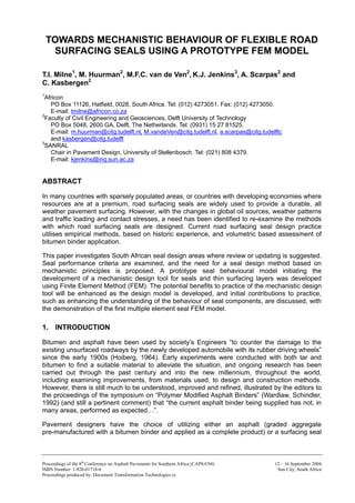
In Figure 3 the basic layout of the prototype model is presented. Various shades refer to
different materials. The model is made up of modules that consist of individual stones
encompassed by bitumen. By adding modules together, the model is compiled to a size that
allows assessment of central seal stone free of edge effects.
Figure 3. Basic layout of the FEM for seal surfacing with interface elements (“Round Stone”).
Given the importance of the adhesion between stone and binder, for both cracking and
stripping/ravelling damage, each stone is placed in a bowl of interface elements between the
stone and binder. These elements, also shown in Figure 3, will be used to model the bond
between stone and binder.
Stone shape and stone orientation is able to be randomised through the parameterised model.
The model-parameters may be used to alter the basic topology of the model:
• Average stone size in three directions (stone orientation);
• Number of stones per unit area;
• Thickness of the binder layer below the stones; and
• Volume of binder.
A random generator may be used to vary the above parameters per stone. Since stone shape is
also considered to be an influencing parameter, a random generator may also be used to affect
the stone shape. This random generator acts on the radius of the stone. Figure 4 shows the
effects of these random generators on the topology of the mesh, where the edges of the stones
are now irregular when compared with figure. 3. In this context, “smooth stones” refer to the
symmetric seal aggregate, as reflected in figure 3, and “rough” stones refer to the irregular
edged stones of the randomly generated mesh, as reflected in figure 4.
Paper 004
9. 8th CONFERENCE ON ASPHALT PAVEMENTS FOR SOUTHERN AFRICA
Figure 4. Mesh of the seal surfacing generated with the
use of random generators (“rough stone”).
The parameter input for the prototype mesh is provided in Table 2 below.
Table 2. Model parameter input.
The FEM seal stones are situated adjacent to the centre line, as reflected in Figure 5 below:
•
Figure 5. Relative position of FEM seal under tyre contact patch (not to scale)
(from Woodside et al, 1992).
6.2 Fem Material Parameters
6.2.1 Bitumen binder
From the literature review (Milne, 2004) and specifically Hagos (2002), the material parameters
for the bitumen have been determined for the prototype numerical model.
Paper 004
10. 8th CONFERENCE ON ASPHALT PAVEMENTS FOR SOUTHERN AFRICA
Of importance was the necessity to include parameters for:
• “straight” penetration grade bitumen
• modified bitumen
through the temperature ranges from brittle to viscous fluid, ie 10°C to 50°C.
Using Hagos’ parameters and the correcting factors provided, plus the Time Temperature
Supposition Principle (TTSP) (Hagos,2002), a full range of data was obtained for use in the
prototype model and future numerical modelling of the seal binders.
For the simulation of the straight binder, the results for the 70/100 pen grade bitumen was
selected. For the modelling of a modified binder, the 3 per cent SBS (linear) modified binder was
selected. The linear (L) rather than radial (R) SBS was selected with the Burgers model (Milne,
2004) (elastic spring and viscous dash pot) material simulation in the FEM program)
consideration. The temperature ranges considered were in line with the performance tests at
10ºC, 25ºC and 50ºC and the behavioural ranges of bitumen: brittle/stiff (± 10ºC), elastic
(± 25ºC) and viscous fluid (± 50ºC).
The Hagos (2002) Burgers model featured one Kelvin element and one Maxwell element in
parallel. Table 3 reflects the elastic and viscous parameters as used by the FEM model.
Table 3. Burgers model material parameters for prototype FEM model (milne, 2004).
With reference to the selected parameters, the spring stiffness of the binder remained constant
(reflecting the time of loading function, i.e. bitumen binder's elasticity under rapid loading), while
the dash pot viscosity showed order size reduction with increase in temperature. This reflects
the physical nature of bitumen.
6.2.2 Aggregate
The seal stone aggregate, when compared with the numerical model parameters, is very stiff.
The Young’s (E) Modulus for the stone was taken as 200 GPa (Milne, 2004)
The E-Modulus for aggregate is thus 103 order size greater than bitumen.
6.2.3 Interface
The CAPA FEM numerical model interface will be used ultimately to model adhesion,
amongst other parameters. The interface parameters are required in terms of stiffness, units
N/mm3.
For the prototype model, this was derived from dividing the assumed E-Modulus of the interface
by the interface thickness. Due to the interface numerical parameters still being the subject of
current research, the extremes of the interface stiffness was decided after discussion with the
CAPA group at TU Delft. The two extremes are:
• Using Ebitumen ÷ interface thickness
• Using Eaggregate ÷ interface thickness
Paper 004
11. 8th CONFERENCE ON ASPHALT PAVEMENTS FOR SOUTHERN AFRICA
The interface stiffness varied was the local “z” direction, i.e. stiffness perpendicular to the
contact surface. Interface stiffness thus ranged from 1 x 10³ N/mm3 (series Ebitumen/Interface IF
thickness) to 1 x 10⁶ N/mm3 (Eaggregate/Interface IF thickness) (Units are a stiffness / a thickness)
(Milne, 2004).
The local x and y interface stiffness are kept 102 order size higher than the z parameter (z on
local axes parallel to the applied load) to reduce resulting deformation in these directions, to
enable the effect of one variable (i.e. the stiffness) to be examined.
6.3 Numerical Model Applied Loads for Prototype Model
For the development of a multi-element prototype numerical model, the determination of applied
loads representing as real a reflection as possible of actual traffic loading and contact stresses
on seals was required. A detailed assessment and interpretation of current available data,
focused on the geometry of the textured FEM model, was undertaken with the objective of
defining a prototype model traffic load.
Two imposed load types were considered for an "average" two axle heavy vehicle:
• Driven rear wheel
• Rolling front wheel
Of importance to a seal model was the load on:
• A textured surface, as represented by the seal aggregate
• Contact stresses, tangential and vertical, imposed by the vehicle tyre
The determination of load application type, and implementation, for FEM modelling, allows
inclusion of the above load types, e.g.:
• Dynamic “single wave” load application or modelled static load imposed a number of times
to simulate dynamic effects.
• Loading applied to a textured surface, with texture of different depths.
• Focus on the seal model was thus on the affect of texture on the transfer of bulk stresses
from the tyre to micro-level stresses in the seal stones.
6.3.1 Base data for interpretation of loads on fem elements
The applied traffic load on a seal is transferred to the pavement through the individual stones.
As texture depth increases, the raised elements providing the texture, in the seal numerical
model’s case, the seal aggregate, are loaded with higher stresses in order to provide equilibrium
in the transfer of the bulk load imposed by the wheels to the road surface. In practice the vastly
different stiffness between stone and bitumen will affect how the load is transferred by each seal
component.
The traffic imposed loads for the CAPA FEM seal model have been interpreted from literature,
for specific application to this project.
Marais (1979), De Beer (1995) and Woodside et al (1992) have analysed the traffic loading and
contact stresses, and their approaches vary from equivalency factors to actual measures
stresses. Woodside et al (1992) dynamic 3-D stresses are useful for the FEM model, as they
also include the height of seal stone i.e. texture. Their 5 mm x 5 mm contact area transducer
system reflects geometry similar in concept to the FEM mesh (although the FEM mesh also is
able to utilise random shapes and heights, with stone sizes distributed around a nominal size),
and an effective texture depth was generated in their test.
Paper 004
12. 8th CONFERENCE ON ASPHALT PAVEMENTS FOR SOUTHERN AFRICA
Texture depth has a great effect on generation of vertical stress, and applied load is transferred
to the pavement through the aggregate stones (Woodside et al, 1992 and Milne, 2004). Deeper
surface texture depth would imply that the applied load would be carried only on the exposed
stone tops, resulting in the high applied stress. Thus, it can be hypothesised that in practice,
increased texture depth may accelerate aggregate wear or polishing, with the premature loss in
skid resistance. This however needs to be quantified with further research.
The FEM Mesh requires that individual stones are loaded, i.e. micro-stress must be
extrapolated from the bulk stress imposed by the tyre load as reflected in Figure 6. From
examination of the behaviour of trial FEM meshes and loading input, it was found in literature
that the determination of the full influence of tyre load, and the stress measurements made on
textured surfaces, is not complete, specifically the geometry of the measuring device in the
studies investigated (De Beer (1995) and Woodside et al (1992)).
Figure 6. Bulk stress to micro stress: FEM model (Milne, 2004).
Given the difference between the geometry of the measurement device and the FEM Mesh the
results of the measurements cannot be used without correction from bulk stress to micro stone
stress. The limited description of the measurements in literature required interpretation (Milne,
2004). A moving load was required to allow assessment of the permanent viscous/plastic
behaviour of bitumen, where “relaxation” periods were required between wheel loads.
Measured absolute values of applied stresses are independent of the load time function and are
reflected in the actual values of “stone” forces applied to the model. A typical “heavy vehicle”
was compiled, to allow the “time” function between wheels to be determined, and associated
with each load magnitude, for driven rear and rolling front wheels. The “time functions” were
determined for the moving wheels, and the bulk behaviour utilised to determine the micro
stresses.
Time functions were used for each load type to allow simulation of application and release of the
rolling loads, and the modelled measurements used to allow distinction between vertical stress
(z-direction), lateral stress (x-direction) and longitudinal stress (y-direction). A “typical heavy
vehicle load ” was numerically modelled using the above principles.
Paper 004
13. 8th CONFERENCE ON ASPHALT PAVEMENTS FOR SOUTHERN AFRICA
6.3.2 Wheel load time functions
Basic Wheel Load Time Functions were determined, and when applied to the magnitudes of
Maximum Applied Stresses, the micro/stone stresses were determined. Figure 7 reflects the
basic time functions with the load magnitudes (as described below), taken from Woodside et al
(1992), and Groenendijk (1998).
Figure 7. Summary of time based load functions.
• Basic Time Function #1 and #3
Function #1 is the shape of the load application through the tyre for a rolling wheel due to
vehicle weight (ie vertical load due to vehicle mass) and the lateral force( due to
tension in the tyre from restraining the inflation pressure) and driving wheel load due to
engine output. Basic function #1 is used to cumulatively add stresses that result from rolling
resistance and function #3 the engine output.
• Basic Time Load Function #2
Function #2 is applicable to represent the stresses that develop in the longitudinal direction,
due to the forces in the rubber tyre for a free rolling wheel.
Paper 004
14. 8th CONFERENCE ON ASPHALT PAVEMENTS FOR SOUTHERN AFRICA
The time functions used for loading the model are based on measurements as extrapolated
above. With respect to absolute values of stress no directly applicable measurements are
avalable for direct application to the numerical model . For that reason an interpolation approach
is used:
From the measurements, ratios between the various stresses in the principal axes for a unit
load as defined in the time functions are are determined. The following holds for the FEM
numerical model for a free rolling wheel:
• max σxx (lateral), basic time function #1: 15%of σzz : lateral (90˚ to travel) load due to
lateral tyre pressure
• max σ yy (longitudinal), basic time function #2: 30% of σzz : rolling wheel in direction of
travel (tyre tensions in circumference)
• max σ yy (longitudinal), basic time function #1: 2.5% of σzz : rolling resistance
• max σ zz (vertical), basic time function #1: 100% of σzz: weight
An analogy with the SA design code an equivalent 80kN axle load, or E80, is used as a starting
point for the determination of the loading. It is assumed for this model that this load is applied to
the surface via a tyre with a 8 atm = 0.8 MPa inflation pressure, making σzz 1.6Mpa for this
model for the “Stone” or Micro loading.
For a free rolling wheel the following bulk stresses are thus applied to the model, as
summarised in Figure 7.
No measurement with respect to driven wheels is avalable. The longitudinal shear force (engine
output) on the driven wheels is there fore applied via an assumed distibution following time
function #1. It is assumed that a linear superposition principal will hold.
The force applied by the engine to the driven wheels is calculated as follows:
• Net engine output: 275,000 Watt
• Loss in gearbox and drive shafts: 20%
• Engine opperational output: 80%
• Output on the axle: (100%-20%)*80%*275.000 Watt = 176,000 Watt
Since the net output on the axle should equal the (driving force x driving speed) the driving
speed becomes a factor of inportance. A speed of 22 m/s is assumed (about 80 km/h). At this
speed the 176,000 Watt generates a 8000 N force on the driven wheels.
The force on the driven wheels thus exquals 10per cent of the axle load. Since it is assumed
that the engine output is applied to the road surface on the same way as the vertical load, the
forces of the engine, ie driving wheel in addition will result in a maximum bulk σ yy of -.16
MPa applied via time function #1.
The time steps were determined using a vehicle speed of 77,14 km/h, to give a rounded 0,0014
scaled load pulse.
6.3.3 Summary of bulk stresses for fem model
The above results are summarised in Table 4.
Paper 004
15. 8th CONFERENCE ON ASPHALT PAVEMENTS FOR SOUTHERN AFRICA
Table 4. Summary of FEM model bulk stresses in FEM principal axes.
7. SOME RESULTS
7.1 Binder Type
The ability of the prototype FEM Seal Model to differentiate between binder types was
assessed by comparing two binders: “straight” penetration grade and a modified binder. A
temperature of 25 ºC was decided upon for material parameter determination, as this is in the
accepted zone of visco-elastic behaviour (Milne, 2004). 70/100 pen grade binder, and styrene
butadiene styrene copolymer (SBS) modified (3 per cent) bituminous binder.
The series of graphs (figures 8 and 9) demonstrating the behaviour of the different binder types
are provided below, in terms of cumulative elastic and viscous displacements under four truck
passes (of two axles each). The displacements of the top, central node of the central stone is
provided for the comparison.
From the Figures 8 (a) and (b), when assessing the X-lateral displacement, the behaviour of the
penetration grade and SBS modified binders are illustrated in terms of displacement at top of
stone, elastic and permanent deformation after relaxation. It is evident that the SBS modified
binder is still recovering at the end of the last rest period of 80 time steps of 0,007 sec, while the
pen grade bitumen relaxation plot shows no further viscous recovery.
Figures 8 (a) and (b) reflect the differing magnitudes and behaviour between the modified and
straight pen grade binders, with the permanent or viscous displacement after the immediate
passing of the second or “rear” truck wheel as plotted. It is evident that the SBS modified
bitumen viscous displacement follows a decreasing trend with successive loading cycles,
tending to consolidate elastic behaviour, with better recovery of the viscous displacement over
time. Maximum displacement after the modelled truck passes is greater for the SBS modified
bitumen, but the elastic recovery is greater.
Paper 004
16. 8th CONFERENCE ON ASPHALT PAVEMENTS FOR SOUTHERN AFRICA
Figure 8. (a). Pen grade bitumen: displacement under sequential loading: 25ºC.
Figure 8. (b). SBS modified bitumen: displacement under sequential loading: 25ºC.
7.2 Temperature
Figures 9 (a) to (d), and Figure 8 (a) refer.
When considering penetration grade bitumen through the temperature ranges, it is
demonstrated that temperature has an effect in behaviour of bitumen, and the prototype model
is able to reproduce this. The behaviour of the seal mesh in terms of displacement of top of
Paper 004
17. 8th CONFERENCE ON ASPHALT PAVEMENTS FOR SOUTHERN AFRICA
middle stone reflects this. At the low 10ºC temperature (the brittle zone of bitumen)
displacements are approximately 10 times smaller than the displacements at 25ºC (the elastic
zone of bitumen). Displacements at 50ºC are again a factor 10 greater than the displacement at
25ºC. Of note is also the visco-elastic recovery of displacement.
At 25ºC displacement recovers elastically to an extent, while at 50 ºC the penetration grade
bitumen never recovers displacements, where at 10º there is still recovery of visco-elastic
displacement at the end of the computed rest period. It should be noted that the indicated high
displacements at high binder temperatures were due to geometric instability of the mesh, as the
bitumen is approaching fluid with only viscosity reflected under load. The development of the
model to include a base with embedment will limit this effect, where the stone will receive
constraint and support from the base.
Figure 9. (a). Penetration grade bitumen at 10ºC: round stone: displacement.
Figure 9. (b). Penetration grade bitumen at 10ºC: rough stone.
Paper 004
18. 8th CONFERENCE ON ASPHALT PAVEMENTS FOR SOUTHERN AFRICA
Figure 9. (c). Penetration grade bitumen at 50ºC: round stone.
Figure 9. (d). Pen bitumen at 50ºC: rough stone bitumen interface: displacement
at top of centre stone.
At 10ºC and 25ºC the bitumen acts as a visco-elastic material where there is an elastic
component active at these temperatures. Also the viscous component has a relatively high
resistance to deformation. These binders thus show the relatively small displacements under
loading, with the recovery of a large part of the initial displacement after unloading.
As indicated, at 50ºC the binder is a viscous material, where not only is the elastic component
absent, but the viscosity is lower too. This binder acts as a fluid, where displacements build up
as there is no elastic recovery, and there is very little resistance to displacement under the load.
The conclusion is thus at 50ºC (or effectively softening point) or higher, the bitumen will not
contribute to resistance to deformation of the seal. An added contribution to the high
displacements predicted by the model is the geometric instability brought about by the high
displacements. Geometric non-linearity will have to be implemented into any future development
of the model. This will contribute to the resolution of the computational problems related to the
current constraints of geometric instability.
Paper 004
19. 8th CONFERENCE ON ASPHALT PAVEMENTS FOR SOUTHERN AFRICA
7.3 Traffic Load and Stresses
The traffic induced stresses are analysed in the seal in terms of vehicle type (relative effect
between heavy and light vehicles) and in terms of stress variation with load-time function.
Effect of Heavy (80kN axle) and Light Vehicle Traffic (elv of 25% tyre inflation pressure of Heavy
vehicle) on Imposed Stress is summarised in Table 5.
Table 5. Effect of traffic loading and contact stresses on displacement.
Through Table 5 it is clear that lateral displacement is directly proportional to the traffic loading
and contact stresses at ratio heavy/light tyre pressure, for the prototype model time load
functions.
The effect of vehicle type on imposed stress is able to be assessed when considering the CAPA
output, as summarised under the 4th truck wheel.
Table 6. Effect of traffic loading and contact stresses on imposed stress under stone.
'+': Tensile Stress
'-': Compressive Stress
The results of Table 6 show that the factor heavy vehicle to elv is dependent on tyre inflation
pressures, when purely considering the load imposed on the seal. The higher empirical damage
factors as used in the seal design code (40:1 damage heavy to elv) (CSRA, 1998) indicate that
the support of the base effects seal performance, and that the base type and behaviour would
also affect seal life. The empirical design factor to convert heavy to light vehicles is thus
postulated to be a measure of ratio of tyre pressure and a factor of the base type (and not only
seal or binder type). It is further postulated that the conversion of heavy vehicles to “elv’s” will
require transfer functions for different base types, and different damage types. The effect of
moisture on the base will add further complexity to the determination of the equivalency factor,
and "expected wet heavy axles" may also require separate consideration. This is especially
applicable to granular bases.
Paper 004
20. 8th CONFERENCE ON ASPHALT PAVEMENTS FOR SOUTHERN AFRICA
8. CONCLUSION
It is evident that there exists a need for the development of a mechanistic model for seal
performance prediction to complement current South African seal design codes and experience.
The prototype model is a micro-mechanical model for surfacing seal performance prediction.
The model may be loaded by various loads (also temperature loading).
On the basis of the prototype’s performance discussed in this paper, it is concluded that the
model will prove to give insight into seal behaviour, and with development should offer the
following:
• Distinction between physical/chemical adhesion (interface behaviour) and mechanical
adhesion (stone shape);
• Enable better understanding of loss of adhesion and thus loss of stone;
• To provide insight into stress and strain development in the binder;
• To explain various types of cohesive seal cracking; and
• Prediction of deformation in the binder and supporting base resulting in stone rotation and
punching
As a result of the above, insight into stresses in the stone/binder interface is obtained.
Within the philosophy for the model discussed, future work into the prototype FEM model will
include the addition of a plastic supporting base layer, enable interaction between base and seal
to accommodate punching of stones into the base, and the refinement of the bituminous binders
to further refine computational output the model provides. Also, the inclusion of geometric non-
linearity in the FEM analysis will further refine the prototype model.
9. REFERENCES
Collop AC, Scarpas A, Kasbergen C, De Bondt A, 2003, Development and Definite Element
Implementation of a Stress Dependent Elasto-visco-plastic Constitutive Model with
Damage for Asphalt, TRB 82nd Annual Meeting, Washington.
CSRA, 1986, TMH1, Technical Methods for Highways, RSA DoT, Pretoria.
CSRA (1997,1998): Committee of State Road Authorities, Draft Technical Recommendations
for Highways, 3 (TRH3) Surfacing Seals for Rural and Urban Roads. Department of
Transport for CSRA.
De Beer M, 1995, Measurement of Tyre/Pavement Interface Stresses under Moving Wheel
Loads, CSIR.
Desai CS, 2002, Mechanic Pavement Analysis and Design using Unified Material and
computer Models, Proceeding of Symposium on 3D Finite Element Modelling of Pavement
Structures, Amsterdam, The Netherlands.
Groenendijk J, 1998, Accelerated Testing and Surface Cracking of Asphaltic Concrete
Pavements, PhD Thesis, TU Delft, The Netherlands.
Hagos ET, 2002, Characterisation of Polymer Modified Bitumen (PMB), Dienst Weg en
Waterbouwkunde, The Netherlands.
Hoiberg AJ, 1964, Editor, Bituminous Materials & Asphalts, Ton, Pitches, Interscience
Publishers, USA.
Huurman M, Milne TI, Van de Ven MFC, Scarpas A, 2003, Development of a Structural FEM
for Road Surfacing Seals, ICCES, Corfu, Greece.
Paper 004
21. 8th CONFERENCE ON ASPHALT PAVEMENTS FOR SOUTHERN AFRICA
Marais CM, 1979, Advances in the Design and Application of Bituminous Materials in
Road Construction, University of Natal, November 1979, Ph D.
Milne TI, Van de Ven MFC, Jenkins KJ, 2002, Towards Performance Related Seal Design
Method: New Empirical Method using scaled down APT and Theoretical Performance
Model, Proceedings of ICAP, Copenhagen, Denmark.
Milne TI, 2004, Towards a Performance Related Seal Design Method, Draft PhD Thesis
Submitted, University of Stellenbosch, RSA.
Robertson RE, Branthaver JF, Plancher H, Duval JJ, Ensley EK, Harnsbrger PM, Peterson JC,
Chemical Properties of Asphalts and their Relationships to Pavement Performance,
SHRP Asphalt Programme Symposium, c.1990.
Wardlaw KR, Schuler S, 1992, Editors, Proceedings Polymer Modified Asphalt Binders,
American Society for Testing and Materials.
Woodside A.R., Wilson J., Guo Xin Liu, 1992, The Distribution of Stresses at the Interface
between Tyre and Road and their Effect on Surface Chippings, 7th International Conference
on Asphalt Pavements, Design and Performance, Volume 3, ISAP, Nottingham, UK.
Paper 004