SlideShare ist ein Scribd-Unternehmen logo
1 von 8
Downloaden Sie, um offline zu lesen
ANU-MIMO: A Decentralised, Scalable and Economical Wireless 5G Building Block for Massive
Broadband Connectivity
Gerard Borg1
, Michael Blacksell, Jean-Christophe Lonchampt, Luke Materne, Paul Redman
and Daniel Tempra
Research School of Physics and Engineering
The Australian National University
Acton ACT 2601 Australia
1. ABSTRACT
In a recent report for Facebook by Strategy&2
it is claimed that universal Internet penetration could expand
world output by $6.7 trillion. To achieve this, we must first bring the next 4 billion people on line. The
Internet of (a trillion) Things is one of the key targets of 5G. However massive long range
wireless broadband could deliver access to the next few billions of people living in rural areas around the
world. The new challenge is massive broadband connectivity. In this paper we present ANU-MIMO: a
scalable, decentralised and distributed massive MIMO fixed wireless network designed with the specific aim
of delivering economical long range massive broadband to regional and remote areas.
2. INTRODUCTION
Cellular wireless networks connect (mobile) clients to the Internet (back-haul) by wireless links to a single
point-of-interconnect. This approach does not scale aggregate network throughput as clients are added to the
network. Nor does it scale in range as clients are added. It is a wasteful use of radio spectrum. Wireline
networks on the contrary are both scalable and spectrally efficient because a wireline network can be
deployed separately to each client. The aggregate throughput of wireline networks scales with the number of
links deployed. In this paper we present ANU-MIMO: a wireless network that emulates wireline by
exhibiting a constant data rate per user. Like wireline, ANU-MIMO can be rolled-out on a client-server
basis: one server per client.
3. WHAT IS ANU-MIMO?
ANU-MIMO is a fully decentralised and geographically distributed massive multiple-input-multiple-output
(MIMO) wireless network3
. Unlike cellular massive MIMO as envisioned, ANU-MIMO is non-cellular and
can be incrementally deployed by connecting service nodes to almost any IP point-of-interconnect as remote
client nodes are added to the network. Beam-forming, signal processing and point-of-interconnect to the
Internet (or back-haul) are each decentralised and distributed. The network is scalable. Massive connectivity
over long range deployments (requiring sub-GHz bands) can be achieved either by using TV whitespace
bands or even public short-range bands through the addition of service nodes without necessarily exceeding
EIRP4
legal limits. Massive and long range connectivity also make ANU-MIMO ideal for back-haul for the
Internet of Things (IoT). ANU-MIMO can operate in either the time-division-duplexing (TDD) or the
frequency-division-duplexing (FDD) mode allowing for maximum deployment flexibility.
1 Email. Gerard.Borg@anu.edu.au
2 http://www.strategyand.pwc.com/media/file/Connecting-the-world.pdf
3 Thomas Marzetta. “Massive MIMO: An Introduction” Bell Labs Technical Journal Vol 20 pp.11-22 (2015)
4 Equivalent Isotropic Radiated Power
Figure 1 shows an example deployment scenario of the ANU-MIMO network. A very large number of
service nodes located in an Internet-connected area such as a city or a regional town centre use distributed
beam-forming to wirelessly connect a large but lower number of remote clients on the same radio spectrum.
The back-haul links from each service node to the Internet could be wireline links (such as copper or fibre)
or local WiFi hot spots. If the service nodes form an isolated test network, then the back-haul could be
provided by a network switch. If the remote clients are isolated from each other, then each receives a data
rate consistent with the full bandwidth of the radio spectrum, provided that the back-haul connectivity of the
service nodes is sufficient. The back-haul network needs to support not only the data rate demanded by a
single remote client but also the beam sample rate of a single client. The network can be rolled-out starting
with just a single service node-client pair. The range of the network grows as nodes are added due to the
scaling of net RF power.
The architecture of the network admits another exciting scenario. If more than one remote client are inter-
connected by a sufficiently high speed shared network of their own (such as an Ethernet LAN), then their
wireless links can be aggregated to form a single link to the service nodes of bandwidth equal to the sum of
the bandwidths of the individual links. Similarly, if all remotes can be inter-connected by a sufficiently high
speed shared network, then their bandwidths can be aggregated to form a massive wireless point-to-point
link to the service nodes. Assuming MHz of wireless bandwidth and a thousand remotes, then the service
node to remote client network would have a throughput of Gbps.
Figure 1. A schematic picture of the ANU-MIMO network. Internet connected service nodes shown in ref are
mounted on buildings in an Internet-connected township or city. Remote clients shown in blue are
connected to the Internet over a scalable, decentralised and distributed massive MIMO wireless network.
4. ANU-MIMO OPERATIONAL CONCEPT
The operation of ANU-MIMO is illustrated in the sequence of sketches A-C of Fig. 2. These sketches show
service nodes in red, clients in blue and the existing Internet back-haul in green. Service nodes are connected
to the Internet using dedicated links (green lines) such as for example wireline or WiFi. In case A, only
client 2 is connected. As the client is within range of service node 5, it pairs with node 5 which is responsible
for data coding. The blue line shows Internet data travelling to and from the Internet. In this case there is no
beam-forming and no other service nodes participate. In case B, client 3 comes on line and pairs with base 7.
Since clients 2 and 3 are mutual interferers, MIMO processing must be performed by at least service nodes 5
and 7. For this they share MIMO signalling or beam-forming samples over the Internet as shown by the red
lines. The Internet data of clients 2 and 3 are shown in blue: client 2 pairing with node 5 and 3 with 7.
Internet data will usually share the same back-haul link as the MIMO signalling data. In case C five clients
come on line and pair with service nodes 2,3,5,6 and 7 respectively. Each of the 8 service nodes do MIMO
processing and therefore share MIMO signalling samples over the Internet.
A crucial feature of ANU-MIMO is that the MIMO beam-forming sample demand from each service node
to the back-haul is equal to the beam sample demand of a single client, independently of the number of
active service nodes deployed on the network.
VIZ.Thebeamforming sampledemand →the datademand of asingleclient .
Figure 2. ANU-MIMO operation
5. ANU-MIMO PHYSICS
For a down-link massive MIMO channel with M service nodes, K clients and SINR signal-to-
interference-plus-noise ratio, C the total capacity, for a conjugate precoder, is bounded by5
,
C ≥ K log2(1+SINR)
Consider first a regular cellular massive MIMO network as proposed for 5G. For a cellular massive MIMO
network with fixed wireless access (in the long coherence time limit), the SINR is given by6
,
SINR=
M ρf
K( ρf +1)
where ρf is the average signal-to-noise ratio (SNR) for one service node and one client. This formula
assumes that the total power of the array is kept constant as M →∞ which is a reasonable assumption for
tower mounted service nodes in cellular networks in order to avoid inter-cell interference.
It follows that SINR→0 as ρf →0 for constant
M
K
, even as M →∞
Conclusion: For cellular massive MIMO, C →0 as ρf →0 . The range of the network is bounded.
Now consider a massive MIMO network with geographically distributed service nodes. Due to the sparsity
of the service node network, each station is entitled to emit the same EIRP (equivalent isotropic radiated
power). It may be shown that in this case the SINR is given by,
SINR=
M
2
ρf
K (M ρf +1)
It follows that SINR→const . as ρf →0 ,
M
K
→const . and M ρf →const . as M →∞ .
Conclusion: For ANU-MIMO, Capacity →const. and the range of the network increases as
M →∞ .
Notice that ANU-MIMO capacity is interference limited for K →M . For ANU-MIMO, the capacity per
client per unit radio bandwidth is given by,
C=log2 (1+G),where G=
M
K
⋅
M ρf
M ρf +1
5 H. Yang and T. Marzetta, 'Performance of Conjugate and Zero-Forcing Beamforming in Large-Scale Antenna
Systems,' IEEE Journal On Selected Areas in Communications. Volume 31 Issue 2 pp. 172-179 2013.
6 Ibid.
6. PERFORMANCE COMPARISON OF ANU-MIMO TO CELLULAR
ANU-MIMO's massive connectivity could position it to provide back-haul for LTE networks and femto cells
connecting the IoT in 5G. A single ANU-MIMO remote client using FDD with 20MHz per radio channel and
QPSK can achieve 20Mbps on each of the forward and reverse link. This aggregate throughput rate for a
network of K remote clients is K ×20 Mbps . A performance comparison to a conventional cellular
LTE network is shown in Fig. 1. LTE has a single user capacity of 150Mbps. However as clients enter the
cell and share the same radio spectrum, the throughput per client drops linearly with the number of clients.
For ANU-MIMO, the throughput per client stays constant and the aggregate throughput of the network rises
linearly as clients come on-line.
Figure 3. Comparison of throughput for the ANU-MIMO network and LTE with 20MHz per FDD channel.
The general points of difference between the ANU-MIMO network and cellular networks are:
1. ANU-MIMO is non-cellular. Its aggregate throughput and range scale as active service modes are
deployed.
2. The ANU-MIMO network back-haul is distributed. Multiple points of connection to the Internet
allow ANU-MIMO to connect clients to dedicated back-haul. This is more similar to wireline
networking than wireless. The demand per service node on the back-haul is not affected by the
number of service or client nodes added to the network.
7. ROLE OF ANU-MIMO IN 5G
ANU-MIMO is targeted at massive connectivity for rural/remote broadband. It is interesting to compare this
to the 5G drivers. Figure 4 shows the operational space of 5G in a three dimensional representation with
aggregate throughput spatial density (kbps/km2
), latency delay (ms) and links per km2
on the axes. The figure
has been inspired by a similar diagram in a publication by Huawei Technologies7
. The green volume shows
the entire 5G space and some typical applications in the yellow bubbles. The most demanding application is
the case of multi-user UHD telepresence delivery to a densely populated area. The grey volume shows how
the ANU-MIMO network fits into the 5G space. Calculations for our network were performed for 922MHz
carrier frequency, per user bandwidth of 10Mbps and 1000-10000 service antennas. The vertical axis is
essentially unconstrained because IoT devices use very little bandwidth. Assuming ANU-MIMO is applied to
IoT, one could also connect many low bandwidth devices at the same remote terminal.
But ANU-MIMO can also do broadband. The boundaries of performance of the ANU-MIMO network are at
over 107
kbps/km2
for a short range network of 1km radius and less than 10ms latency. The densification is
limited by wavelength and network spatial coverage. The latency figure applies to our existing demonstrator
but is ultimately physically limited by the back-haul network.
Importantly, the range of IoT systems such as LoRa8
is achieved by techniques such as chirp spread
spectrum which permits long range, narrowband massive connectivity. ANU-MIMO however is designed
for long range broadband massive connectivity.
Figure 4. 5G operational space (green). ANU-MIMO network operational space (grey).
7 Huawei Technologies Co., Ltd.“5G A Technology Vision” 2013 (www.huawei.com/ilink/en/download/HW_314849)
8 http://www.slideshare.net/BrunoHAMAMLIAN1/lorawan101what-is-it
8. REGIONAL INTERNET BROADBAND SIMULATION
Fig. 5 shows a MATLAB simulation of an ANU-MIMO deployment for regional town centre Bryan, College
Station Texas, USA with 2048 service nodes and 1024 clients. The service nodes are located inside a 5.5km
square within the town. We assume:
 line-of-sight or Friis propagation on 62.55 MHz (8MHz channel bandwidth).
 Flat terrain with ambient atmospheric noise figure 40dB above thermal (low VHF).
 Single omni-directional dipole antennas on all stations.
 QPSK signalling and conjugate match up and down-link coding.
 LDPC (low density parity check) 1⁄2-rate code. Date rate per user 8Mbps.
Figure 5. ANU-MIMO simulation for 1024 clients within 100kms of College Station Texas, USA.
In the figure, service nodes (light green grid) are located within the town so that signalling can be performed
over the existing wireline backhaul. The clients (red spots) are uniformly distributed over a range of 200
kms. Service nodes radiate isotropically ~ 133mW and clients in the range 14mW – 1.1W. The total RF
power is about 699W, 273W from all service nodes and 426W from all clients. Error free operation appears
feasible for an 8MHz operating bandwidth. Apart from the number of stations deployed, the only difference
between this simulated network and the current prototype is the implementation in the simulation of a simple
power control algorithm to circumvent the near-far effect.
We can corroborate these results by using experimental data taken at 59MHz, 2MHz bandwidth on an
experimental single link in the Australian Capital Territory, Australia. For distances up to 36kms in typical
terrain (200m differential elevation) a client could receive a signal at ~20dB SNR from a single roof mounted
aerial with a transmit power of 20W. The service antenna array in the figure covers several kilometers and
looks to each client like a massive distributed
M
2
K
×0.133≈545W aerial. Using Friis transmission to
scale up the experimental single link to correspond to the simulation would require a power
(100kms/36kms)2
×(8 MHz/2MHz)×(20W )=617W in good agreement with the expected value of
545W.
9. CONCLUSION
In this paper we have described how ANU-MIMO works, how it fits into 5G, how it compares to LTE and
what a typical deployment scenario looks like. ANU-MIMO is also a very economical network to deploy
because service nodes can be connected at existing back-haul to the Internet or alternatively, via a multi-port
network switch. ANU-MIMO can also provide back-haul for the IoT in 5G. ANU-MIMO is therefore ideal
for community groups and local governments who need to connect significant remote populations of
disadvantaged users that would be currently counted amongst the four or so billion unconnected users on
the planet. Connecting these populations to the Internet would add significantly to the world economy.
Therefore ANU-MIMO provides a key technology to bring about the democratisation of the Internet.
ACKNOWLEDGEMENTS
The authors acknowledge the support of the Research School of Physics and Engineering in the College of
Physical and Mathematical Sciences, Australian National University.

Weitere ähnliche Inhalte

Was ist angesagt?

Microwave backhaul in 5 g networks
Microwave backhaul in 5 g networksMicrowave backhaul in 5 g networks
Microwave backhaul in 5 g networksslidedown123
 
A trade-off design of microstrip broadband power amplifier for UHF applications
A trade-off design of microstrip broadband power amplifier for UHF applications A trade-off design of microstrip broadband power amplifier for UHF applications
A trade-off design of microstrip broadband power amplifier for UHF applications IJECEIAES
 
Features And Techniques Of The 3 Gpp Lte System Transmissio Nx
Features And Techniques Of The 3 Gpp Lte System Transmissio NxFeatures And Techniques Of The 3 Gpp Lte System Transmissio Nx
Features And Techniques Of The 3 Gpp Lte System Transmissio Nxntoumba
 
Renjihha.m massive mimo in 5 g
Renjihha.m massive mimo in 5 gRenjihha.m massive mimo in 5 g
Renjihha.m massive mimo in 5 gRENJUM1
 
Massive MIMO: Opportunities & Challenges
Massive MIMO: Opportunities & ChallengesMassive MIMO: Opportunities & Challenges
Massive MIMO: Opportunities & ChallengesRahul Goswami
 
Mimo white paperrevb-final
Mimo white paperrevb-finalMimo white paperrevb-final
Mimo white paperrevb-finalPrashant Sengar
 
Doubly-Massive MIMO Systems at mmWave Frequencies: Opportunities and Research...
Doubly-Massive MIMO Systems at mmWave Frequencies: Opportunities and Research...Doubly-Massive MIMO Systems at mmWave Frequencies: Opportunities and Research...
Doubly-Massive MIMO Systems at mmWave Frequencies: Opportunities and Research...Stefano Buzzi
 
23 6030 5902-1-sm (edit a)
23 6030 5902-1-sm (edit a)23 6030 5902-1-sm (edit a)
23 6030 5902-1-sm (edit a)IAESIJEECS
 
Comparison between Zero Forcing (ZF) & Maximum Ratio Transmission (MRT) on th...
Comparison between Zero Forcing (ZF) & Maximum Ratio Transmission (MRT) on th...Comparison between Zero Forcing (ZF) & Maximum Ratio Transmission (MRT) on th...
Comparison between Zero Forcing (ZF) & Maximum Ratio Transmission (MRT) on th...Eng. Mohammed Ahmed Siddiqui
 
Integrated Optical Wireless Network For Next Generation Wireless Systems
Integrated Optical Wireless Network For Next Generation Wireless SystemsIntegrated Optical Wireless Network For Next Generation Wireless Systems
Integrated Optical Wireless Network For Next Generation Wireless SystemsCSCJournals
 
Characteristics MIMO 2x4 Antenna for 5G Communication System
Characteristics MIMO 2x4 Antenna for 5G Communication SystemCharacteristics MIMO 2x4 Antenna for 5G Communication System
Characteristics MIMO 2x4 Antenna for 5G Communication SystemTELKOMNIKA JOURNAL
 
Design and analysis 5G mobile network model to enhancement high-density subsc...
Design and analysis 5G mobile network model to enhancement high-density subsc...Design and analysis 5G mobile network model to enhancement high-density subsc...
Design and analysis 5G mobile network model to enhancement high-density subsc...journalBEEI
 
Ppt on smart small cell with hybrid beamforming for 5 g
Ppt on smart small cell with hybrid beamforming for 5 gPpt on smart small cell with hybrid beamforming for 5 g
Ppt on smart small cell with hybrid beamforming for 5 gBhaskar Gurana
 
Radio over fiber system based on a hybrid link for next generation of optical...
Radio over fiber system based on a hybrid link for next generation of optical...Radio over fiber system based on a hybrid link for next generation of optical...
Radio over fiber system based on a hybrid link for next generation of optical...IJECEIAES
 

Was ist angesagt? (18)

Dd33630634
Dd33630634Dd33630634
Dd33630634
 
Microwave backhaul in 5 g networks
Microwave backhaul in 5 g networksMicrowave backhaul in 5 g networks
Microwave backhaul in 5 g networks
 
A trade-off design of microstrip broadband power amplifier for UHF applications
A trade-off design of microstrip broadband power amplifier for UHF applications A trade-off design of microstrip broadband power amplifier for UHF applications
A trade-off design of microstrip broadband power amplifier for UHF applications
 
Features And Techniques Of The 3 Gpp Lte System Transmissio Nx
Features And Techniques Of The 3 Gpp Lte System Transmissio NxFeatures And Techniques Of The 3 Gpp Lte System Transmissio Nx
Features And Techniques Of The 3 Gpp Lte System Transmissio Nx
 
Renjihha.m massive mimo in 5 g
Renjihha.m massive mimo in 5 gRenjihha.m massive mimo in 5 g
Renjihha.m massive mimo in 5 g
 
Massive MIMO: Opportunities & Challenges
Massive MIMO: Opportunities & ChallengesMassive MIMO: Opportunities & Challenges
Massive MIMO: Opportunities & Challenges
 
Mimo white paperrevb-final
Mimo white paperrevb-finalMimo white paperrevb-final
Mimo white paperrevb-final
 
Doubly-Massive MIMO Systems at mmWave Frequencies: Opportunities and Research...
Doubly-Massive MIMO Systems at mmWave Frequencies: Opportunities and Research...Doubly-Massive MIMO Systems at mmWave Frequencies: Opportunities and Research...
Doubly-Massive MIMO Systems at mmWave Frequencies: Opportunities and Research...
 
29 88-96
29 88-9629 88-96
29 88-96
 
23 6030 5902-1-sm (edit a)
23 6030 5902-1-sm (edit a)23 6030 5902-1-sm (edit a)
23 6030 5902-1-sm (edit a)
 
Comparison between Zero Forcing (ZF) & Maximum Ratio Transmission (MRT) on th...
Comparison between Zero Forcing (ZF) & Maximum Ratio Transmission (MRT) on th...Comparison between Zero Forcing (ZF) & Maximum Ratio Transmission (MRT) on th...
Comparison between Zero Forcing (ZF) & Maximum Ratio Transmission (MRT) on th...
 
Integrated Optical Wireless Network For Next Generation Wireless Systems
Integrated Optical Wireless Network For Next Generation Wireless SystemsIntegrated Optical Wireless Network For Next Generation Wireless Systems
Integrated Optical Wireless Network For Next Generation Wireless Systems
 
Massive MIMO
Massive MIMOMassive MIMO
Massive MIMO
 
Characteristics MIMO 2x4 Antenna for 5G Communication System
Characteristics MIMO 2x4 Antenna for 5G Communication SystemCharacteristics MIMO 2x4 Antenna for 5G Communication System
Characteristics MIMO 2x4 Antenna for 5G Communication System
 
5 g wireless systems
5 g wireless systems5 g wireless systems
5 g wireless systems
 
Design and analysis 5G mobile network model to enhancement high-density subsc...
Design and analysis 5G mobile network model to enhancement high-density subsc...Design and analysis 5G mobile network model to enhancement high-density subsc...
Design and analysis 5G mobile network model to enhancement high-density subsc...
 
Ppt on smart small cell with hybrid beamforming for 5 g
Ppt on smart small cell with hybrid beamforming for 5 gPpt on smart small cell with hybrid beamforming for 5 g
Ppt on smart small cell with hybrid beamforming for 5 g
 
Radio over fiber system based on a hybrid link for next generation of optical...
Radio over fiber system based on a hybrid link for next generation of optical...Radio over fiber system based on a hybrid link for next generation of optical...
Radio over fiber system based on a hybrid link for next generation of optical...
 

Andere mochten auch

Andere mochten auch (12)

Antenna theory baluns
Antenna theory   balunsAntenna theory   baluns
Antenna theory baluns
 
Vivaldi antenna
Vivaldi antennaVivaldi antenna
Vivaldi antenna
 
A Multi-band Slot Antenna for GPS
A Multi-band Slot Antenna for   GPSA Multi-band Slot Antenna for   GPS
A Multi-band Slot Antenna for GPS
 
Broadband antennas
Broadband antennasBroadband antennas
Broadband antennas
 
5G: Your Questions Answered
5G: Your Questions Answered5G: Your Questions Answered
5G: Your Questions Answered
 
MIMO in 4G Wireless
MIMO in 4G WirelessMIMO in 4G Wireless
MIMO in 4G Wireless
 
Mimo
MimoMimo
Mimo
 
MIMO in 15 minutes
MIMO in 15 minutesMIMO in 15 minutes
MIMO in 15 minutes
 
Massive MIMO for 5G Insights from Patents
Massive MIMO for 5G Insights from PatentsMassive MIMO for 5G Insights from Patents
Massive MIMO for 5G Insights from Patents
 
An introduction to MIMO
An introduction to MIMOAn introduction to MIMO
An introduction to MIMO
 
Different types of antenna by shakir
Different types of antenna by shakirDifferent types of antenna by shakir
Different types of antenna by shakir
 
Presentación
PresentaciónPresentación
Presentación
 

Ähnlich wie ANU-MIMO_whitepaper

Tight Coupling Internetworking Between UMTS and WLAN: Challenges, Design Arch...
Tight Coupling Internetworking Between UMTS and WLAN: Challenges, Design Arch...Tight Coupling Internetworking Between UMTS and WLAN: Challenges, Design Arch...
Tight Coupling Internetworking Between UMTS and WLAN: Challenges, Design Arch...CSCJournals
 
Data Transmission Analysis using MW-5000 at 5.8 GHz Frequency
Data Transmission Analysis using MW-5000  at 5.8 GHz Frequency Data Transmission Analysis using MW-5000  at 5.8 GHz Frequency
Data Transmission Analysis using MW-5000 at 5.8 GHz Frequency IJECEIAES
 
Ultra Dense Netwok
Ultra Dense NetwokUltra Dense Netwok
Ultra Dense NetwokBUBT
 
Enabling Device-to-Device Communications in Millimeter-Wave 5G Cellular Netw...
Enabling Device-to-Device Communications in  Millimeter-Wave 5G Cellular Netw...Enabling Device-to-Device Communications in  Millimeter-Wave 5G Cellular Netw...
Enabling Device-to-Device Communications in Millimeter-Wave 5G Cellular Netw...Naresh Biloniya
 
LINK-LEVEL PERFORMANCE EVALUATION OF RELAY-BASED WIMAX NETWORK
LINK-LEVEL PERFORMANCE EVALUATION OF RELAY-BASED WIMAX NETWORKLINK-LEVEL PERFORMANCE EVALUATION OF RELAY-BASED WIMAX NETWORK
LINK-LEVEL PERFORMANCE EVALUATION OF RELAY-BASED WIMAX NETWORKijwmn
 
LINK-LEVEL PERFORMANCE EVALUATION OF RELAY-BASED WIMAX NETWORK
LINK-LEVEL PERFORMANCE EVALUATION OF RELAY-BASED WIMAX NETWORKLINK-LEVEL PERFORMANCE EVALUATION OF RELAY-BASED WIMAX NETWORK
LINK-LEVEL PERFORMANCE EVALUATION OF RELAY-BASED WIMAX NETWORKijwmn
 
An Efficient Wireless Backhaul Utilizing MIMO Transmission and IPT Forwarding
An Efficient Wireless Backhaul Utilizing MIMO Transmission and IPT ForwardingAn Efficient Wireless Backhaul Utilizing MIMO Transmission and IPT Forwarding
An Efficient Wireless Backhaul Utilizing MIMO Transmission and IPT ForwardingCSCJournals
 
Maximising system throughput in wireless powered sub-6 GHz and millimetre-wav...
Maximising system throughput in wireless powered sub-6 GHz and millimetre-wav...Maximising system throughput in wireless powered sub-6 GHz and millimetre-wav...
Maximising system throughput in wireless powered sub-6 GHz and millimetre-wav...TELKOMNIKA JOURNAL
 
Fifth-generation small cell backhaul capacity enhancement and large-scale par...
Fifth-generation small cell backhaul capacity enhancement and large-scale par...Fifth-generation small cell backhaul capacity enhancement and large-scale par...
Fifth-generation small cell backhaul capacity enhancement and large-scale par...IJECEIAES
 
Analysis of System Capacity and Spectral Efficiency of Fixed-Grid Network
Analysis of System Capacity and Spectral Efficiency of Fixed-Grid NetworkAnalysis of System Capacity and Spectral Efficiency of Fixed-Grid Network
Analysis of System Capacity and Spectral Efficiency of Fixed-Grid NetworkIJCNCJournal
 
Impact of Next Generation Cognitive Radio Network on the Wireless Green Eco s...
Impact of Next Generation Cognitive Radio Network on the Wireless Green Eco s...Impact of Next Generation Cognitive Radio Network on the Wireless Green Eco s...
Impact of Next Generation Cognitive Radio Network on the Wireless Green Eco s...ijeei-iaes
 

Ähnlich wie ANU-MIMO_whitepaper (20)

finalfilanl
finalfilanlfinalfilanl
finalfilanl
 
Tight Coupling Internetworking Between UMTS and WLAN: Challenges, Design Arch...
Tight Coupling Internetworking Between UMTS and WLAN: Challenges, Design Arch...Tight Coupling Internetworking Between UMTS and WLAN: Challenges, Design Arch...
Tight Coupling Internetworking Between UMTS and WLAN: Challenges, Design Arch...
 
What will 5 g be
What will 5 g beWhat will 5 g be
What will 5 g be
 
What will 5 g be
What will 5 g beWhat will 5 g be
What will 5 g be
 
Data Transmission Analysis using MW-5000 at 5.8 GHz Frequency
Data Transmission Analysis using MW-5000  at 5.8 GHz Frequency Data Transmission Analysis using MW-5000  at 5.8 GHz Frequency
Data Transmission Analysis using MW-5000 at 5.8 GHz Frequency
 
B011120510
B011120510B011120510
B011120510
 
Ultra Dense Netwok
Ultra Dense NetwokUltra Dense Netwok
Ultra Dense Netwok
 
Enabling Device-to-Device Communications in Millimeter-Wave 5G Cellular Netw...
Enabling Device-to-Device Communications in  Millimeter-Wave 5G Cellular Netw...Enabling Device-to-Device Communications in  Millimeter-Wave 5G Cellular Netw...
Enabling Device-to-Device Communications in Millimeter-Wave 5G Cellular Netw...
 
ece1543_project
ece1543_projectece1543_project
ece1543_project
 
LINK-LEVEL PERFORMANCE EVALUATION OF RELAY-BASED WIMAX NETWORK
LINK-LEVEL PERFORMANCE EVALUATION OF RELAY-BASED WIMAX NETWORKLINK-LEVEL PERFORMANCE EVALUATION OF RELAY-BASED WIMAX NETWORK
LINK-LEVEL PERFORMANCE EVALUATION OF RELAY-BASED WIMAX NETWORK
 
LINK-LEVEL PERFORMANCE EVALUATION OF RELAY-BASED WIMAX NETWORK
LINK-LEVEL PERFORMANCE EVALUATION OF RELAY-BASED WIMAX NETWORKLINK-LEVEL PERFORMANCE EVALUATION OF RELAY-BASED WIMAX NETWORK
LINK-LEVEL PERFORMANCE EVALUATION OF RELAY-BASED WIMAX NETWORK
 
Ijecet 06 09_002
Ijecet 06 09_002Ijecet 06 09_002
Ijecet 06 09_002
 
Wimax and lte
Wimax and lteWimax and lte
Wimax and lte
 
An Efficient Wireless Backhaul Utilizing MIMO Transmission and IPT Forwarding
An Efficient Wireless Backhaul Utilizing MIMO Transmission and IPT ForwardingAn Efficient Wireless Backhaul Utilizing MIMO Transmission and IPT Forwarding
An Efficient Wireless Backhaul Utilizing MIMO Transmission and IPT Forwarding
 
Maximising system throughput in wireless powered sub-6 GHz and millimetre-wav...
Maximising system throughput in wireless powered sub-6 GHz and millimetre-wav...Maximising system throughput in wireless powered sub-6 GHz and millimetre-wav...
Maximising system throughput in wireless powered sub-6 GHz and millimetre-wav...
 
Fifth-generation small cell backhaul capacity enhancement and large-scale par...
Fifth-generation small cell backhaul capacity enhancement and large-scale par...Fifth-generation small cell backhaul capacity enhancement and large-scale par...
Fifth-generation small cell backhaul capacity enhancement and large-scale par...
 
Analysis of System Capacity and Spectral Efficiency of Fixed-Grid Network
Analysis of System Capacity and Spectral Efficiency of Fixed-Grid NetworkAnalysis of System Capacity and Spectral Efficiency of Fixed-Grid Network
Analysis of System Capacity and Spectral Efficiency of Fixed-Grid Network
 
Analysis of System Capacity and Spectral Efficiency of Fixed-Grid Network
Analysis of System Capacity and Spectral Efficiency of Fixed-Grid NetworkAnalysis of System Capacity and Spectral Efficiency of Fixed-Grid Network
Analysis of System Capacity and Spectral Efficiency of Fixed-Grid Network
 
5G network architecture progress
5G network architecture progress5G network architecture progress
5G network architecture progress
 
Impact of Next Generation Cognitive Radio Network on the Wireless Green Eco s...
Impact of Next Generation Cognitive Radio Network on the Wireless Green Eco s...Impact of Next Generation Cognitive Radio Network on the Wireless Green Eco s...
Impact of Next Generation Cognitive Radio Network on the Wireless Green Eco s...
 

ANU-MIMO_whitepaper

  • 1. ANU-MIMO: A Decentralised, Scalable and Economical Wireless 5G Building Block for Massive Broadband Connectivity Gerard Borg1 , Michael Blacksell, Jean-Christophe Lonchampt, Luke Materne, Paul Redman and Daniel Tempra Research School of Physics and Engineering The Australian National University Acton ACT 2601 Australia 1. ABSTRACT In a recent report for Facebook by Strategy&2 it is claimed that universal Internet penetration could expand world output by $6.7 trillion. To achieve this, we must first bring the next 4 billion people on line. The Internet of (a trillion) Things is one of the key targets of 5G. However massive long range wireless broadband could deliver access to the next few billions of people living in rural areas around the world. The new challenge is massive broadband connectivity. In this paper we present ANU-MIMO: a scalable, decentralised and distributed massive MIMO fixed wireless network designed with the specific aim of delivering economical long range massive broadband to regional and remote areas. 2. INTRODUCTION Cellular wireless networks connect (mobile) clients to the Internet (back-haul) by wireless links to a single point-of-interconnect. This approach does not scale aggregate network throughput as clients are added to the network. Nor does it scale in range as clients are added. It is a wasteful use of radio spectrum. Wireline networks on the contrary are both scalable and spectrally efficient because a wireline network can be deployed separately to each client. The aggregate throughput of wireline networks scales with the number of links deployed. In this paper we present ANU-MIMO: a wireless network that emulates wireline by exhibiting a constant data rate per user. Like wireline, ANU-MIMO can be rolled-out on a client-server basis: one server per client. 3. WHAT IS ANU-MIMO? ANU-MIMO is a fully decentralised and geographically distributed massive multiple-input-multiple-output (MIMO) wireless network3 . Unlike cellular massive MIMO as envisioned, ANU-MIMO is non-cellular and can be incrementally deployed by connecting service nodes to almost any IP point-of-interconnect as remote client nodes are added to the network. Beam-forming, signal processing and point-of-interconnect to the Internet (or back-haul) are each decentralised and distributed. The network is scalable. Massive connectivity over long range deployments (requiring sub-GHz bands) can be achieved either by using TV whitespace bands or even public short-range bands through the addition of service nodes without necessarily exceeding EIRP4 legal limits. Massive and long range connectivity also make ANU-MIMO ideal for back-haul for the Internet of Things (IoT). ANU-MIMO can operate in either the time-division-duplexing (TDD) or the frequency-division-duplexing (FDD) mode allowing for maximum deployment flexibility. 1 Email. Gerard.Borg@anu.edu.au 2 http://www.strategyand.pwc.com/media/file/Connecting-the-world.pdf 3 Thomas Marzetta. “Massive MIMO: An Introduction” Bell Labs Technical Journal Vol 20 pp.11-22 (2015) 4 Equivalent Isotropic Radiated Power
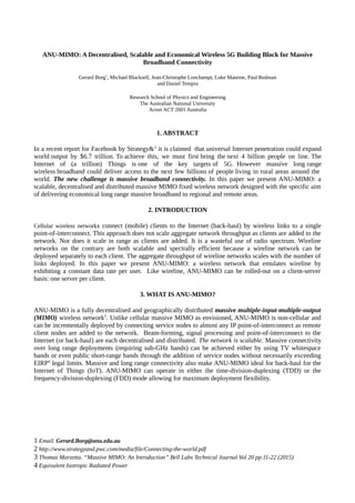
  • 2. Figure 1 shows an example deployment scenario of the ANU-MIMO network. A very large number of service nodes located in an Internet-connected area such as a city or a regional town centre use distributed beam-forming to wirelessly connect a large but lower number of remote clients on the same radio spectrum. The back-haul links from each service node to the Internet could be wireline links (such as copper or fibre) or local WiFi hot spots. If the service nodes form an isolated test network, then the back-haul could be provided by a network switch. If the remote clients are isolated from each other, then each receives a data rate consistent with the full bandwidth of the radio spectrum, provided that the back-haul connectivity of the service nodes is sufficient. The back-haul network needs to support not only the data rate demanded by a single remote client but also the beam sample rate of a single client. The network can be rolled-out starting with just a single service node-client pair. The range of the network grows as nodes are added due to the scaling of net RF power. The architecture of the network admits another exciting scenario. If more than one remote client are inter- connected by a sufficiently high speed shared network of their own (such as an Ethernet LAN), then their wireless links can be aggregated to form a single link to the service nodes of bandwidth equal to the sum of the bandwidths of the individual links. Similarly, if all remotes can be inter-connected by a sufficiently high speed shared network, then their bandwidths can be aggregated to form a massive wireless point-to-point link to the service nodes. Assuming MHz of wireless bandwidth and a thousand remotes, then the service node to remote client network would have a throughput of Gbps. Figure 1. A schematic picture of the ANU-MIMO network. Internet connected service nodes shown in ref are mounted on buildings in an Internet-connected township or city. Remote clients shown in blue are connected to the Internet over a scalable, decentralised and distributed massive MIMO wireless network.
  • 3. 4. ANU-MIMO OPERATIONAL CONCEPT The operation of ANU-MIMO is illustrated in the sequence of sketches A-C of Fig. 2. These sketches show service nodes in red, clients in blue and the existing Internet back-haul in green. Service nodes are connected to the Internet using dedicated links (green lines) such as for example wireline or WiFi. In case A, only client 2 is connected. As the client is within range of service node 5, it pairs with node 5 which is responsible for data coding. The blue line shows Internet data travelling to and from the Internet. In this case there is no beam-forming and no other service nodes participate. In case B, client 3 comes on line and pairs with base 7. Since clients 2 and 3 are mutual interferers, MIMO processing must be performed by at least service nodes 5 and 7. For this they share MIMO signalling or beam-forming samples over the Internet as shown by the red lines. The Internet data of clients 2 and 3 are shown in blue: client 2 pairing with node 5 and 3 with 7. Internet data will usually share the same back-haul link as the MIMO signalling data. In case C five clients come on line and pair with service nodes 2,3,5,6 and 7 respectively. Each of the 8 service nodes do MIMO processing and therefore share MIMO signalling samples over the Internet. A crucial feature of ANU-MIMO is that the MIMO beam-forming sample demand from each service node to the back-haul is equal to the beam sample demand of a single client, independently of the number of active service nodes deployed on the network. VIZ.Thebeamforming sampledemand →the datademand of asingleclient . Figure 2. ANU-MIMO operation
  • 4. 5. ANU-MIMO PHYSICS For a down-link massive MIMO channel with M service nodes, K clients and SINR signal-to- interference-plus-noise ratio, C the total capacity, for a conjugate precoder, is bounded by5 , C ≥ K log2(1+SINR) Consider first a regular cellular massive MIMO network as proposed for 5G. For a cellular massive MIMO network with fixed wireless access (in the long coherence time limit), the SINR is given by6 , SINR= M ρf K( ρf +1) where ρf is the average signal-to-noise ratio (SNR) for one service node and one client. This formula assumes that the total power of the array is kept constant as M →∞ which is a reasonable assumption for tower mounted service nodes in cellular networks in order to avoid inter-cell interference. It follows that SINR→0 as ρf →0 for constant M K , even as M →∞ Conclusion: For cellular massive MIMO, C →0 as ρf →0 . The range of the network is bounded. Now consider a massive MIMO network with geographically distributed service nodes. Due to the sparsity of the service node network, each station is entitled to emit the same EIRP (equivalent isotropic radiated power). It may be shown that in this case the SINR is given by, SINR= M 2 ρf K (M ρf +1) It follows that SINR→const . as ρf →0 , M K →const . and M ρf →const . as M →∞ . Conclusion: For ANU-MIMO, Capacity →const. and the range of the network increases as M →∞ . Notice that ANU-MIMO capacity is interference limited for K →M . For ANU-MIMO, the capacity per client per unit radio bandwidth is given by, C=log2 (1+G),where G= M K ⋅ M ρf M ρf +1 5 H. Yang and T. Marzetta, 'Performance of Conjugate and Zero-Forcing Beamforming in Large-Scale Antenna Systems,' IEEE Journal On Selected Areas in Communications. Volume 31 Issue 2 pp. 172-179 2013. 6 Ibid.
  • 5. 6. PERFORMANCE COMPARISON OF ANU-MIMO TO CELLULAR ANU-MIMO's massive connectivity could position it to provide back-haul for LTE networks and femto cells connecting the IoT in 5G. A single ANU-MIMO remote client using FDD with 20MHz per radio channel and QPSK can achieve 20Mbps on each of the forward and reverse link. This aggregate throughput rate for a network of K remote clients is K ×20 Mbps . A performance comparison to a conventional cellular LTE network is shown in Fig. 1. LTE has a single user capacity of 150Mbps. However as clients enter the cell and share the same radio spectrum, the throughput per client drops linearly with the number of clients. For ANU-MIMO, the throughput per client stays constant and the aggregate throughput of the network rises linearly as clients come on-line. Figure 3. Comparison of throughput for the ANU-MIMO network and LTE with 20MHz per FDD channel. The general points of difference between the ANU-MIMO network and cellular networks are: 1. ANU-MIMO is non-cellular. Its aggregate throughput and range scale as active service modes are deployed. 2. The ANU-MIMO network back-haul is distributed. Multiple points of connection to the Internet allow ANU-MIMO to connect clients to dedicated back-haul. This is more similar to wireline networking than wireless. The demand per service node on the back-haul is not affected by the number of service or client nodes added to the network.
  • 6. 7. ROLE OF ANU-MIMO IN 5G ANU-MIMO is targeted at massive connectivity for rural/remote broadband. It is interesting to compare this to the 5G drivers. Figure 4 shows the operational space of 5G in a three dimensional representation with aggregate throughput spatial density (kbps/km2 ), latency delay (ms) and links per km2 on the axes. The figure has been inspired by a similar diagram in a publication by Huawei Technologies7 . The green volume shows the entire 5G space and some typical applications in the yellow bubbles. The most demanding application is the case of multi-user UHD telepresence delivery to a densely populated area. The grey volume shows how the ANU-MIMO network fits into the 5G space. Calculations for our network were performed for 922MHz carrier frequency, per user bandwidth of 10Mbps and 1000-10000 service antennas. The vertical axis is essentially unconstrained because IoT devices use very little bandwidth. Assuming ANU-MIMO is applied to IoT, one could also connect many low bandwidth devices at the same remote terminal. But ANU-MIMO can also do broadband. The boundaries of performance of the ANU-MIMO network are at over 107 kbps/km2 for a short range network of 1km radius and less than 10ms latency. The densification is limited by wavelength and network spatial coverage. The latency figure applies to our existing demonstrator but is ultimately physically limited by the back-haul network. Importantly, the range of IoT systems such as LoRa8 is achieved by techniques such as chirp spread spectrum which permits long range, narrowband massive connectivity. ANU-MIMO however is designed for long range broadband massive connectivity. Figure 4. 5G operational space (green). ANU-MIMO network operational space (grey). 7 Huawei Technologies Co., Ltd.“5G A Technology Vision” 2013 (www.huawei.com/ilink/en/download/HW_314849) 8 http://www.slideshare.net/BrunoHAMAMLIAN1/lorawan101what-is-it
  • 7. 8. REGIONAL INTERNET BROADBAND SIMULATION Fig. 5 shows a MATLAB simulation of an ANU-MIMO deployment for regional town centre Bryan, College Station Texas, USA with 2048 service nodes and 1024 clients. The service nodes are located inside a 5.5km square within the town. We assume:  line-of-sight or Friis propagation on 62.55 MHz (8MHz channel bandwidth).  Flat terrain with ambient atmospheric noise figure 40dB above thermal (low VHF).  Single omni-directional dipole antennas on all stations.  QPSK signalling and conjugate match up and down-link coding.  LDPC (low density parity check) 1⁄2-rate code. Date rate per user 8Mbps. Figure 5. ANU-MIMO simulation for 1024 clients within 100kms of College Station Texas, USA. In the figure, service nodes (light green grid) are located within the town so that signalling can be performed over the existing wireline backhaul. The clients (red spots) are uniformly distributed over a range of 200 kms. Service nodes radiate isotropically ~ 133mW and clients in the range 14mW – 1.1W. The total RF power is about 699W, 273W from all service nodes and 426W from all clients. Error free operation appears feasible for an 8MHz operating bandwidth. Apart from the number of stations deployed, the only difference between this simulated network and the current prototype is the implementation in the simulation of a simple power control algorithm to circumvent the near-far effect.
  • 8. We can corroborate these results by using experimental data taken at 59MHz, 2MHz bandwidth on an experimental single link in the Australian Capital Territory, Australia. For distances up to 36kms in typical terrain (200m differential elevation) a client could receive a signal at ~20dB SNR from a single roof mounted aerial with a transmit power of 20W. The service antenna array in the figure covers several kilometers and looks to each client like a massive distributed M 2 K ×0.133≈545W aerial. Using Friis transmission to scale up the experimental single link to correspond to the simulation would require a power (100kms/36kms)2 ×(8 MHz/2MHz)×(20W )=617W in good agreement with the expected value of 545W. 9. CONCLUSION In this paper we have described how ANU-MIMO works, how it fits into 5G, how it compares to LTE and what a typical deployment scenario looks like. ANU-MIMO is also a very economical network to deploy because service nodes can be connected at existing back-haul to the Internet or alternatively, via a multi-port network switch. ANU-MIMO can also provide back-haul for the IoT in 5G. ANU-MIMO is therefore ideal for community groups and local governments who need to connect significant remote populations of disadvantaged users that would be currently counted amongst the four or so billion unconnected users on the planet. Connecting these populations to the Internet would add significantly to the world economy. Therefore ANU-MIMO provides a key technology to bring about the democratisation of the Internet. ACKNOWLEDGEMENTS The authors acknowledge the support of the Research School of Physics and Engineering in the College of Physical and Mathematical Sciences, Australian National University.