IRJET - IC Engine Waste Heat Recovery Systems
•
0 gefällt mir•35 views

https://www.irjet.net/archives/V7/i4/IRJET-V7I417.pdf

Empfohlen
Empfohlen
Weitere ähnliche Inhalte
Was ist angesagt?
Was ist angesagt? (20)
Ähnlich wie IRJET - IC Engine Waste Heat Recovery Systems
Ähnlich wie IRJET - IC Engine Waste Heat Recovery Systems (20)
Mehr von IRJET Journal
Mehr von IRJET Journal (20)
Kürzlich hochgeladen
Kürzlich hochgeladen (20)
IRJET - IC Engine Waste Heat Recovery Systems
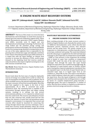
- 1. International Research Journal of Engineering and Technology (IRJET) e-ISSN: 2395-0056 Volume: 07 Issue: 04 | Apr 2020 www.irjet.net p-ISSN: 2395-0072 © 2020, IRJET | Impact Factor value: 7.34 | ISO 9001:2008 Certified Journal | Page 78 IC ENGINE WASTE HEAT RECOVERY SYSTEMS Jabir PP1, Jishnuprakash2, Sajid K3, Sakkeer Hussain Chalil4, Salmanul Faris PK5, Sanjay KN6, Sarathkumar7 1Lecturer, Department of Mechanical Engineering, Orphanage Polytechnic College, Edavanna, Kerala, India. 2,3,4,5,6,7Diploma students, Department of Mechanical Engineering, Orphanage Polytechnic College, Edavanna, Kerala, India ---------------------------------------------------------------------***---------------------------------------------------------------------- ABSTRACT - The focus of this study is to review thelatest developments and technologies on waste heat recovery of exhaust gas from internal combustion engines (ICE). These include thermoelectric generators (TEG), organic Rankine cycle (ORC), six-stroke cycle IC engine and new developments onturbochargertechnology.Furthermore, the study looked into the potential energy savings and performances of those technologies. The current worldwide trend of increasing energy demand in transportation sector are one of the many segments that is responsible for the growing share of fossil fuel usage and indirectly contribute to the release of harmful greenhouse gas (GHG) emissions.It is hoped that with the latest findings on exhaust heat recovery to increase the efficiency of ICEs, world energy demand on the depleting fossil fuel reserves would be reduced and hence the impact of global warming due to the GHG emission would fade away Key Words: Waste Heat Recovery, Organic Rankine Cycle, Thermoelectric Generator. INTRODUCTION Recent trend about the best ways of using the deployable sources of energy in to useful work in order to reduce the rate of consumption of fossil fuel as well as pollution. Out of all the available sources,theinternal combustion enginesare the major consumer of fossil fuel aroundtheglobe.Outof the total heat supplied to the engine in the form of fuel, approximately, 30 to 40% is converted into useful mechanical work. The remaining heat is expelled to the environment through exhaust gases and engine cooling systems, resulting in to entropy rise and serious environmental pollution, so it is required to utilized waste heat into useful work. The recovery and utilization of waste heat not only conserves fuel, usually fossil fuel but also reduces the amount of waste heat and greenhouse gases damped to environment. It is imperative that serious and concrete effort should be launched for conserving this energy through exhaust heat recovery techniques. Such a waste heat recovery would ultimately reduce the overall energy requirement and also the impact on global warming WASTE HEAT RECOVERY IN AUTOMOBILES i. ORGANIC RANKINE CYCLE METHOD Basic working principle of the waste recovery system is based on Organic Rankine cycle. Basically the system works on 4different thermodynamic cycles which describe heat absorption process, expansion process, heat rejection process and the pump work. The system consists of an evaporator or a heat generator, a turbine basically scroll or screw type, condenser and a pump. The waste heat obtained from the exhaust gas is supplied into the shell and tube heat exchanger ie, the evaporator ata temperaturearound2000C – 2500C at 5 bar pressure. In the evaporator the working fluid is heated to super heat condition at temperature around 100C inside the tube of the shell and tube heat exchanger. Now through the vapor line super heated refrigerant vapor flows into a turbine having singlestage. By the expansion of super-heated vapor in turbine, turbine starts rotating thus required outputpowerisproduced.Now the expanded vapor is in the form of super-heated state or saturated vapor state or in liquid vapor form at exit condition i.e., about at 1 bar. This vapor is now fedintoa water cooled condenser, where the vapor is condensed into the liquid form. Now this liquid refrigerant is fed through liquid line and is pumped to the working pressurei.e.at5bar by means of a positive displacement pump basically a diaphragm pump. The cycle is repeated for 'n' number of cycles. Now the micro turbine is coupled to an alternator to produce electrical energy and stored in a battery.. Rankine Cycle Diagram
- 2. International Research Journal of Engineering and Technology (IRJET) e-ISSN: 2395-0056 Volume: 07 Issue: 04 | Apr 2020 www.irjet.net p-ISSN: 2395-0072 © 2020, IRJET | Impact Factor value: 7.34 | ISO 9001:2008 Certified Journal | Page 79 Scope of the Work This work focuses on the Rankine cycle as the most promising existing technology for engine waste heat recovery in terms of recuperation efficiency. While it is a comparatively mature technology and is widely used in power generation, its use in vehicles presents new challenges in system design. Thesestemfrom environmental and packaging issues, as well as difficulties relating to the quality and quantity of the available heat and its transient availability. It is not yet clear which working fluid and expansion device are optimal for use in a Rankine cycle- based system for vehicular applications. However, previous studies have indicated that these components areamong the most important factors for the system’s performance. The Rankine cycle is a promising technique to recover waste heat. This additional amount of heat recovered implies impacts on aerodynamic of the truck and/or on the existing cooling system. A simple Rankine cycle basedonexhaustgas has been preferred as it is today a heat source that exists on all existing engines on the market (EGR ornonEGR engines). By recovering on engine exhaust gases, the Rankine cycle will affect the engine fuel consumption because of higher pressure losses on the exhaust line. The challenge for waste heat ADVANTAGES High turbine /thermodynamic cycle efficiency Turbine low mechanical stress No need de mineralize water No risk of blade erosion Complete automatic Simple maintenance procedure DISADVANTAGES very low pressure, high specific volume, big installations needed (turbine, condenser, etc) high pressure drop to become a high enthalpydrop: expensive multi-stage turbines needed expansion has to start in the superheated area to avoid too much moisture content after expansion efficiency loss and limited suitability to waste heat recovery APPLICATIONS The Organic Rankine Cycle (ORC) is a well matured waste heat recovery technology that can be applied in vehicle power trains, mainly due to the low additional exhaust backpressure on the engine and the potential opportunity to utilize various engine waste heat sources. ii. THERMOELECTRIC GENERATOR METHOD Thermoelectric generators (TEG) are solid-state semiconductor devices that convert a temperature difference and heat flow into a useful DC power source. Thermoelectric generator semiconductor devices utilizethe Seebeck effect to generate voltage. This generated voltage drives electrical currentandproducesuseful powerata load. Thermoelectric Generator Module A thermoelectric generator is not the same as a thermoelectric cooler. (also known as TEC, Peltier module, cooling chips, solid-state cooling) A thermoelectric cooler works inreverseofa thermoelectric generator. When a voltage is applied to thermoelectric cooler, an electrical current is produced. This current induces the Peltier effect. With this effect, heat is moved from the cold side to the hot side. A thermoelectric cooler is also a solid-state semiconductordevice.Thecomponents are the same as a thermoelectric generator but the design of the components in most cases differ. While thermoelectric generators areusedtoproducepower, thermoelectric coolers (Peltier coolers) are used for removing or adding heat. Thermoelectric cooling has many applications in cooling, heating, refrigeration, temperature control and thermal management. ADVANTAGES Reliability Quiet No Greenhouse Gases Wide Range of Fuel Sources Scalability DISADVANTAGES Thermoelectric generators are less efficient than some of the other energy conversion technologies. Thermoelectric generators can have a higher initial cost per watt of electrical power output than some energy conversion technologies for some applications.
- 3. International Research Journal of Engineering and Technology (IRJET) e-ISSN: 2395-0056 Volume: 07 Issue: 04 | Apr 2020 www.irjet.net p-ISSN: 2395-0072 © 2020, IRJET | Impact Factor value: 7.34 | ISO 9001:2008 Certified Journal | Page 80 There is a fair amount of thermoelectric generator module manufacturing knowledge CONCLUSIONS The internal combustion (IC) engine is probably the most important heat engine nowadays but still has a major drawback: most current enginedesigns rejectmorethanhalf of the supplied fuel energy in the form of heat losses. There is a pressing need to improve the efficiency of IC engines because of the danger of climate change and the earth’s diminishing fossil fuel reserves,makingtheuseofwasteheat recovery systems for IC engines increasingly attractive. Systems based on the Rankine cycle are considered to be among the most promising technologies for this purpose because of their heat recovery efficiency. It has been observed that there is a large amount heat is waste from the engine. Approximately heat lost by exhaust as is same to useful work produced by engine. It is identified that there is large potential of energy saving through the use of waste heat recovery technologies. The recovery and utilization of waste heat not only conserves fuel but also reduces the greenhouse gases and waste heat by increasing efficiency of engine. This study shows the Benefits of waste heat recovery, Heat carried away by the exhaust gas, various possible methods for heat recovery. This also showsthatthe new concept of Heat wheel may be used for exhaust gas heat recovery for intake air preheating of Diesel engine. ACKNOWLEDGEMENT We extend our deep sense of gratitude to our project guide Mr. Jabir. PP, Lecturer, Department of Mechanical Engineering for providing us with valuable guidance and whole hearted encouragement throughout the project. We express our sincere thanks to Mr. Mansoor Ali PP Principal, Orphanage Polytechnic College Edavanna for the support and constant encouragement. We express our sincere gratitude to Mr. Binu. KK, Head of Department, Department of Mechanical Engineering for the support and constant encouragement. We thank all the teaching and non-teaching staffs, our classmates and friends for sharing their knowledge and valuable suggestions. REFERENCES 1. Pradip G. Karale1 Dr. J.A Hole2, Experimental investigations of performance and emissions of Karanja oil and its blends in a single cylinder diesel engine. Applied Energy 86, 106–112, 2009. 2. J. S. Jadhao, D. G. Thombare, Impact of compression ratio and injection parameters on the performance and emissions of a DI diesel engine fueled with biodiesel-blended diesel fuel‖ , Applied Thermal Engineering 31, 3182- 3188, 2011. 3. P. P. Sonune, H. S. Farkade, Straight vegetable oils usage in a compression ignition engine a review , Renewable and Sustainable Energy Reviews 14, 3005–3013, 2010. 4. R. SelvanDr. K. Maniysundar Performance and emissions characteristics of Jatropha oil (preheated and blends) in a direct injection compression ignition engine. Applied Thermal Engineering 27, 2314–2323, and 2007. 5. Charles Sprouse III, Christopher Depcik, Performance and emission evaluation ofa CIengine fueled with preheated raw rapeseed oil (RRO) diesel blends , Applied Energy 87, 786–790, 2010. BIOGRAPHIES Jabir PP Lecturer Dept.of mechanical engineering O.P.T.C edavanna Malappuram, kerala Salmanul Faris PK Koraliyattil Trippanachi PO Malappuram, kerala Jishnu Prakash K Nandanam Thenhipalm PO Malappuram, kerala Sajid K Kuppanath Vadapuram PO Malappuram, kerala Sanjay KN Kunnummal Pathirippadam PO Malappuram, kerala Sarath Kumar A Arimbra Porur PO Malappuram, kerala Sakeer hussain chalil Chalil O.K muri PO Malappuram, kerala