SlideShare ist ein Scribd-Unternehmen logo
1 von 7
Downloaden Sie, um offline zu lesen
International Research Journal of Engineering and Technology (IRJET) e-ISSN: 2395-0056
Volume: 09 Issue: 11 | Nov 2022 www.irjet.net p-ISSN: 2395-0072
© 2022, IRJET | Impact Factor value: 7.529 | ISO 9001:2008 Certified Journal | Page 656
Introduction of 132/11 kV Digitally Optimized Substation for Protection,
Control and SCADA System in DEWA Transmission Network
Owen Raymond Glynn, Jayasingh Balakrishnan, Amod Madhukar Khirwadkar, Murali Kandakatla,
Muthu Samy Veerabahu
Transmission Protection Department, Dubai Electricity & Water Authority.
--------------------------------------------------------------------------***--------------------------------------------------------------------------
Abstract- Dubai’s transmission power system plays a vital
role in delivering optimum reliability and uninterrupted
power. We therefore need to maintain the highest levels of
technology, operational and cyber security best practices for
all digital systems.
This paper aims to provide the conceptual overview and
benefits of a digitally optimized substation design. The new
design includes control, protection and cyber security
systems supplied from different vendors from across the
globe which are engineered, configured and extensively
laboratory tested to ensure perfect functionality of these
highly complex and challenging digital technologies.
Identifying the latest technologies available and
implementing these in innovative new ways has produced
new designs that enhance functionality and reliability whilst
reducing large quantities of discreet components and
circuitry.
At station level, virtual technologies are introduced and are
embedded in two servers each of which includes all SCMS,
cyber security, engineering workstation and data storage
with seamless redundancy similar to cloud computing server
centers. Servers are configured in a cluster configuration with
the remote OT data center as witness server. All applications
run in a dedicated virtual machine and virtual security scans
and records all traffic with artificial intelligence monitoring
performed at the cyber security operations center (CSOC).
At 132kV bay level, duplicate and integrated control and
protection is introduced through two multifunction
intelligent electronic devices (IED’s) per bay, each from a
different manufacturer. All inter-bay connections are
digitized through
IEC61850 process bus, which are engineered to be
interoperable and interchangeable between different
manufacturers without the need for reconfiguration. The
latest IEC61850-9-2 compliant IED’s provide enhanced digital
fault recording capability which automatically transmits fault
records through the IEC61850 network in the common
Comtrade file format. Fault records are automatically
available at the station HMI and at the central data center.
Remote access to all IED’s is provided through a secure
virtual desktop application. Role based access, centralized
user and password management is managed by a specialist
OT security team.
The unique new designs were developed in house by DEWA
specialists in conjunction with specialists from the original
equipment manufacturers and software developers. The
digitally optimized substation (DOSS) is a completely new
design focused on digitization and optimization of all control,
protection, data acquisition communications and cyber
security systems.
The digitization of thousands of components and reduction of
over 100km of copper wiring delivers significant reduction in
carbon footprint, reduction in building size, energy saving,
cost reduction while improving the functionality and
reliability of the transmission power system. This innovative
initiative will ensure that DEWA will have arguably the most
advanced substations both regionally and globally by
introducing the latest digital technologies, optimized designs
in line with the industry leading best practices.
I.INTRODUCTION
Dubai Electricity & Water Authority (DEWA) was
established in 1992 by His Excellency Sheikh Maktoum bin
Rashid Al Maktoum with the objective to provide reliable
power to residents of the Emirate of Dubai. Since its
inception, DEWA has continuously invested in maintaining
and upgrading the power delivery infrastructure to meet
the increasing demands of the growing Emirate of Dubai.
Dubai Electricity & Water Authority (DEWA) Power System
includes Generation, Transmission and Distribution
networks. The transmission network operates at 400kV and
132kV voltage levels with over 350 transmission
substations consisting of 400/132kV, 132/33kV and
132/11kV sites.
International Research Journal of Engineering and Technology (IRJET) e-ISSN: 2395-0056
Volume: 09 Issue: 11 | Nov 2022 www.irjet.net p-ISSN: 2395-0072
© 2022, IRJET | Impact Factor value: 7.529 | ISO 9001:2008 Certified Journal | Page 657
The new substation designs take the latest equipment and
technologies, applies them to substations in new and
innovative ways that benefit the environment, DEWA and the
community.
II.DIGITAL SUBSTATIONS: FACTS VS MYTHS
A full digital substation by definition includes low power
instrument transformers (LPIT’s) also known as non-
conventional instrument transformers (NCIT’s). These NCIT’s
are connected to merging units, which perform analogue to
digital conversion, applies a time stamp in order for the
sampled values to be transmitted over an ethernet network.
However, looking carefully at the concept of a digital
substation, it is evident that since the NCIT’s are analogue
devices that produce an analogue sinusoidal output, these
systems are no more digital than conventional instrument
transformers. The fact remains that substations transport
power which is the product of voltage and current which are
analog quantities both at primary and at secondary levels. We
can therefore conclude that the term full digital substation is
somewhat misleading.
A. Comparison of NCIT Vs. Conventional CT
In full digital substations non-conventional instrument
transformers for measuring current are either a rogowski coil
or optic sensor both of which are analog systems as shown in
Figure1. These NCIT’s transfer analog quantities in
proportion to the measured primary quantities to merging
units (MU) which perform analog to digital (A to D)
conversion much the same as conventional IED’s which
already have built in A to D converters based on 1 amp input
rating. The significant different appears at the output of the
merging unit which transmits the measured data through
ethernet. This is where the system becomes complex since
ethernet does not have a definite or a fixed data transmission
time. This is unacceptable for protection systems, which will
become unstable due to measurement misalignment.
The merging units therefore need to time tag each sample
before transmitting. Since the IED’s are sampling at about
8kHz this amounts to a very large amount of data being
transmitted for the 3phases plus neutral for currents and
voltages from each merging unit. This data is transmitted
through the process bus which in turn has the effect of
slowing the ethernet speed. The additional cost, complexity,
additional components with the obvious adverse impact on
reliability would logically be implemented if there were some
significant benefits. The claimed benefit is that NCIT’s
produce a more linear and accurate measurement, which
may be true if there was an identified reason why the
conventional system was not adequate. Since protection IED’s
have very advanced filtering and algorithms capable of
maintaining optimum performance even with significant
nonlinearity or saturation during faults – this advantage is
negligible in almost all applications.
For most applications it therefore becomes evident that the
use of merging units is unwarranted and are an additional
equipment required to be used that reduces overall reliability
and availability of the power system.
AnalogmA
Analog1A
Rogowski Coil NCIT
Conventional CT
Merging Unit Ethernet
Switch
Both systemsuseanalog
measurement through an A to D
converter.
A to D
converter
isbuilt in
Process
Bus
Fig1: Comparison of conventional CT vs Rogowski coil
NCIT
Non-conventional instrument transformers for all substation
equipment such as bushing CT, Reactor internal CT and
transformer neutral CT are not available especially for
applications which are immersed in oil. This makes a full
digital substation using all NCITs not possible.
In DEWA a typical 132/11KV substation has 71 x 11kV bays
which would result in a large number of merging units and a
large amount of data on the process bus. The additional cost,
complexity and the fact that OEM’s are unable to provide a
consistent solution makes this option impractical considering
that there is no benefit to the power system.
B. Reliability of NCIT Vs. Conventional CT
A quick comparison of NCIT with conventional CTs is as
shown in table below. A NCITI requires a matching merging
unit which needs to be considered as part of the measuring
system when compared to a conventional CT which does not
require additional components in order to connect to IED’s. It
is evident that NCIT does have several disadvantages over
conventional CTs in terms of mean time between failure
(MTBF), performance, life expectancy etc. This is a separate
International Research Journal of Engineering and Technology (IRJET) e-ISSN: 2395-0056
Volume: 09 Issue: 11 | Nov 2022 www.irjet.net p-ISSN: 2395-0072
© 2022, IRJET | Impact Factor value: 7.529 | ISO 9001:2008 Certified Journal | Page 658
subject and the details are not covered in this paper;
however, it is evident that use of NCIT/sensors with merging
units does not offer any great advantages towards substation
digitization as shown in Table-1.
Table-1 Conventional CT Vs NCIT
Description
Conventional
CT
Sensor +
Merging Unit
(NCIT)
Life expectancy > 40 years 20 years
Mean time
between failures
(MTBF)
1,506,939 500
Replacement
strategy
Not required
May require new
GIS
Consequence of
failure
1 x protection
out
Feeder + Busbar
prot. + Control
out
Probability of
interruption
Low High
Performance Medium High
Advantage Reliability
Claim of full
digital
III. DIGITALLY OPTIMIZED SUBSTATION DESIGN
DEWA took the initiative to review the digital substation
concept and developed an innovative digitally optimized
substation (DOSS) design. The new design retains the proven
reliable conventional instrument transformers and utilizes
the most practical and beneficial digital substation concepts
of process & station bus. The DOSS design utilizes the latest
smart technology available in intelligent electronic devices
(IED’s) which allows customizing and optimizing the
configuration of the control and protection systems in
substations while reducing the number of auxiliary relays
and components. This approach ultimately achieves the best-
engineered solution whilst achieving higher reliability, cost
reduction and lower carbon footprint.
The key features of the DOSS design are:
ď‚· Consistent substation design irrespective of the
contractors/ OEMs.
ď‚· More efficient design approval process for new
substation projects.
ď‚· Reduction in time required for project design approvals,
testing & commissioning.
ď‚· Additional benefits such as reduction of maintenance
cost, ease of operation and simplification of the
substation design.
ď‚· Using conventional instrument transformers ensures
that protection and control systems can be refurbished
in future without the risk of needing to replace
instrument transformers or possibly switchgear.
The digitally optimized substation simplified architecture is
shown in Figure-2.
Switches
SubstationHMI
Station B
us
Copper Hardwiring
IE
C61850
GOOS
E
IE
C61850
GOOS
E
Bay-1 BCPU1 Bay-n BCPU1 Bay-1 BCPU2 Bay-n BCPU2
GISSwitchgear Status& Alarms Conventional CT / VT Equipment Sensor Data
A. The Basis of Design Optimization
Optimization of control and protection system considered
the following main aspects:
ď‚· Protection & Control functions are integrated in single
Intelligent Electronic Device (IED)
ď‚· Hard-wired interlocks replaced with digital signals
(IEC61850 GOOSE signals over process bus).
ď‚· Electromechanical relays replaced with digital
functions.
ď‚· Reduction or elimination of CTs.
ď‚· Integrated busbar and feeder backup protections for
11kV network.
ď‚· Integrated Tap Change Controller (AVR).
ď‚· Removal of 24 x metering units on 11kV.
ď‚· Elimination of external DFR devices by utilizing the
inbuilt fault recorder capabilities in IEDs.
Figure-2: Simplified DOSS Architecture
International Research Journal of Engineering and Technology (IRJET) e-ISSN: 2395-0056
Volume: 09 Issue: 11 | Nov 2022 www.irjet.net p-ISSN: 2395-0072
© 2022, IRJET | Impact Factor value: 7.529 | ISO 9001:2008 Certified Journal | Page 659
ď‚· Each bay shall have two independent and redundant
protection and control systems.
ď‚· Two independent auxiliary DC systems for BCPU-1 &
BCPU-2, to avoid common mode failure.
ď‚· Protection schemes engineered to produce efficient
designs with minimum number of auxiliary
components.
ď‚· Standardization of SCADA alarm lists with reduced
number of alarms to the master control station.
B. Details of Design Optimization for a Typical 132kV
Feeder Bay
For a typical 132kV feeder bay the existing conventional SS
design and new digitally optimized SS design are as shown
in Figure-3.
Integrated
Protection,BCU,
SynchCheck,
VSSandDFRin
bothBCPUs
Digital Busbar
Protectiondoes
not requirea
separateCT for
theCheckZone.
Figure-3: Feeder bay design in conventional & DOSS
design
The protection and control designs for a typical feeder bay
in conventional and new DOSS designs are compared in
Table-2.
Table-2: Comparison of Feeder bay design in
conventional & DOSS design
Application
Existing
Conventional SS
Design
Digitally Optimized
SS Design
Bay
Protection
Main-1 Protection
(M1FP)
Bay Control &
Protection Unit-1
(BCPU1)
Main-2 Protection
(M2FP)
Bay Control &
Protection Unit-2
(BCPU2)
Bay Control
Bay Control Unit
(BCU)
Not Applicable
(Integrated to
BCPU1, 2 and
Respective CT core
eliminated)
Fault
recorder
DFR
Busbar
protection
High Impedance
Main-1 Protection
(M1BZP)
Low Impedance
Main-1 Protection
(M1BZP)
Low Impedance
Main-2 Protection
(M2BZP)
Low Impedance
Main-2 Protection
(M2BZP)
DOSS designs include integrated control & protection panels
(CPP) instead of separate protection and control LCC panels.
A comparison of existing and new panels are as shown in
Figure-4.
Existing132kVFeeder
ProtectionPanel Existing132kVFeeder LCCPanel
Bay
Controller
BCPU2
BCPU1
All Protection, Bay Control, Voltage
Selection Scheme, DFR& Interlocks
are integrated into new BCPU’s
with complete redundancy.
New132kVControl& Protection
Panel (CPP)
Main1
Prot.Relay
Main2
Prot.Relay
Figure-4: Feeder bay panels between conventional and
DOSS design
International Research Journal of Engineering and Technology (IRJET) e-ISSN: 2395-0056
Volume: 09 Issue: 11 | Nov 2022 www.irjet.net p-ISSN: 2395-0072
© 2022, IRJET | Impact Factor value: 7.529 | ISO 9001:2008 Certified Journal | Page 660
Accordingly, similar optimizations are done for all 132kV
and 11kV bays in the new DOSS design. As per the new
BCPU and BMP functionality, the protection & control IED’s
are prequalified and approved after successful laboratory
testing.
The approved BCPU, BMP IEDs for some of the applications
are as shown in below Table-3.
Table-3: Prequalified BCPU, BMP IEDs for DOSS SS
Voltage
Level
Typical Bay Application IED Make IED Type
132kV Feeder
BCPU1 /
BCPU2
Siemens 7SL87
SEL 411L
Hitachi RED670
132kV Bus Coupler
BCPU1 /
BCPU2
Siemens 7SJ85
SEL 451
Hitachi REC670
132kV
IDT
Transformer
BCPU1 /
BCPU2
Siemens 7UT85
SEL 487E
Hitachi RET670
11kV
Feeder,
Incomer &
Capacitor
Feeder
BMP
Siemens 7SJ85
SEL 451
Hitachi REC670
C. SCMS Architecture in new DOSS Design
In the new DOSS design, the SCMS is completely redesigned
and introduces virtual technologies. The number of SCMS
components are greatly reduced whilst increasing reliability
and redundancy. The SCMS architecture utilized in new
DOSS design is as shown in Figure-5.
Station Switch-A (Level-2) Station Switch-B (Level-2)
LAN-A Field Switch
Substation HMI
NETWORK
C02
-BCPU1
C09
-BCPU1
C04
-BCPU1
C05
-BCPU1
C06
-BCPU1
C07
-BCPU1
C08
-BCPU1
C03
-BCPU1
M1BZP-R
M1BZP-Y
M1BZP-B
FDR
RXR-1
M1RP
FDR
RXR-2
M1RP
1
2
3
4
5
6
7
8
9
10
11
12
13
14
15
16
LAN-B Field Switch
1 2 3 4 5 6 7 8 9 10 11 12 13 14 15
OTS Panel-1
M2BZP-R
M2BZP-Y
M2BZP-B
132kV Digitally Optimized Substation – SCMS Topology
C02
-BCPU2
C03
-BCPU2
C04
-BCPU2
C05
-BCPU2
C06
-BCPU2
C07
-BCPU2
C08
-BCPU2
C09
-BCPU2
FDR
RXR-1
M2RP
FDR
RXR-2
M2RP
Metering System
(EMVS)
Common
BCU-1
OTS Panel-2
Thin
Client
Remote Access, Retrieval of Digital
Fault Records and DataManagement
System for Substation IED s
(Centralized Cloud Storage &
Engineering Workstation )
IT/ OT
PERIMETER
DEWA - IT Network
Dashboard /
Mobile Viewers
IED Configuration /
setting Users
DFR Users
(TPD & RTO)
OTS
DC-1
OTS
DC-2
EMVS-
1
EMVS-
2
TCC-1 DCC-1 DCC-2
TCC-2
Notes:
1. This concept topology does not
constitute a detailed design.
2. Substation Server includes
Security Systems, SCMS, EWS and
local storage.
GPS
CLOCK
SCMS Panel-1 SCMS Panel-2
Substation Server &
Gateway 1
(Virtual Security) (Virtual Security)
17
18
19
20
21
22
23
24
16 17 18 19 20 21 22 24
23
15
Substation Server &
Gateway 2
DC 1 Charger
Controller
DC3 Charger
Controller
DC 2 Charger
Controller
(Future)
C01
-BCPU1
(Future)
C01
-BCPU2
Common
BCU-2
11kV Bus 1 Loop
11kV BB
CU1
11kV BB
CU2
11kV BB
CU3
F01-BMP F02-BMP F22-BMP F23-BMP
11kV Bus 3 Loop
F48-BMP F49-BMP F70-BMP F71-BMP
Busbar Protection Central Units
11kV Bus 2 Loop
F24-BMP F25-BMP F46-BMP F47-BMP
11kV
Switchgear
Figure-5: SCMS architecture in DOSS design
D. Standardization of DOSS Design
Standardization in DOSS design achieved by preparing
standard design documents by DEWA and including them as
part of tender documents for contractor’s strict compliance.
The following are the standard design documents:
ď‚· Control and Protection specification.
ď‚· SCMS technical specification.
ď‚· DC technical specification.
ď‚· Metering technical specification.
ď‚· Conceptual protection single line diagrams, trip logics
and control & interlock logics for all the typical bays.
ď‚· Control and protection panel schematic and general
arrangements drawings.
ď‚· Substation DC system single line diagrams.
ď‚· Substation DC chargers schematic and general
arrangement drawings.
ď‚· Test terminal block standard terminal arrangements.
ď‚· Master station SCMS signal list with standard IEC61850
signal address.
ď‚· Standard CT & VT parameters for all bays and all
applications.
ď‚· BCPU/ BMP IEDs specific wiring templates for each
make and application.
In addition to above mentioned standard design documents,
pre-qualified manufacturers were also provided to the
contractors to select the approved vendors.
International Research Journal of Engineering and Technology (IRJET) e-ISSN: 2395-0056
Volume: 09 Issue: 11 | Nov 2022 www.irjet.net p-ISSN: 2395-0072
© 2022, IRJET | Impact Factor value: 7.529 | ISO 9001:2008 Certified Journal | Page 661
ď‚· Approved IEDs list.
ď‚· Approved protection and control component list.
ď‚· Approved energy meters list.
ď‚· Approved CT and VT manufacturers list.
ď‚· Approved panel manufacturers list.
ď‚· Approved DC system manufacturers list.
E. Digitally Optimized SS Design – Benefits
The new innovative digitally optimized substation design
provides significant benefits to DEWA as a utility. The new
design for 132/11kV substations includes the following
advantages:
ď‚· Protection & control functions are integrated into a
single IED (BCPU1/2): Reduction of 15 IEDs,
redundancy in control functions and 18 x control and
protection panels removed.
ď‚· Hard wired interlocks are replaced with peer-peer
GOOSE digital signals: Over 100km of copper cabling
eliminated.
ď‚· All electromechanical relays replaced with digital
systems: Over 8000 devices removed.
ď‚· Reduction in the number of current transformers: Total
258 units removed.
ď‚· Integrated busbar and feeder backup protection for
11kV network.
ď‚· Integrated tap change controller (AVR) into BMP IEDs:
Panel with 3 x controllers removed (digitized).
ď‚· Removal of 24 x metering units on 11kV.
 Integrated digital fault recorders (DFR’s): 3 x DFR
panels removed.
ď‚· Optimized SCMS system: 4 x SCMS panels, 5 x
computers, 2 x monitors, 20 x network switches, 196
fiber optic cables, 4 x fiber optic patch panels, 1 x GPS
clock removed.
ď‚· Virtual security, role based remote engineering access
through virtual machine is achieved.
The summary of removed equipment as part of the
132/11kV design optimized SS are as shown in Table-4.
Table-4: Summary of removed equipment in DOSS SS
S.No. Equipment
Description of
Change
Quantity of
Removed
equipment
1 132kV GIS
Reduce 13 x Sets = 39
CT's
39
2
132kV
Feeders
Remove 3 x 132kV
Protection Panels
3
3
132kV
IDT's
Remove 3 x 132kV
Protection Panels
3
4
132kV Bus
Coupler
Remove 1 x 132kV
Protection Panel
1
5 132kV LCC
Reduce 6,707 x
components (Aux
relays, timers,
terminals, mcb's,
switches etc.)
6707
6
11kV Feeder
with
Metering
Meters removed and
CT's for metering are
retained.
255
7
11kV
Feeder
without
Metering
Optimized with
reduced CT's and
components
672
8
11kV Cap
Bank
Reduced Capacitor
Bank Protection relay
and integrated into
BMP.
102
9
11kV
Incomer
Check Zone relay
removed, AVR
function integrated
into BMP.
81
10
11kV Bus
Sections
Reduced CT's and
several components
digitized
59
11
11kV
Busbar
Remove High
Impedance scheme
and implement Low
Impedance BBP with
integrated 11kV
Feeder Backup
protection. Reduce 73
x sets of CT's
3
12 LVAC
Remove 34
components including
High Impedance REF
& CT's
34
13 SCMS
SCMS panels &
components
232
14 AVR
Remove 1 x AVR
panels and
equipment’s
4
15
Digital Fault
Recorder
(DFR)
Remove 3 x DFR
panels and
equipment’s
3
Total 8198
International Research Journal of Engineering and Technology (IRJET) e-ISSN: 2395-0056
Volume: 09 Issue: 11 | Nov 2022 www.irjet.net p-ISSN: 2395-0072
© 2022, IRJET | Impact Factor value: 7.529 | ISO 9001:2008 Certified Journal | Page 662
Additionally, the new design will support DEWA’s vision
and environmental goals.
ď‚· The reduction in carbon emissions approximately 37
tons per year for 132/11kV substation due to annual
energy saving of 53MWH.
ď‚· Reduction in substation building size by 133m2.
ď‚· Savings of 7 million AED per substation due to reduced
equipment.
ď‚· The new design utilizes, control and protection panels
(CPP) developed in the UAE along with local
manufacturers.
IV. CONCLUSION
The DOSS design selects the best technologies available,
combines it with best design practices to achieve the
industry leading optimized substation design.
The innovative DOSS design concept can be implemented in
other organizations globally, which have the same business
portfolio (electricity supply), and this will positively
influence our responsibility to support the sustainable
development goals and protect the environment.
V. REFERENCES
[1] John bettler, Jesse Silva, Dan Morman, “Case Studies of
IEC61850 Process Bus Systems Using GOOSE and Sample
Values: Recent Installations and Research”, proceedings of
the 74th Annual Georgia Tech Protective Relaying
Conference, April-2021.
[2] Stefan Meier, Thomas Werner, “Performance
considerations in digital substation applications” white
paper presented at PAC World UK 2015.
[3] Greg Rzepka, Scott Wenke, Sarah Walling, “Choose
Simplicity for a Better Digital Substation Design”, 70th
Annual Conference for Protective Relay Engineers, Texas,
April-2017.
[4] Qinccui Fu, Jianyun Chen, “Design of Experiment
Platform for Digital Substation Based on IEC61850”, 5th
International Conference on Computer Science and Network
Technology (ICCSNT)-2016
[5] Topolsky D.V., Topolskaya I.G., Topolsky N.D,
“Development of an Intelligent Measuring System for Digital
Substations”, International Multi conference on Industrial
Engineering and Modern Technologies (FarEastCon)-2018.
[6] E.V. Solomin, D.V. Topolskiy, N.D. Topolskiy, “Integration
of Adaptive Digital Combined Current and Voltage
Transformer into Digital Substation Ethernet Grid”,
International Siberian Conference on Control and
Communications (SIBCON)-2015.

Weitere ähnliche Inhalte

Ă„hnlich wie Introduction of 132/11 kV Digitally Optimized Substation for Protection, Control and SCADA System in DEWA Transmission Network

Nokia_Sub-station_Automation_White_Paper_EN
Nokia_Sub-station_Automation_White_Paper_ENNokia_Sub-station_Automation_White_Paper_EN
Nokia_Sub-station_Automation_White_Paper_EN
Juan Boggiano
 
Advantech Intelligent Communication Gateways are ARM-based robust platforms w...
Advantech Intelligent Communication Gateways are ARM-based robust platforms w...Advantech Intelligent Communication Gateways are ARM-based robust platforms w...
Advantech Intelligent Communication Gateways are ARM-based robust platforms w...
samveed
 
SMART GRID(a) (3)
SMART GRID(a) (3)SMART GRID(a) (3)
SMART GRID(a) (3)
Prateek Diwan
 
A remote monitoring system for a three phase 10-kva switchable distribution t...
A remote monitoring system for a three phase 10-kva switchable distribution t...A remote monitoring system for a three phase 10-kva switchable distribution t...
A remote monitoring system for a three phase 10-kva switchable distribution t...
eSAT Journals
 

Ă„hnlich wie Introduction of 132/11 kV Digitally Optimized Substation for Protection, Control and SCADA System in DEWA Transmission Network (20)

Nokia_Sub-station_Automation_White_Paper_EN
Nokia_Sub-station_Automation_White_Paper_ENNokia_Sub-station_Automation_White_Paper_EN
Nokia_Sub-station_Automation_White_Paper_EN
 
Modeling & Design of Dtmf Technique Based Automatic Mobile Switching & Contro...
Modeling & Design of Dtmf Technique Based Automatic Mobile Switching & Contro...Modeling & Design of Dtmf Technique Based Automatic Mobile Switching & Contro...
Modeling & Design of Dtmf Technique Based Automatic Mobile Switching & Contro...
 
Advantech Intelligent Communication Gateways are ARM-based robust platforms w...
Advantech Intelligent Communication Gateways are ARM-based robust platforms w...Advantech Intelligent Communication Gateways are ARM-based robust platforms w...
Advantech Intelligent Communication Gateways are ARM-based robust platforms w...
 
Induction Motor Protection Using PLC
Induction Motor Protection Using PLCInduction Motor Protection Using PLC
Induction Motor Protection Using PLC
 
IRJET- Iot Based Underground Cable Line Fault Detection
IRJET- Iot Based Underground Cable Line Fault DetectionIRJET- Iot Based Underground Cable Line Fault Detection
IRJET- Iot Based Underground Cable Line Fault Detection
 
Substation Automation in Smart Grid
Substation Automation in Smart GridSubstation Automation in Smart Grid
Substation Automation in Smart Grid
 
Green ICT
Green ICTGreen ICT
Green ICT
 
DESIGN & IMPLEMENT OF PERFORMANCE OF MONITORING OF E- BATTERY USING NODEMCU E...
DESIGN & IMPLEMENT OF PERFORMANCE OF MONITORING OF E- BATTERY USING NODEMCU E...DESIGN & IMPLEMENT OF PERFORMANCE OF MONITORING OF E- BATTERY USING NODEMCU E...
DESIGN & IMPLEMENT OF PERFORMANCE OF MONITORING OF E- BATTERY USING NODEMCU E...
 
Data transmission through power line
Data transmission through power lineData transmission through power line
Data transmission through power line
 
SOLAR POWERED WIRELESS CHARGING STATION FOR ELECTRIC CYCLE
SOLAR POWERED WIRELESS CHARGING STATION FOR ELECTRIC CYCLESOLAR POWERED WIRELESS CHARGING STATION FOR ELECTRIC CYCLE
SOLAR POWERED WIRELESS CHARGING STATION FOR ELECTRIC CYCLE
 
IRJET - Design and Implementation of RF based Wireless Home Automation System
IRJET - Design and Implementation of RF based Wireless Home Automation SystemIRJET - Design and Implementation of RF based Wireless Home Automation System
IRJET - Design and Implementation of RF based Wireless Home Automation System
 
CAN Bus Integration for Enhanced Industrial Control and Safety
CAN Bus Integration for Enhanced Industrial Control and SafetyCAN Bus Integration for Enhanced Industrial Control and Safety
CAN Bus Integration for Enhanced Industrial Control and Safety
 
REAL-TIME LOCATION TRACKER FOR HEALTH PATIENT IN CRISIS
REAL-TIME LOCATION TRACKER FOR HEALTH PATIENT IN CRISISREAL-TIME LOCATION TRACKER FOR HEALTH PATIENT IN CRISIS
REAL-TIME LOCATION TRACKER FOR HEALTH PATIENT IN CRISIS
 
Design & Implementation Of Fault Identification In Underground Cables Using IOT
Design & Implementation Of Fault Identification In Underground Cables Using IOTDesign & Implementation Of Fault Identification In Underground Cables Using IOT
Design & Implementation Of Fault Identification In Underground Cables Using IOT
 
IRJET- CAN based Data Acquisition and Data Logging System for Vehicular Commu...
IRJET- CAN based Data Acquisition and Data Logging System for Vehicular Commu...IRJET- CAN based Data Acquisition and Data Logging System for Vehicular Commu...
IRJET- CAN based Data Acquisition and Data Logging System for Vehicular Commu...
 
SMART GRID(a) (3)
SMART GRID(a) (3)SMART GRID(a) (3)
SMART GRID(a) (3)
 
Electricity Theft: Reason and Solution
Electricity Theft: Reason and SolutionElectricity Theft: Reason and Solution
Electricity Theft: Reason and Solution
 
IRJET- Design of a High Performance IoT QoS Transmission Mechanism and Middle...
IRJET- Design of a High Performance IoT QoS Transmission Mechanism and Middle...IRJET- Design of a High Performance IoT QoS Transmission Mechanism and Middle...
IRJET- Design of a High Performance IoT QoS Transmission Mechanism and Middle...
 
1451synopsis 599 f-good nist
1451synopsis 599 f-good nist1451synopsis 599 f-good nist
1451synopsis 599 f-good nist
 
A remote monitoring system for a three phase 10-kva switchable distribution t...
A remote monitoring system for a three phase 10-kva switchable distribution t...A remote monitoring system for a three phase 10-kva switchable distribution t...
A remote monitoring system for a three phase 10-kva switchable distribution t...
 

Mehr von IRJET Journal

Mehr von IRJET Journal (20)

TUNNELING IN HIMALAYAS WITH NATM METHOD: A SPECIAL REFERENCES TO SUNGAL TUNNE...
TUNNELING IN HIMALAYAS WITH NATM METHOD: A SPECIAL REFERENCES TO SUNGAL TUNNE...TUNNELING IN HIMALAYAS WITH NATM METHOD: A SPECIAL REFERENCES TO SUNGAL TUNNE...
TUNNELING IN HIMALAYAS WITH NATM METHOD: A SPECIAL REFERENCES TO SUNGAL TUNNE...
 
STUDY THE EFFECT OF RESPONSE REDUCTION FACTOR ON RC FRAMED STRUCTURE
STUDY THE EFFECT OF RESPONSE REDUCTION FACTOR ON RC FRAMED STRUCTURESTUDY THE EFFECT OF RESPONSE REDUCTION FACTOR ON RC FRAMED STRUCTURE
STUDY THE EFFECT OF RESPONSE REDUCTION FACTOR ON RC FRAMED STRUCTURE
 
A COMPARATIVE ANALYSIS OF RCC ELEMENT OF SLAB WITH STARK STEEL (HYSD STEEL) A...
A COMPARATIVE ANALYSIS OF RCC ELEMENT OF SLAB WITH STARK STEEL (HYSD STEEL) A...A COMPARATIVE ANALYSIS OF RCC ELEMENT OF SLAB WITH STARK STEEL (HYSD STEEL) A...
A COMPARATIVE ANALYSIS OF RCC ELEMENT OF SLAB WITH STARK STEEL (HYSD STEEL) A...
 
Effect of Camber and Angles of Attack on Airfoil Characteristics
Effect of Camber and Angles of Attack on Airfoil CharacteristicsEffect of Camber and Angles of Attack on Airfoil Characteristics
Effect of Camber and Angles of Attack on Airfoil Characteristics
 
A Review on the Progress and Challenges of Aluminum-Based Metal Matrix Compos...
A Review on the Progress and Challenges of Aluminum-Based Metal Matrix Compos...A Review on the Progress and Challenges of Aluminum-Based Metal Matrix Compos...
A Review on the Progress and Challenges of Aluminum-Based Metal Matrix Compos...
 
Dynamic Urban Transit Optimization: A Graph Neural Network Approach for Real-...
Dynamic Urban Transit Optimization: A Graph Neural Network Approach for Real-...Dynamic Urban Transit Optimization: A Graph Neural Network Approach for Real-...
Dynamic Urban Transit Optimization: A Graph Neural Network Approach for Real-...
 
Structural Analysis and Design of Multi-Storey Symmetric and Asymmetric Shape...
Structural Analysis and Design of Multi-Storey Symmetric and Asymmetric Shape...Structural Analysis and Design of Multi-Storey Symmetric and Asymmetric Shape...
Structural Analysis and Design of Multi-Storey Symmetric and Asymmetric Shape...
 
A Review of “Seismic Response of RC Structures Having Plan and Vertical Irreg...
A Review of “Seismic Response of RC Structures Having Plan and Vertical Irreg...A Review of “Seismic Response of RC Structures Having Plan and Vertical Irreg...
A Review of “Seismic Response of RC Structures Having Plan and Vertical Irreg...
 
A REVIEW ON MACHINE LEARNING IN ADAS
A REVIEW ON MACHINE LEARNING IN ADASA REVIEW ON MACHINE LEARNING IN ADAS
A REVIEW ON MACHINE LEARNING IN ADAS
 
Long Term Trend Analysis of Precipitation and Temperature for Asosa district,...
Long Term Trend Analysis of Precipitation and Temperature for Asosa district,...Long Term Trend Analysis of Precipitation and Temperature for Asosa district,...
Long Term Trend Analysis of Precipitation and Temperature for Asosa district,...
 
P.E.B. Framed Structure Design and Analysis Using STAAD Pro
P.E.B. Framed Structure Design and Analysis Using STAAD ProP.E.B. Framed Structure Design and Analysis Using STAAD Pro
P.E.B. Framed Structure Design and Analysis Using STAAD Pro
 
A Review on Innovative Fiber Integration for Enhanced Reinforcement of Concre...
A Review on Innovative Fiber Integration for Enhanced Reinforcement of Concre...A Review on Innovative Fiber Integration for Enhanced Reinforcement of Concre...
A Review on Innovative Fiber Integration for Enhanced Reinforcement of Concre...
 
Survey Paper on Cloud-Based Secured Healthcare System
Survey Paper on Cloud-Based Secured Healthcare SystemSurvey Paper on Cloud-Based Secured Healthcare System
Survey Paper on Cloud-Based Secured Healthcare System
 
Review on studies and research on widening of existing concrete bridges
Review on studies and research on widening of existing concrete bridgesReview on studies and research on widening of existing concrete bridges
Review on studies and research on widening of existing concrete bridges
 
React based fullstack edtech web application
React based fullstack edtech web applicationReact based fullstack edtech web application
React based fullstack edtech web application
 
A Comprehensive Review of Integrating IoT and Blockchain Technologies in the ...
A Comprehensive Review of Integrating IoT and Blockchain Technologies in the ...A Comprehensive Review of Integrating IoT and Blockchain Technologies in the ...
A Comprehensive Review of Integrating IoT and Blockchain Technologies in the ...
 
A REVIEW ON THE PERFORMANCE OF COCONUT FIBRE REINFORCED CONCRETE.
A REVIEW ON THE PERFORMANCE OF COCONUT FIBRE REINFORCED CONCRETE.A REVIEW ON THE PERFORMANCE OF COCONUT FIBRE REINFORCED CONCRETE.
A REVIEW ON THE PERFORMANCE OF COCONUT FIBRE REINFORCED CONCRETE.
 
Optimizing Business Management Process Workflows: The Dynamic Influence of Mi...
Optimizing Business Management Process Workflows: The Dynamic Influence of Mi...Optimizing Business Management Process Workflows: The Dynamic Influence of Mi...
Optimizing Business Management Process Workflows: The Dynamic Influence of Mi...
 
Multistoried and Multi Bay Steel Building Frame by using Seismic Design
Multistoried and Multi Bay Steel Building Frame by using Seismic DesignMultistoried and Multi Bay Steel Building Frame by using Seismic Design
Multistoried and Multi Bay Steel Building Frame by using Seismic Design
 
Cost Optimization of Construction Using Plastic Waste as a Sustainable Constr...
Cost Optimization of Construction Using Plastic Waste as a Sustainable Constr...Cost Optimization of Construction Using Plastic Waste as a Sustainable Constr...
Cost Optimization of Construction Using Plastic Waste as a Sustainable Constr...
 

KĂĽrzlich hochgeladen

Hospital management system project report.pdf
Hospital management system project report.pdfHospital management system project report.pdf
Hospital management system project report.pdf
Kamal Acharya
 
Verification of thevenin's theorem for BEEE Lab (1).pptx
Verification of thevenin's theorem for BEEE Lab (1).pptxVerification of thevenin's theorem for BEEE Lab (1).pptx
Verification of thevenin's theorem for BEEE Lab (1).pptx
chumtiyababu
 
XXXXXXXXXXXXXXXXXXXXXXXXXXXXXXXXXXXXXXXXXXXXXXXXXXXX
XXXXXXXXXXXXXXXXXXXXXXXXXXXXXXXXXXXXXXXXXXXXXXXXXXXXXXXXXXXXXXXXXXXXXXXXXXXXXXXXXXXXXXXXXXXXXXXXXXXXXXXX
XXXXXXXXXXXXXXXXXXXXXXXXXXXXXXXXXXXXXXXXXXXXXXXXXXXX
ssuser89054b
 
Integrated Test Rig For HTFE-25 - Neometrix
Integrated Test Rig For HTFE-25 - NeometrixIntegrated Test Rig For HTFE-25 - Neometrix
Integrated Test Rig For HTFE-25 - Neometrix
Neometrix_Engineering_Pvt_Ltd
 
1_Introduction + EAM Vocabulary + how to navigate in EAM.pdf
1_Introduction + EAM Vocabulary + how to navigate in EAM.pdf1_Introduction + EAM Vocabulary + how to navigate in EAM.pdf
1_Introduction + EAM Vocabulary + how to navigate in EAM.pdf
AldoGarca30
 

KĂĽrzlich hochgeladen (20)

Thermal Engineering -unit - III & IV.ppt
Thermal Engineering -unit - III & IV.pptThermal Engineering -unit - III & IV.ppt
Thermal Engineering -unit - III & IV.ppt
 
Hospital management system project report.pdf
Hospital management system project report.pdfHospital management system project report.pdf
Hospital management system project report.pdf
 
Verification of thevenin's theorem for BEEE Lab (1).pptx
Verification of thevenin's theorem for BEEE Lab (1).pptxVerification of thevenin's theorem for BEEE Lab (1).pptx
Verification of thevenin's theorem for BEEE Lab (1).pptx
 
Orlando’s Arnold Palmer Hospital Layout Strategy-1.pptx
Orlando’s Arnold Palmer Hospital Layout Strategy-1.pptxOrlando’s Arnold Palmer Hospital Layout Strategy-1.pptx
Orlando’s Arnold Palmer Hospital Layout Strategy-1.pptx
 
Navigating Complexity: The Role of Trusted Partners and VIAS3D in Dassault Sy...
Navigating Complexity: The Role of Trusted Partners and VIAS3D in Dassault Sy...Navigating Complexity: The Role of Trusted Partners and VIAS3D in Dassault Sy...
Navigating Complexity: The Role of Trusted Partners and VIAS3D in Dassault Sy...
 
GEAR TRAIN- BASIC CONCEPTS AND WORKING PRINCIPLE
GEAR TRAIN- BASIC CONCEPTS AND WORKING PRINCIPLEGEAR TRAIN- BASIC CONCEPTS AND WORKING PRINCIPLE
GEAR TRAIN- BASIC CONCEPTS AND WORKING PRINCIPLE
 
Introduction to Serverless with AWS Lambda
Introduction to Serverless with AWS LambdaIntroduction to Serverless with AWS Lambda
Introduction to Serverless with AWS Lambda
 
XXXXXXXXXXXXXXXXXXXXXXXXXXXXXXXXXXXXXXXXXXXXXXXXXXXX
XXXXXXXXXXXXXXXXXXXXXXXXXXXXXXXXXXXXXXXXXXXXXXXXXXXXXXXXXXXXXXXXXXXXXXXXXXXXXXXXXXXXXXXXXXXXXXXXXXXXXXXX
XXXXXXXXXXXXXXXXXXXXXXXXXXXXXXXXXXXXXXXXXXXXXXXXXXXX
 
Integrated Test Rig For HTFE-25 - Neometrix
Integrated Test Rig For HTFE-25 - NeometrixIntegrated Test Rig For HTFE-25 - Neometrix
Integrated Test Rig For HTFE-25 - Neometrix
 
Moment Distribution Method For Btech Civil
Moment Distribution Method For Btech CivilMoment Distribution Method For Btech Civil
Moment Distribution Method For Btech Civil
 
DC MACHINE-Motoring and generation, Armature circuit equation
DC MACHINE-Motoring and generation, Armature circuit equationDC MACHINE-Motoring and generation, Armature circuit equation
DC MACHINE-Motoring and generation, Armature circuit equation
 
Bhubaneswar🌹Call Girls Bhubaneswar ❤Komal 9777949614 💟 Full Trusted CALL GIRL...
Bhubaneswar🌹Call Girls Bhubaneswar ❤Komal 9777949614 💟 Full Trusted CALL GIRL...Bhubaneswar🌹Call Girls Bhubaneswar ❤Komal 9777949614 💟 Full Trusted CALL GIRL...
Bhubaneswar🌹Call Girls Bhubaneswar ❤Komal 9777949614 💟 Full Trusted CALL GIRL...
 
Thermal Engineering Unit - I & II . ppt
Thermal Engineering  Unit - I & II . pptThermal Engineering  Unit - I & II . ppt
Thermal Engineering Unit - I & II . ppt
 
Computer Lecture 01.pptxIntroduction to Computers
Computer Lecture 01.pptxIntroduction to ComputersComputer Lecture 01.pptxIntroduction to Computers
Computer Lecture 01.pptxIntroduction to Computers
 
COST-EFFETIVE and Energy Efficient BUILDINGS ptx
COST-EFFETIVE  and Energy Efficient BUILDINGS ptxCOST-EFFETIVE  and Energy Efficient BUILDINGS ptx
COST-EFFETIVE and Energy Efficient BUILDINGS ptx
 
Wadi Rum luxhotel lodge Analysis case study.pptx
Wadi Rum luxhotel lodge Analysis case study.pptxWadi Rum luxhotel lodge Analysis case study.pptx
Wadi Rum luxhotel lodge Analysis case study.pptx
 
Double Revolving field theory-how the rotor develops torque
Double Revolving field theory-how the rotor develops torqueDouble Revolving field theory-how the rotor develops torque
Double Revolving field theory-how the rotor develops torque
 
Generative AI or GenAI technology based PPT
Generative AI or GenAI technology based PPTGenerative AI or GenAI technology based PPT
Generative AI or GenAI technology based PPT
 
Tamil Call Girls Bhayandar WhatsApp +91-9930687706, Best Service
Tamil Call Girls Bhayandar WhatsApp +91-9930687706, Best ServiceTamil Call Girls Bhayandar WhatsApp +91-9930687706, Best Service
Tamil Call Girls Bhayandar WhatsApp +91-9930687706, Best Service
 
1_Introduction + EAM Vocabulary + how to navigate in EAM.pdf
1_Introduction + EAM Vocabulary + how to navigate in EAM.pdf1_Introduction + EAM Vocabulary + how to navigate in EAM.pdf
1_Introduction + EAM Vocabulary + how to navigate in EAM.pdf
 

Introduction of 132/11 kV Digitally Optimized Substation for Protection, Control and SCADA System in DEWA Transmission Network

  • 1. International Research Journal of Engineering and Technology (IRJET) e-ISSN: 2395-0056 Volume: 09 Issue: 11 | Nov 2022 www.irjet.net p-ISSN: 2395-0072 © 2022, IRJET | Impact Factor value: 7.529 | ISO 9001:2008 Certified Journal | Page 656 Introduction of 132/11 kV Digitally Optimized Substation for Protection, Control and SCADA System in DEWA Transmission Network Owen Raymond Glynn, Jayasingh Balakrishnan, Amod Madhukar Khirwadkar, Murali Kandakatla, Muthu Samy Veerabahu Transmission Protection Department, Dubai Electricity & Water Authority. --------------------------------------------------------------------------***-------------------------------------------------------------------------- Abstract- Dubai’s transmission power system plays a vital role in delivering optimum reliability and uninterrupted power. We therefore need to maintain the highest levels of technology, operational and cyber security best practices for all digital systems. This paper aims to provide the conceptual overview and benefits of a digitally optimized substation design. The new design includes control, protection and cyber security systems supplied from different vendors from across the globe which are engineered, configured and extensively laboratory tested to ensure perfect functionality of these highly complex and challenging digital technologies. Identifying the latest technologies available and implementing these in innovative new ways has produced new designs that enhance functionality and reliability whilst reducing large quantities of discreet components and circuitry. At station level, virtual technologies are introduced and are embedded in two servers each of which includes all SCMS, cyber security, engineering workstation and data storage with seamless redundancy similar to cloud computing server centers. Servers are configured in a cluster configuration with the remote OT data center as witness server. All applications run in a dedicated virtual machine and virtual security scans and records all traffic with artificial intelligence monitoring performed at the cyber security operations center (CSOC). At 132kV bay level, duplicate and integrated control and protection is introduced through two multifunction intelligent electronic devices (IED’s) per bay, each from a different manufacturer. All inter-bay connections are digitized through IEC61850 process bus, which are engineered to be interoperable and interchangeable between different manufacturers without the need for reconfiguration. The latest IEC61850-9-2 compliant IED’s provide enhanced digital fault recording capability which automatically transmits fault records through the IEC61850 network in the common Comtrade file format. Fault records are automatically available at the station HMI and at the central data center. Remote access to all IED’s is provided through a secure virtual desktop application. Role based access, centralized user and password management is managed by a specialist OT security team. The unique new designs were developed in house by DEWA specialists in conjunction with specialists from the original equipment manufacturers and software developers. The digitally optimized substation (DOSS) is a completely new design focused on digitization and optimization of all control, protection, data acquisition communications and cyber security systems. The digitization of thousands of components and reduction of over 100km of copper wiring delivers significant reduction in carbon footprint, reduction in building size, energy saving, cost reduction while improving the functionality and reliability of the transmission power system. This innovative initiative will ensure that DEWA will have arguably the most advanced substations both regionally and globally by introducing the latest digital technologies, optimized designs in line with the industry leading best practices. I.INTRODUCTION Dubai Electricity & Water Authority (DEWA) was established in 1992 by His Excellency Sheikh Maktoum bin Rashid Al Maktoum with the objective to provide reliable power to residents of the Emirate of Dubai. Since its inception, DEWA has continuously invested in maintaining and upgrading the power delivery infrastructure to meet the increasing demands of the growing Emirate of Dubai. Dubai Electricity & Water Authority (DEWA) Power System includes Generation, Transmission and Distribution networks. The transmission network operates at 400kV and 132kV voltage levels with over 350 transmission substations consisting of 400/132kV, 132/33kV and 132/11kV sites.
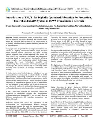
  • 2. International Research Journal of Engineering and Technology (IRJET) e-ISSN: 2395-0056 Volume: 09 Issue: 11 | Nov 2022 www.irjet.net p-ISSN: 2395-0072 © 2022, IRJET | Impact Factor value: 7.529 | ISO 9001:2008 Certified Journal | Page 657 The new substation designs take the latest equipment and technologies, applies them to substations in new and innovative ways that benefit the environment, DEWA and the community. II.DIGITAL SUBSTATIONS: FACTS VS MYTHS A full digital substation by definition includes low power instrument transformers (LPIT’s) also known as non- conventional instrument transformers (NCIT’s). These NCIT’s are connected to merging units, which perform analogue to digital conversion, applies a time stamp in order for the sampled values to be transmitted over an ethernet network. However, looking carefully at the concept of a digital substation, it is evident that since the NCIT’s are analogue devices that produce an analogue sinusoidal output, these systems are no more digital than conventional instrument transformers. The fact remains that substations transport power which is the product of voltage and current which are analog quantities both at primary and at secondary levels. We can therefore conclude that the term full digital substation is somewhat misleading. A. Comparison of NCIT Vs. Conventional CT In full digital substations non-conventional instrument transformers for measuring current are either a rogowski coil or optic sensor both of which are analog systems as shown in Figure1. These NCIT’s transfer analog quantities in proportion to the measured primary quantities to merging units (MU) which perform analog to digital (A to D) conversion much the same as conventional IED’s which already have built in A to D converters based on 1 amp input rating. The significant different appears at the output of the merging unit which transmits the measured data through ethernet. This is where the system becomes complex since ethernet does not have a definite or a fixed data transmission time. This is unacceptable for protection systems, which will become unstable due to measurement misalignment. The merging units therefore need to time tag each sample before transmitting. Since the IED’s are sampling at about 8kHz this amounts to a very large amount of data being transmitted for the 3phases plus neutral for currents and voltages from each merging unit. This data is transmitted through the process bus which in turn has the effect of slowing the ethernet speed. The additional cost, complexity, additional components with the obvious adverse impact on reliability would logically be implemented if there were some significant benefits. The claimed benefit is that NCIT’s produce a more linear and accurate measurement, which may be true if there was an identified reason why the conventional system was not adequate. Since protection IED’s have very advanced filtering and algorithms capable of maintaining optimum performance even with significant nonlinearity or saturation during faults – this advantage is negligible in almost all applications. For most applications it therefore becomes evident that the use of merging units is unwarranted and are an additional equipment required to be used that reduces overall reliability and availability of the power system. AnalogmA Analog1A Rogowski Coil NCIT Conventional CT Merging Unit Ethernet Switch Both systemsuseanalog measurement through an A to D converter. A to D converter isbuilt in Process Bus Fig1: Comparison of conventional CT vs Rogowski coil NCIT Non-conventional instrument transformers for all substation equipment such as bushing CT, Reactor internal CT and transformer neutral CT are not available especially for applications which are immersed in oil. This makes a full digital substation using all NCITs not possible. In DEWA a typical 132/11KV substation has 71 x 11kV bays which would result in a large number of merging units and a large amount of data on the process bus. The additional cost, complexity and the fact that OEM’s are unable to provide a consistent solution makes this option impractical considering that there is no benefit to the power system. B. Reliability of NCIT Vs. Conventional CT A quick comparison of NCIT with conventional CTs is as shown in table below. A NCITI requires a matching merging unit which needs to be considered as part of the measuring system when compared to a conventional CT which does not require additional components in order to connect to IED’s. It is evident that NCIT does have several disadvantages over conventional CTs in terms of mean time between failure (MTBF), performance, life expectancy etc. This is a separate
  • 3. International Research Journal of Engineering and Technology (IRJET) e-ISSN: 2395-0056 Volume: 09 Issue: 11 | Nov 2022 www.irjet.net p-ISSN: 2395-0072 © 2022, IRJET | Impact Factor value: 7.529 | ISO 9001:2008 Certified Journal | Page 658 subject and the details are not covered in this paper; however, it is evident that use of NCIT/sensors with merging units does not offer any great advantages towards substation digitization as shown in Table-1. Table-1 Conventional CT Vs NCIT Description Conventional CT Sensor + Merging Unit (NCIT) Life expectancy > 40 years 20 years Mean time between failures (MTBF) 1,506,939 500 Replacement strategy Not required May require new GIS Consequence of failure 1 x protection out Feeder + Busbar prot. + Control out Probability of interruption Low High Performance Medium High Advantage Reliability Claim of full digital III. DIGITALLY OPTIMIZED SUBSTATION DESIGN DEWA took the initiative to review the digital substation concept and developed an innovative digitally optimized substation (DOSS) design. The new design retains the proven reliable conventional instrument transformers and utilizes the most practical and beneficial digital substation concepts of process & station bus. The DOSS design utilizes the latest smart technology available in intelligent electronic devices (IED’s) which allows customizing and optimizing the configuration of the control and protection systems in substations while reducing the number of auxiliary relays and components. This approach ultimately achieves the best- engineered solution whilst achieving higher reliability, cost reduction and lower carbon footprint. The key features of the DOSS design are: ď‚· Consistent substation design irrespective of the contractors/ OEMs. ď‚· More efficient design approval process for new substation projects. ď‚· Reduction in time required for project design approvals, testing & commissioning. ď‚· Additional benefits such as reduction of maintenance cost, ease of operation and simplification of the substation design. ď‚· Using conventional instrument transformers ensures that protection and control systems can be refurbished in future without the risk of needing to replace instrument transformers or possibly switchgear. The digitally optimized substation simplified architecture is shown in Figure-2. Switches SubstationHMI Station B us Copper Hardwiring IE C61850 GOOS E IE C61850 GOOS E Bay-1 BCPU1 Bay-n BCPU1 Bay-1 BCPU2 Bay-n BCPU2 GISSwitchgear Status& Alarms Conventional CT / VT Equipment Sensor Data A. The Basis of Design Optimization Optimization of control and protection system considered the following main aspects: ď‚· Protection & Control functions are integrated in single Intelligent Electronic Device (IED) ď‚· Hard-wired interlocks replaced with digital signals (IEC61850 GOOSE signals over process bus). ď‚· Electromechanical relays replaced with digital functions. ď‚· Reduction or elimination of CTs. ď‚· Integrated busbar and feeder backup protections for 11kV network. ď‚· Integrated Tap Change Controller (AVR). ď‚· Removal of 24 x metering units on 11kV. ď‚· Elimination of external DFR devices by utilizing the inbuilt fault recorder capabilities in IEDs. Figure-2: Simplified DOSS Architecture
  • 4. International Research Journal of Engineering and Technology (IRJET) e-ISSN: 2395-0056 Volume: 09 Issue: 11 | Nov 2022 www.irjet.net p-ISSN: 2395-0072 © 2022, IRJET | Impact Factor value: 7.529 | ISO 9001:2008 Certified Journal | Page 659 ď‚· Each bay shall have two independent and redundant protection and control systems. ď‚· Two independent auxiliary DC systems for BCPU-1 & BCPU-2, to avoid common mode failure. ď‚· Protection schemes engineered to produce efficient designs with minimum number of auxiliary components. ď‚· Standardization of SCADA alarm lists with reduced number of alarms to the master control station. B. Details of Design Optimization for a Typical 132kV Feeder Bay For a typical 132kV feeder bay the existing conventional SS design and new digitally optimized SS design are as shown in Figure-3. Integrated Protection,BCU, SynchCheck, VSSandDFRin bothBCPUs Digital Busbar Protectiondoes not requirea separateCT for theCheckZone. Figure-3: Feeder bay design in conventional & DOSS design The protection and control designs for a typical feeder bay in conventional and new DOSS designs are compared in Table-2. Table-2: Comparison of Feeder bay design in conventional & DOSS design Application Existing Conventional SS Design Digitally Optimized SS Design Bay Protection Main-1 Protection (M1FP) Bay Control & Protection Unit-1 (BCPU1) Main-2 Protection (M2FP) Bay Control & Protection Unit-2 (BCPU2) Bay Control Bay Control Unit (BCU) Not Applicable (Integrated to BCPU1, 2 and Respective CT core eliminated) Fault recorder DFR Busbar protection High Impedance Main-1 Protection (M1BZP) Low Impedance Main-1 Protection (M1BZP) Low Impedance Main-2 Protection (M2BZP) Low Impedance Main-2 Protection (M2BZP) DOSS designs include integrated control & protection panels (CPP) instead of separate protection and control LCC panels. A comparison of existing and new panels are as shown in Figure-4. Existing132kVFeeder ProtectionPanel Existing132kVFeeder LCCPanel Bay Controller BCPU2 BCPU1 All Protection, Bay Control, Voltage Selection Scheme, DFR& Interlocks are integrated into new BCPU’s with complete redundancy. New132kVControl& Protection Panel (CPP) Main1 Prot.Relay Main2 Prot.Relay Figure-4: Feeder bay panels between conventional and DOSS design
  • 5. International Research Journal of Engineering and Technology (IRJET) e-ISSN: 2395-0056 Volume: 09 Issue: 11 | Nov 2022 www.irjet.net p-ISSN: 2395-0072 © 2022, IRJET | Impact Factor value: 7.529 | ISO 9001:2008 Certified Journal | Page 660 Accordingly, similar optimizations are done for all 132kV and 11kV bays in the new DOSS design. As per the new BCPU and BMP functionality, the protection & control IED’s are prequalified and approved after successful laboratory testing. The approved BCPU, BMP IEDs for some of the applications are as shown in below Table-3. Table-3: Prequalified BCPU, BMP IEDs for DOSS SS Voltage Level Typical Bay Application IED Make IED Type 132kV Feeder BCPU1 / BCPU2 Siemens 7SL87 SEL 411L Hitachi RED670 132kV Bus Coupler BCPU1 / BCPU2 Siemens 7SJ85 SEL 451 Hitachi REC670 132kV IDT Transformer BCPU1 / BCPU2 Siemens 7UT85 SEL 487E Hitachi RET670 11kV Feeder, Incomer & Capacitor Feeder BMP Siemens 7SJ85 SEL 451 Hitachi REC670 C. SCMS Architecture in new DOSS Design In the new DOSS design, the SCMS is completely redesigned and introduces virtual technologies. The number of SCMS components are greatly reduced whilst increasing reliability and redundancy. The SCMS architecture utilized in new DOSS design is as shown in Figure-5. Station Switch-A (Level-2) Station Switch-B (Level-2) LAN-A Field Switch Substation HMI NETWORK C02 -BCPU1 C09 -BCPU1 C04 -BCPU1 C05 -BCPU1 C06 -BCPU1 C07 -BCPU1 C08 -BCPU1 C03 -BCPU1 M1BZP-R M1BZP-Y M1BZP-B FDR RXR-1 M1RP FDR RXR-2 M1RP 1 2 3 4 5 6 7 8 9 10 11 12 13 14 15 16 LAN-B Field Switch 1 2 3 4 5 6 7 8 9 10 11 12 13 14 15 OTS Panel-1 M2BZP-R M2BZP-Y M2BZP-B 132kV Digitally Optimized Substation – SCMS Topology C02 -BCPU2 C03 -BCPU2 C04 -BCPU2 C05 -BCPU2 C06 -BCPU2 C07 -BCPU2 C08 -BCPU2 C09 -BCPU2 FDR RXR-1 M2RP FDR RXR-2 M2RP Metering System (EMVS) Common BCU-1 OTS Panel-2 Thin Client Remote Access, Retrieval of Digital Fault Records and DataManagement System for Substation IED s (Centralized Cloud Storage & Engineering Workstation ) IT/ OT PERIMETER DEWA - IT Network Dashboard / Mobile Viewers IED Configuration / setting Users DFR Users (TPD & RTO) OTS DC-1 OTS DC-2 EMVS- 1 EMVS- 2 TCC-1 DCC-1 DCC-2 TCC-2 Notes: 1. This concept topology does not constitute a detailed design. 2. Substation Server includes Security Systems, SCMS, EWS and local storage. GPS CLOCK SCMS Panel-1 SCMS Panel-2 Substation Server & Gateway 1 (Virtual Security) (Virtual Security) 17 18 19 20 21 22 23 24 16 17 18 19 20 21 22 24 23 15 Substation Server & Gateway 2 DC 1 Charger Controller DC3 Charger Controller DC 2 Charger Controller (Future) C01 -BCPU1 (Future) C01 -BCPU2 Common BCU-2 11kV Bus 1 Loop 11kV BB CU1 11kV BB CU2 11kV BB CU3 F01-BMP F02-BMP F22-BMP F23-BMP 11kV Bus 3 Loop F48-BMP F49-BMP F70-BMP F71-BMP Busbar Protection Central Units 11kV Bus 2 Loop F24-BMP F25-BMP F46-BMP F47-BMP 11kV Switchgear Figure-5: SCMS architecture in DOSS design D. Standardization of DOSS Design Standardization in DOSS design achieved by preparing standard design documents by DEWA and including them as part of tender documents for contractor’s strict compliance. The following are the standard design documents: ď‚· Control and Protection specification. ď‚· SCMS technical specification. ď‚· DC technical specification. ď‚· Metering technical specification. ď‚· Conceptual protection single line diagrams, trip logics and control & interlock logics for all the typical bays. ď‚· Control and protection panel schematic and general arrangements drawings. ď‚· Substation DC system single line diagrams. ď‚· Substation DC chargers schematic and general arrangement drawings. ď‚· Test terminal block standard terminal arrangements. ď‚· Master station SCMS signal list with standard IEC61850 signal address. ď‚· Standard CT & VT parameters for all bays and all applications. ď‚· BCPU/ BMP IEDs specific wiring templates for each make and application. In addition to above mentioned standard design documents, pre-qualified manufacturers were also provided to the contractors to select the approved vendors.
  • 6. International Research Journal of Engineering and Technology (IRJET) e-ISSN: 2395-0056 Volume: 09 Issue: 11 | Nov 2022 www.irjet.net p-ISSN: 2395-0072 © 2022, IRJET | Impact Factor value: 7.529 | ISO 9001:2008 Certified Journal | Page 661 ď‚· Approved IEDs list. ď‚· Approved protection and control component list. ď‚· Approved energy meters list. ď‚· Approved CT and VT manufacturers list. ď‚· Approved panel manufacturers list. ď‚· Approved DC system manufacturers list. E. Digitally Optimized SS Design – Benefits The new innovative digitally optimized substation design provides significant benefits to DEWA as a utility. The new design for 132/11kV substations includes the following advantages: ď‚· Protection & control functions are integrated into a single IED (BCPU1/2): Reduction of 15 IEDs, redundancy in control functions and 18 x control and protection panels removed. ď‚· Hard wired interlocks are replaced with peer-peer GOOSE digital signals: Over 100km of copper cabling eliminated. ď‚· All electromechanical relays replaced with digital systems: Over 8000 devices removed. ď‚· Reduction in the number of current transformers: Total 258 units removed. ď‚· Integrated busbar and feeder backup protection for 11kV network. ď‚· Integrated tap change controller (AVR) into BMP IEDs: Panel with 3 x controllers removed (digitized). ď‚· Removal of 24 x metering units on 11kV. ď‚· Integrated digital fault recorders (DFR’s): 3 x DFR panels removed. ď‚· Optimized SCMS system: 4 x SCMS panels, 5 x computers, 2 x monitors, 20 x network switches, 196 fiber optic cables, 4 x fiber optic patch panels, 1 x GPS clock removed. ď‚· Virtual security, role based remote engineering access through virtual machine is achieved. The summary of removed equipment as part of the 132/11kV design optimized SS are as shown in Table-4. Table-4: Summary of removed equipment in DOSS SS S.No. Equipment Description of Change Quantity of Removed equipment 1 132kV GIS Reduce 13 x Sets = 39 CT's 39 2 132kV Feeders Remove 3 x 132kV Protection Panels 3 3 132kV IDT's Remove 3 x 132kV Protection Panels 3 4 132kV Bus Coupler Remove 1 x 132kV Protection Panel 1 5 132kV LCC Reduce 6,707 x components (Aux relays, timers, terminals, mcb's, switches etc.) 6707 6 11kV Feeder with Metering Meters removed and CT's for metering are retained. 255 7 11kV Feeder without Metering Optimized with reduced CT's and components 672 8 11kV Cap Bank Reduced Capacitor Bank Protection relay and integrated into BMP. 102 9 11kV Incomer Check Zone relay removed, AVR function integrated into BMP. 81 10 11kV Bus Sections Reduced CT's and several components digitized 59 11 11kV Busbar Remove High Impedance scheme and implement Low Impedance BBP with integrated 11kV Feeder Backup protection. Reduce 73 x sets of CT's 3 12 LVAC Remove 34 components including High Impedance REF & CT's 34 13 SCMS SCMS panels & components 232 14 AVR Remove 1 x AVR panels and equipment’s 4 15 Digital Fault Recorder (DFR) Remove 3 x DFR panels and equipment’s 3 Total 8198
  • 7. International Research Journal of Engineering and Technology (IRJET) e-ISSN: 2395-0056 Volume: 09 Issue: 11 | Nov 2022 www.irjet.net p-ISSN: 2395-0072 © 2022, IRJET | Impact Factor value: 7.529 | ISO 9001:2008 Certified Journal | Page 662 Additionally, the new design will support DEWA’s vision and environmental goals. ď‚· The reduction in carbon emissions approximately 37 tons per year for 132/11kV substation due to annual energy saving of 53MWH. ď‚· Reduction in substation building size by 133m2. ď‚· Savings of 7 million AED per substation due to reduced equipment. ď‚· The new design utilizes, control and protection panels (CPP) developed in the UAE along with local manufacturers. IV. CONCLUSION The DOSS design selects the best technologies available, combines it with best design practices to achieve the industry leading optimized substation design. The innovative DOSS design concept can be implemented in other organizations globally, which have the same business portfolio (electricity supply), and this will positively influence our responsibility to support the sustainable development goals and protect the environment. V. REFERENCES [1] John bettler, Jesse Silva, Dan Morman, “Case Studies of IEC61850 Process Bus Systems Using GOOSE and Sample Values: Recent Installations and Research”, proceedings of the 74th Annual Georgia Tech Protective Relaying Conference, April-2021. [2] Stefan Meier, Thomas Werner, “Performance considerations in digital substation applications” white paper presented at PAC World UK 2015. [3] Greg Rzepka, Scott Wenke, Sarah Walling, “Choose Simplicity for a Better Digital Substation Design”, 70th Annual Conference for Protective Relay Engineers, Texas, April-2017. [4] Qinccui Fu, Jianyun Chen, “Design of Experiment Platform for Digital Substation Based on IEC61850”, 5th International Conference on Computer Science and Network Technology (ICCSNT)-2016 [5] Topolsky D.V., Topolskaya I.G., Topolsky N.D, “Development of an Intelligent Measuring System for Digital Substations”, International Multi conference on Industrial Engineering and Modern Technologies (FarEastCon)-2018. [6] E.V. Solomin, D.V. Topolskiy, N.D. Topolskiy, “Integration of Adaptive Digital Combined Current and Voltage Transformer into Digital Substation Ethernet Grid”, International Siberian Conference on Control and Communications (SIBCON)-2015.