Ijtra130512
•
1 gefällt mir•473 views

ANALYSIS OF EXPERIMENTAL VALUES OF BEND LOSS BY OTDR

Empfohlen
Empfohlen
Weitere ähnliche Inhalte
Was ist angesagt?
Was ist angesagt? (19)
Andere mochten auch
Andere mochten auch (20)
Ähnlich wie Ijtra130512
Ähnlich wie Ijtra130512 (20)
Mehr von International Journal of Technical Research & Application
Mehr von International Journal of Technical Research & Application (20)
Kürzlich hochgeladen
Kürzlich hochgeladen (20)
Ijtra130512
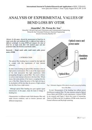
- 1. International Journal of Technical Research and Applications e-ISSN: 2320-8163, www.ijtra.com Volume 1, Issue 3 (july-August 2013), PP. 25-30 ANALYSIS OF EXPERIMENTAL VALUES OF 25 | P a g e BEND LOSS BY OTDR Akanchha1, Mr. Pawan Kr. Sen.2 Akanchha1 (M.tech Final year), Electronics and Communication Engineering Pawan Kr.Sen 2(Assistant Professor), Electrical Engineering. Invertis University Bareilly UP. Abstract- In this paper, showed the measurement of bend loss in single mode fiber and multimode fiber in different bend radius at different wavelength by using OTDR and compares the value of bend loss of single mode fiber with standard paper and also performed reduce the bend loss at particular radius . Keywords – Single mode cable, multi mode cable, power meter, OTDR. I. INTRODUCTION The optical fiber bending loss is created by that light fail to comply with this requirement of total internal reflection. In other word, bending an optical fiber introduce a loss in light power or attenuation. This is one of the major causes of the total attenuation that light experiences while propagating through an optical fiber. The result is failure to achieve total internal reflection in the bent fiber .Which means that some portion of the beam is escaping from the core of the fiber .Hence the power of the light arriving at its destination will be less than the power of light emitted into the fiber from a light source. Although optical fiber bending loss goes against signal transmission. In this paper, study the trend of change of bending loss Characteristics in different mode field diameter fiber and under diverse condition, such as tension /pressure and different temperature. Fig.1. Schematic diagram of the optical set-up for measuring bending loss of the fiber. In real, Measurement of the bending loss reflects power distribution in optical fiber. We may measure using by Optical Power Meter and OTDR in such experiments. I choose OTDR in my research and Figure 2 shows the course of measuring. There is OTDR at the left. In addition, OTDR works, based on Fresnel reflection and Rayleigh scattering.
- 2. International Journal of Technical Research and Applications e-ISSN: 2320-8163, www.ijtra.com Volume 1, Issue 3 (july-August 2013), PP. 25-30 26 | P a g e II. THEORY We first considered the bending loss of different radius at different angle of single and multimode fiber. In single mode has a narrow core so one mode can pass and multimode fiberhas large core compare to single mode. So different light ray can be pass and compare the bend loss of single mode fiber with multimode fiber at different angle. I analyzed the relationship between them. Bend loss is related to bend radius and conduction laser wavelength. Measure optical fiber was G.652. So parameters are (i) Core radius, a = 14.2 μm, n1 = 1.50047, n2=1.5. (ii) The core radius, a = 14.3μm, n1 = 1.50047 n2 = 1.5, R = 100 mm. For single mode fiber we change the wavelength and radius the bend of the cable. This table-1 show bends loss of single mode fiber at wavelength 1310nm. Table No. 1 Bend radius r mm Circum- Ference Ccm The no. of laps n Total loss in db The loss of each lap So The loss of per unit length So/c 5 3.1416 1 2.236 1.118 .356 6 3.7699 1 0.998 0.333 .088 7 4.3982 1 0.935 0.234 .053 8 5.0265 1 0.378 0.063 .013 9 5.6549 4 0.316 0.045 .008 10 6.2832 8 0.018 0.003 .048 12 7.5398 14 -0.07 -0.008 -.001 13 8.1681 25 -0.011 -0.001 -0.012 Being based on these parameters, we can draw two charts that showed the dependence of bend loss on both radius and wavelength. Comparing measurements with the theoretical value. We can come to a conclusion that the errors were not large, as in Figure1 showed. Fig. 1-comparing the value of the academic and practical on the bend loss.
- 3. International Journal of Technical Research and Applications e-ISSN: 2320-8163, www.ijtra.com Volume 1, Issue 3 (july-August 2013), PP. 25-30 27 | P a g e Fig.2- the bend loss of two wavelength Show the bend loss of power meter shined the lasers with the wavelength of 1550nm and 1310nm. There were bending loss measurement dates of them, as Figure 5 showed. As can be seen from the graph, losses at a wavelength of 1550nm were greater than at 1310nm under the same bending radius. two wavelength. Now comparing the bend loss of single mode fiber in different radius with the standard table. Table No-2 Bend radius r mm Circum-ference The no. of laps n Total loss in db The loss of each lap So The loss of per unit length So/c 5 3.1416 1 7.453 7.453 2.376 6 3.7699 1 5.344 5.344 1.14183 7 4.3982 1 2.653 2.653 0.6035 8 5.0265 1 0.995 0.995 0.198 9 5.6549 4 2.235 0.5587 0.0988 10 6.2832 8 3.141 0.3926 0.0625 11 6.9115 10 0.876 0.0876 0.0127 12 7.5398 14 1.063 0.0759 0.0101 13 8.1681 25 0.938 0.0375 0.0046 14 8.7965 40 1.196 0.0299 0.0034 Here can be seen in this table error is large compare to table no-1. We can come to conclusion error is not large with increase no. of radius .So, this table use for verify the previous table of measurement of bend loss in different radius. Table No-3 This table show of bend loss of multimode fiber in different radius by using wavelength 1310 nm. Bend radius r mm Circum-ferece The no. of laps n Total loss Sdb The loss of each lap So The loss of per unit length So/c 5 3.1416 1 .500 .500 0.159 6 3.7699 1 .480 .480 0.128 7 4.3982 1 .200 .200 0.046 8 5.0265 1 .150 .150 .030 9 5.6549 4 .130 .520 0.092 10 6.2832 8 .100 .800 0.127 11 6.9115 10 .090 0.900 .130 12 7.5398 14 .007 0.098 0.013 13 8.1681 25 .003 0.075 .009 14 8.7965 40 .001 0.040 0.005 15 9.4248 50 -0.010 0.500 -0.053
- 4. International Journal of Technical Research and Applications e-ISSN: 2320-8163, www.ijtra.com Volume 1, Issue 3 (july-August 2013), PP. 25-30 15 13 0 0.002 0.004 0.006 0.008 0.01 28 | P a g e This table show of bend loss of multimode fiber in different radius by using wavelength 1550 nm. Table No-4 Bend radius r mm Circum- Ference c cm The no. of laps n Total loss Sdb The loss of each lap So The loss of per unit length 5 3.1416 1 0.130 0.130 0.041 6 3.7699 1 0.110 0.110 0.029 7 4.3982 1 0.080 0.080 0.018 8 5.0265 1 0.040 0.040 0.008 9 5.6549 4 0.020 0.080 0.014 10 6.2832 8 0.010 0.080 0.013 11 6.9115 10 -0.02 -0.20 -0.029 12 7.5398 14 -0.11 -1.54 -0.205 13 8.1681 25 -0.15 -3.75 -0.199 We can see at both table no.3 and 4 that errors are large at the wavelength 1550 nm. That means if increase wavelength than bend loss will be increase with bend radius. Show that losses at a wavelength of 1550 nm greater than at 1310 nm under the same bending radius. Loss can be reduced at a particular radius when output power goes to same input power or approximately. Being based on these parameters, we can draw two charts that showed the dependence of bend loss on both radius and wavelength. Comparing measurements with the theoretical value. We can come to a conclusion that the errors were not large. 50 48 20 60 50 40 30 20 10 0 Fig. 3 -comparing the value of the academic and practical on the bend loss. 450 400 350 300 250 200 150 100 50 0 0 0.002 0.004 0.006 0.008 0.01 Fig. 4 - the bend loss of two wavelength I have got a normal curve measuring by OTDR.as shown as Figure 5.
- 5. International Journal of Technical Research and Applications e-ISSN: 2320-8163, www.ijtra.com Volume 1, Issue 3 (july-August 2013), PP. 25-30 29 | P a g e - Fig.5- wave form of straight fibe In figure ( 5) show curve by OTDR when cable has no bend, here can be seen cable goes to straight. In figure ( 6) cable bend at below 5mm than o/p get to distorted that means if cable bend at below 5mm than o/p power get more losses. In figure ( 7) when cable bend at 11 mm radius than o/p power get less loss .It can be measure by Power meter. It proved that loss can be reduced at particular radius with the help of power meter and OTDR .if cable bend at below 5 mm than output power get more loss. So it has limitation cable can not be bend at below 5 mm. Fig.6-The loss line in bend radius at 8 mm. Fig 7- The loss line in bend radius at 11 mm III. CONCLUSION In this paper a study of bending loss of the fiber cable at diffrerent radius at different wavelength of single and multimode fiber.and reduce the bend loss of both fiber cable at 11mm for single mode and 12 mm for multimode
- 6. International Journal of Technical Research and Applications e-ISSN: 2320-8163, www.ijtra.com Volume 1, Issue 3 (july-August 2013), PP. 25-30 30 | P a g e fiber.Show the result calculate the bend loss about single mode and multimode and test proved that the bend loss varied inversely as the bending radius with the wavelength being constant,At the same time ,Some radius of bend cable by power meter ,when having a bend in different positions . So comparing the measured curve that was got in real time with curves. ACKNOWLEDGEMENT We would like to thanks our honorable teacher a Pawan Kr. Sen. (Assistant Professor) Electrical Department Invertis University Bareilly for his great help and precious suggestions about this work. REFERENCE [1] Luc B.Jeunhomme. single-mode fiber optics principles and applications[M]. New York: printed in the united states of America, [2] Marcuse D. Bend loss of slab and fiber mode com puted with diffraction theory [J]. IEEE Journal of QE, 1993, 29(12):2957-296.. [3] Murakami Y.Bending losses of coated single mode optical fiber 1978(07). [4] Renner H. Bending losses of coated single-mode fibers, a simple approach 1992. [5] Marcuse D .Curvature loss formula for optical fibers 1976. [6] Micelles R W Nonlinear bent single-mode wave-guide as a simple all optical switch 1988. [7] SNYDER, A.W.: ‘Leaky-ray theory of optical waveguides of circular cross-section’, Appl. Phys., 1974, 4, pp. 273-98 [8] WINKLER, C., LOVE, J.D., and GHATAK, A.K.: ‘Power attenuation in bent parabolic-index slab and fiber waveguides’, Electron. Lett. 1978, 14, pp. 570- 571 [9] WINKLER, C., LOVE, J.D., and GHATAK, A.K.: ‘Loss calculations in bent multimode optical. Waveguide’s, Opt. Quantum Electron., 1979, 11, pp. 173-183. [10] SAIJONMAA, J.: ‘Beam-propagation analysis of loss in bent optical waveguides and fibers’, J. Opt. Soc. Am., 1983, 73, pp. BAETS, R., and LAGASSE, P.E.: ‘Loss calculation and design of arbitrarily curved integrated-optic waveguide’s, J. Opt. Soc. Am., 1983,73, pp. 177-182 [11] LEE, W.Y., LIN, J.S., and WANG, S.Y.: ‘A novel vertical AK directional coupler switch using liquid crystals’, J. Light wave Technol., 1995, 13, pp. 49-54 AKANCHHA is pursuing M.Tech in Electronic & Communication Engineering from Invertis University Bareilly UP. Her research areas interests are Optical fiber Communication system. Email- akkip9@gmail.com. Pawan Kr.Sen is an Assistant Professor in Electrical Engineering Department at Invertis University Bareilly UP.His research area interests are Power Electronics system.