Design and Analysis of Microstrip Patch Antenna with Optimization for Wireless Communication
•
2 gefällt mir•688 views

In this paper, design of conventional Rectangular patch Microstrip antenna has been proposed and its performance is analyzed. The design parameters of antenna are selected to achieve compact dimensions as well as best possible characteristics such as high gain, increased bandwidth with minimum return loss. Hence improved design has been demonstrated over elementary one. These antennas have been designed at 2.4GHz which enables its usage in wireless communication domain such as Wireless Local Area Network (WLAN). The antenna design and performance are analyzed using Ansoft HFSS software. These antennas can be used for many wireless communication systems.

Empfohlen
Weitere ähnliche Inhalte
Was ist angesagt?
Was ist angesagt? (20)
Andere mochten auch
Andere mochten auch (15)
Ähnlich wie Design and Analysis of Microstrip Patch Antenna with Optimization for Wireless Communication
Ähnlich wie Design and Analysis of Microstrip Patch Antenna with Optimization for Wireless Communication (20)
Mehr von ijsrd.com
Mehr von ijsrd.com (20)
Kürzlich hochgeladen
Kürzlich hochgeladen (20)
Design and Analysis of Microstrip Patch Antenna with Optimization for Wireless Communication
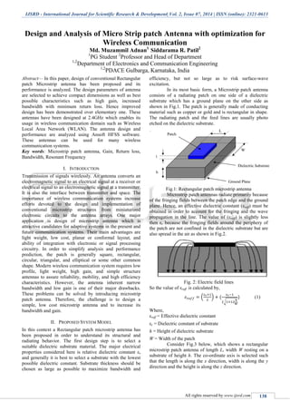
- 1. IJSRD - International Journal for Scientific Research & Development| Vol. 2, Issue 07, 2014 | ISSN (online): 2321-0613 All rights reserved by www.ijsrd.com 138 Design and Analysis of Micro Strip patch Antenna with optimization for Wireless Communication Md. Muzammil Adnan1 Siddarama R. Patil2 1 PG Student 2 Professor and Head of Department 1,2 Department of Electronics and Communication Engineering 1,2 PDACE Gulbarga, Karnataka, India Abstract— In this paper, design of conventional Rectangular patch Microstrip antenna has been proposed and its performance is analyzed. The design parameters of antenna are selected to achieve compact dimensions as well as best possible characteristics such as high gain, increased bandwidth with minimum return loss. Hence improved design has been demonstrated over elementary one. These antennas have been designed at 2.4GHz which enables its usage in wireless communication domain such as Wireless Local Area Network (WLAN). The antenna design and performance are analyzed using Ansoft HFSS software. These antennas can be used for many wireless communication systems. Key words: Microstrip patch antenna, Gain, Return loss, Bandwidth, Resonant Frequency I. INTRODUCTION Transmission of signals wirelessly. An antenna converts an electromagnetic signal to an electrical signal at a receiver or electrical signal to an electromagnetic signal at a transmitter. It is also the interface between transmitter and space. The importance of wireless communication systems increase efforts devoted to the design and implementation of conventional microstrip structures from miniaturized electronic circuits to the antenna arrays. One major application is design of microstrip antenna which is attractive candidates for adaptive systems in the present and future communication systems. Their main advantages are light weight, low cost, planar or conformal layout, and ability of integration with electronic or signal processing circuitry. In order to simplify analysis and performance prediction, the patch is generally square, rectangular, circular, triangular, and elliptical or some other common shape. Modern wireless communication system requires low profile, light weight, high gain, and simple structure antennas to assure reliability, mobility, and high efficiency characteristics. However, the antenna inherent narrow bandwidth and low gain is one of their major drawbacks. These problems can be solved by introducing microstrip patch antenna. Therefore, the challenge is to design a simple, low cost microstrip antenna and to increase its bandwidth and gain. II. PROPOSED SYSTEM MODEL In this context a Rectangular patch microstrip antenna has been proposed in order to understand its structural and radiating behavior. The first design step is to select a suitable dielectric substrate material. The major electrical properties considered here is relative dielectric constant εr and generally it is best to select a substrate with the lowest possible dielectric constant. Substrate thickness should be chosen as large as possible to maximize bandwidth and efficiency, but not so large as to risk surface-wave excitation. In its most basic form, a Microstrip patch antenna consists of a radiating patch on one side of a dielectric substrate which has a ground plane on the other side as shown in Fig.1. The patch is generally made of conducting material such as copper or gold and is rectangular in shape. The radiating patch and the feed lines are usually photo etched on the dielectric substrate. Fig.1: Rectangular patch microstrip antenna Microstrip patch antennas radiate primarily because of the fringing fields between the patch edge and the ground plane. Hence, an effective dielectric constant (εreff) must be obtained in order to account for the fringing and the wave propagation in the line. The value of (εreff) is slightly less then εr because the fringing fields around the periphery of the patch are not confined in the dielectric substrate but are also spread in the air as shown in Fig.2. Fig. 2: Electric field lines So the value of εreff is calculated by, ( ) √ (1) Where, εreff = Effective dielectric constant εr = Dielectric constant of substrate h = Height of dielectric substrate W = Width of the patch Consider Fig.3 below, which shows a rectangular microstrip patch antenna of length L, width W resting on a substrate of height h. The co-ordinate axis is selected such that the length is along the x direction, width is along the y direction and the height is along the z direction.
- 2. Design and Analysis of Micro Strip patch Antenna with optimization for Wireless Communication (IJSRD/Vol. 2/Issue 07/2014/033) All rights reserved by www.ijsrd.com 139 Fig. 3: Microstrip patch antenna The dimensions of patch are obtained by using the formula give below ( ) ( ) (2) For a given resonance frequency fr , the effective length is (3) Hence length of patch is calculated, (4) For efficient radiation, the width W is (5) Microstrip patch antenna can be fed by variety of methods and the feed technique used here is co-axial feed also known as probe feed. In co-axial feed, the inner conductor of the coaxial connector extends through the dielectric and is soldered to the radiating patch, while the outer conductor is connected to the ground plane. The main advantage of this type of feeding scheme is that the feed can be placed at any desired location inside the patch in order to match with its input impedance. This feed method is easy to fabricate and has low spurious radiation. However, its major disadvantage is that it provides narrow bandwidth and is difficult to model since a hole has to be drilled in the substrate. Fig. 4: Co-axial feed technique The feed location is calculated by, √ (6) Where, (7) (8) Design Algorithm:- The Microstrip patch antenna proposed above is designed in following steps: (1) Select a solution type. (2) Create substrate. (3) Add a Ground plane. (4) Create a cut. (5) Complete the ring. (6) Add patch. (7) Create Co-ax and Co-ax pin. (8) Define port. (9) Add probe. (10)Define Air- Box. (11)Assign required frequency and verify the result. III. SIMULATION RESULTS A. Antenna 1 design (Rectangular patch): Symbol Parameter Value fr Resonance frequency 2.4GHz εr di-electric constant (RT Duroid5880 substrate) 2.2 h Height of substrate 1.6mm L Length of patch 42.14mm W Width 42.14mm Table 1: Antenna details Fig. 5: Co axial feed (Rectangular patch)
- 3. Design and Analysis of Micro Strip patch Antenna with optimization for Wireless Communication (IJSRD/Vol. 2/Issue 07/2014/033) All rights reserved by www.ijsrd.com 140 Fig. 6: 3-D Polar plot of Gain distribution Fig. 7: Return Loss curve Return loss= -14.518dB. Resonance frequency= 2.28GHz. Bandwidth= 48.7MHz. B. Antenna 2 design (H shaped patch) Symbol Parameter Value fr Resonance frequency 2.4GHz εr di-electric constant (RT Duroid5880 substrate) 2.2 h Height of substrate 1.6mm L Length of patch 42.14mm W Width 42.14mm Table 2: Antenna details Fig. 8: H shaped patch Fig. 9: 3-D Polar plot for gain distribution Fig. 10: Return loss curve Return loss= -20.877dB. Resonance frequency= 2.44GHz. Bandwidth= 100MHz. IV. CONCLUSION The Rectangular Micro strip Patch antenna has been analyzed. From the result of HFSS simulation, it has been observed that the bandwidth is increased by 51.3% and also giving much desirable resonance. The antennas proposed can be built and measured to compare the real results with those obtained from the simulations as a future work. Possible applications of this antenna include RFID, UHF applications. REFERENCES [1] The antenna tutorial website. http://www.antenna- theory.com/antennas. [2] Constantine A. Balanis. Antennas Theory - Analysis and Design. 3rd Edition. John Wiley & Sons, Inc, 1997. [3] John D. Kraus. Antennas. 2nd Edition. McGraw Hill International, 1988. [4] W.L Stutzman and G.A Thiele. Antenna Theory and Design. John Wiley & Sons, Inc, 1998. [5] Suprlyo Day, C. K. Aanandan, P. Mohanan, and K. G. Nair, “A New Broadband Circular Patch Antenna”, Microwave and Optical Technology Letters, Vol. 7, No. 13, pp.604-606, September 1994. [6] K. L .Wong, C. L. Tang, and H. T. Chen, “A compact meandered circular microstrip antenna with a shorting pin,” Microwave and Optical Technology Letters, 15, 147–149, June 20, 1997. [7] Tae-Hyun Kim, Dong-Chul Park, “Compact dual- band antenna with double L-slits for WLAN 1.00 1.50 2.00 2.50 3.00 3.50 4.00 4.50 5.00 Freq [GHz] -17.50 -15.00 -12.50 -10.00 -7.50 -5.00 -2.50 0.00 dB(St(Circle1_T1,Circle1_T1)) HFSSDesign1XY Plot 1 ANSOFT m2 Curve Info dB(St(Circle1_T1,Circle1_T1)) Setup1 : Sweep Name X Y m2 2.2800 -14.5180 1.00 1.50 2.00 2.50 3.00 3.50 4.00 4.50 5.00 Freq [GHz] -35.00 -30.00 -25.00 -20.00 -15.00 -10.00 -5.00 0.00 dB(St(Circle1_T1,Circle1_T1)) HFSSDesign1XY Plot 1 ANSOFT MY1:-10.0270 m 2 Curve Info dB(St(Circle1_T1,Circle1_T1)) Setup1 : Sw eep fx='7.5mm' fy='7.5mm' dB(St(Circle1_T1,Circle1_T1)) Setup1 : Sw eep fx='8mm' fy='7.5mm' dB(St(Circle1_T1,Circle1_T1)) Setup1 : Sw eep fx='8.5mm' fy='7.5mm' dB(St(Circle1_T1,Circle1_T1)) Setup1 : Sw eep fx='9mm' fy='7.5mm' dB(St(Circle1_T1,Circle1_T1)) Setup1 : Sw eep fx='7mm' fy='8mm' dB(St(Circle1_T1,Circle1_T1)) Setup1 : Sw eep fx='7.5mm' fy='8mm' dB(St(Circle1_T1,Circle1_T1)) Setup1 : Sw eep fx='8mm' fy='8mm' Name X Y m 2 2.4400 -20.8770
- 4. Design and Analysis of Micro Strip patch Antenna with optimization for Wireless Communication (IJSRD/Vol. 2/Issue 07/2014/033) All rights reserved by www.ijsrd.com 141 operations”, IEEE Antennas and Wireless Propagation Letters, Vol. 4, Page(s): 249 – 252, 2005 [8] V. R. Gupta and Nisha Gupta, “Two compact Microstrip patch antennas for 2.4.GHz band-A comparison,” Microwave and Optical Technology letters, pp29-31, November 2006. [9] A. S. N. Khan, J. Hu, J. Xiong, and S. He, “Circular fractal monopole antenna for low VSWR UWB applications”, Progress in Electromagnetic Research Letters, Vol. 1, pp. 19–25, 2008. [10]Pritam Singha Roy, Rudra Prasad Biswas, “Optimization with I-slotted Microstrip Patch Antenna for wireless communication”, IJAIEM, Volume 2, Issue 4, April 2013, Page(s): 16-20.