SlideShare ist ein Scribd-Unternehmen logo
1 von 74
UNIT V
COMMUNICATION ENGINEERING
5.1 TELECOMMUNICATION SYSTEM
Communication is a data transmitting technique in a format that utilizes continuous
signals to transmit data including voice, image, video, electrons etc. An analog signal is a
variable signal continuous in both time and amplitude which is generally carried by use of
modulation. Analog circuits do not involve quantization of information unlike the digital
circuits and consequently have a primary disadvantage of random variation and signal
degradation, particularly resulting in adding noise to the audio or video quality over a distance.
Data is represented by physical quantities that are added or removed to alter data.
Analog transmission is inexpensive and enables information to be transmitted from point-to-
point or from one point to many. Once the data has arrived at the receiving end, it is converted
back into digital form so that it can be processed by the receiving computer. Analog
communication systems convert (modulate) analog signals into modulated (analog) signals.
Communication systems convert information into a format appropriate for the transmission
medium. The Block diagram of a communication system is given below:
Fig.5.1 Communication System Block Diagram
The Source encoder converts message into message signal or bits. The Transmitter
converts message signal or bits into format appropriate for channel transmission (analog/digital
signal). The Channel introduces distortion, noise, and interference. Receiver decodes received
signal back to message signal. Source decoder decodes message signal back into original
message.
Source
(Voice, Code,
Picture, Data)
Transmitter Channel or
Medium Destination
Receiver
Noise signal
5.2 Basic Electrical and Electronics Engineering
Transmitter and Modulation
Each system contains a transmitter. This consists of a source of electrical energy,
producing alternating current of a desired frequency of oscillation. The transmitter contains a
system to modulate (change) some property of the energy produced to impress a signal on it.
This modulation might be as simple as turning the energy on and off, or altering more subtle
properties such as amplitude, frequency, phase, or combinations of these properties. The
transmitter sends the modulated electrical energy to a tuned resonant antenna; this structure
converts the rapidly changing alternating current into an electromagnetic wave that can move
through free space (sometimes with a particular polarization).
Amplitude modulation of a carrier wave works by varying the strength of the
transmitted signal in proportion to the information being sent. For example, changes in the
signal strength can be used to reflect the sounds to be reproduced by a speaker, or to specify
the light intensity of television pixels. It was the method used for the first audio radio
transmissions, and remains in use today. "AM" is often used to refer to the medium wave
broadcast band (see AM radio).
Frequency modulation varies the frequency of the carrier. The instantaneous
frequency of the carrier is directly proportional to the instantaneous value of the input signal.
Digital data can be sent by shifting the carrier's frequency among a set of discrete values, a
technique known as frequency-shift keying.
FM is commonly used at VHF radio frequencies for high-fidelity broadcasts of music
and speech (see FM broadcasting). Normal (analog) TV sound is also broadcast using FM.
Angle modulation alters the instantaneous phase of the carrier wave to transmit a
signal. It is another term for Phase modulation.
Receiver and Demodulation
The electromagnetic wave is intercepted by a tuned receiving antenna; this structure
captures some of the energy of the wave and returns it to the form of oscillating electrical
currents.
At the receiver, these currents are demodulated, which is conversion to a usable signal
form by a detector sub-system. The receiver is "tuned" to respond preferentially to the desired
signals, and reject undesired signals.
Communication Engineering 5.3
Early radio systems relied entirely on the energy collected by an antenna to produce
signals for the operator. Radio became more useful after the invention of electronic devices
such as the vacuum tube and later the transistor, which made it possible to amplify weak
signals. Today radio systems are used for applications like walkie-talkie, children's toys, to the
control of space vehicles, as well as for broadcasting, and many other applications.
A radio receiver receives its input from an antenna, uses electronic filters to separate a
wanted radio signal from all other signals, amplifies it to a level suitable for further processing,
and finally converts through demodulation and decoding the signal into a form usable for the
consumer, such as sound, pictures, digital data, measurement values, navigational positions,
etc.
Types of Communication
Based on the nature of communication channel, the process of communication may be
broadly classified into two types.
1. Wire-line communication system
2. Wireless communication system
In wire line communication, we make use of a physical cable such as a wire or coaxial
cable for carrying on signal. Such mode of communication is normally preferred for a short
distance communication.
Example for wire-line communication
Cable network for entertainment / information broadcasting through satellite in a
regional area. Telephone communication.
Wireless communication system:
In wireless communication system, free space or air is used as medium to carry the
message from one place to other. Long distance communication is possible with wireless
communication.
Example Radio communication, TV reception.
5.4 Basic Electrical and Electronics Engineering
Block Diagram of a Wireless Communication System:
Fig.5.2 Block diagram of a wireless communication system
Transmitter
Transmitter is the first component in this block diagram. Using this system we can
generate the messages which is to be sent through this system.
Encoder
Encoder is the second element in the communication system. It performs the encoding
of the given data, which means that this system converts the messages in the form of symbols
for transmission purpose. In this system, a sequence of characters are created in a special
format for an effective transmission. This encoding system is used for security purpose.
Noisy Channel
This is the third block in the block diagram of communication system. Noisy channel is
nothing but the medium through which the message is transmitted. Messages are conveyed
through this channel. Different channels have different strengths and weaknesses. Each
channel has its own frequency and different applications have different operating frequencies.
Decoder
Decoder is used to decode the encoded message and retrieve the actual message.
Decoding must be done correctly. If this part is not performed well then the message which is
Communication Engineering 5.5
received might not be correct This encoding and decoding will be very help full in military and
mobile communications.
Receiver
This is the final block in block diagram of communication system. This can be said as
the target to which the information need to be delivered.
5.2 TYPES OF SIGNALS
The signals are generally classified into two types
1. Digital signal
2. Analog signal
Fig 5.3 Digital + Analog Signal
1. Digital signals
Basically, code 1 is transmitted when applying a specific voltage and code 0 is
transmitted in the case of 0V. A system of transmitting digital signals is
called baseband system.
2. Analog signals
Signals 0 and 1 are transmitted as electric waves. A system of transmitting analog
signals is called broadband system.
5.3 MODULATION
In electronics and telecommunications, modulation is the process of varying one or
more properties of a periodic waveform, called the carrier signal, with a modulating
signal which typically contains information to be transmitted.
5.6 Basic Electrical and Electronics Engineering
In telecommunications, modulation is the process of conveying a message signal, for
example a digital bit stream or an analog audio signal, inside another signal that can be
physically transmitted. Modulation of a sine waveform is used to transform
a baseband message signal into a passband signal.
A device that performs modulation is known as a modulator and a device that performs
the inverse operation of modulation is known as a demodulator (sometimes detector or
demod). A device that can do both operations is a modem (from "modulator–demodulator").
Modulating Signal
The message signal / low frequency signal which is to be transmitted from one place to
other is called as modulating signal.
Carrier Signal
The high frequency signal used for the purpose of modulation is called as carrier signal.
Fig 5.4 a) Modulating signal (low frequency) b) Carrier signal (High frequency)
Classification of Modulation
Modulation can be broadly classified into two types based on the nature of carrier
signal.
1. Sinusoidal Modulation 2. Pulse Modulation
Sinusoidal Modulation
Information can be used to modulate a high frequency carrier in three principle ways:
by varying the carrier amplitude, frequency or phase.
The simplest and most bandwidth efficient of these methods is amplitude modulation.
Communication Engineering 5.7
Pulse Modulation
In pulse modulation, the carrier signal used is a pulse signal. The amplitude, position or
width of the pulse is varied accordance to the instantaneous amplitude variations of the
modulating signal for the purpose of modulation.
Sinusoidal Modulation Techniques
Sinusoidal modulation may be classified into two types.
1. Amplitude Modulation
2. Frequency Modulation
5.3.1 Amplitude Modulation
Time domain
An AM signal is made up of a carrier (with constant frequency) in which its amplitude
is changed (modulated) with respect to the signal (modulating signal) we wish to transmit
(voice, music, data, binary).
In the example below the carrier (a high frequency sine wave) is being modulated by a
lower frequency sine wave. The modulating signal causes the carriers amplitude to change
with time. This resulting shape of the carrier is called the envelope. Note the envelope has the
shape of a sine wave.
Fig 5.5.AM signal
5.8 Basic Electrical and Electronics Engineering
Fig.5.6 Modulating signal (sine wave) and modulated carrier
Fig. 5.7 Modulating signal (Audio) and modulated carrier
Derivation
A carrier is described by
v = Vc Sin ( c t + )
Communication Engineering 5.9
To amplitude modulate the carrier its amplitude is changed in accordance with the
level of the audio signal, which is described by
v = Vm Sin (m t)
The amplitude of the carrier varies sinusoidally about a mean of Vc. When the carrier is
modulated its amplitude is varied with the instantaneous value of the modulating signal. The
amplitude of the variation of the carrier amplitude is Vm and the angular frequency of the rate
at which the amplitude varies is m. The amplitude of the carrier is then:
Carrier amplitude = Vc + Vm Sin (m t)
and the instantaneous value (value at any instant in time) is
v = {Vc + Vm Sin (m t)} * Sin (c t) (1)
= Vc Sin (c t) + Vm Sin (m t) * Sin (c t)
Using Sin A * Sin B = ½ Cos (A - B) - ½ Cos (A + B) this becomes
v = Vc Sin ( c t ) + ½ Vm Cos ( (c - m) t ) - ½ Vm Cos ((c + m)t (2)
This is a signal made up of 3 signal components
 carrier at c (rad/s) Frequency is fc = c/2 Hz
 upper side frequency c + m (rad/s) Frequency is (c + m)/2 = fm + fc Hz
 lower side frequency c - m (rad/s) Frequency is (c - m)/2 = fm - fc Hz
The bandwidth (the difference between the highest and the lowest frequency) is
BW = (c + m ) - (c - m) = 2 * m Rad/s ( = m/ Hz)
The spectrum of these signals is shown. This is described as the signal in the frequency
domain, as opposed to the signal in the time domain. In this case the audio signal is made up
of a single frequency.
In this example the angular frequencies (expressed in Radians/sec, or kRad/sec, or
Mrad/sec) are show. In most cases however the frequency is shown (expressed in Hz, or kHz,
or MHz).
5.10 Basic Electrical and Electronics Engineering
If the audio signal is made up of a range of frequencies from f1 to f2 (as is normally the
case) rather than a single frequency the output signal will be a band of frequencies, contained
in.
 the upper side band (USB), inverted and
 the lower side band (LSB), erect.
A broadcast AM station in the Medium Wave band is usually allocated a frequency slot
9 kHz wide. This means that the carriers of stations in this band are spaced 9 kHz apart.
The maximum amplitude in an AM signal is Vc + Vm .The minimum amplitude is Vc -
Vm.
Fig. 5.8
Modulation Index (or Modulation Factor or Depth of Modulation)
This is defined as m =
Vm
Vc
In AM, this quantity, also called modulation depth, indicates by how much the
modulated signal varies around its 'original' level. For AM, it relates to the variations in the
carrier amplitude.
Amplitude (V)
Angular
Frequency
c c + m
c - m
Lower
side
frequency
Carrier Upper
side
frequency
Bandwidth
= 2 * m
Communication Engineering 5.11
Using this Eqn. can be re-written as
v = Vc Sin ( c t ) + ½ (Vm Cos ( (c - m) t ) - Vm Cos ((c + m)t) ) * Vc /Vc
v = Vc { Sin ( c t ) + ½ m [ Cos ( (c - m) t ) + Cos ((c + m)t) ] }
Power in an AM waveform
Assume that the AM signal is dissipated in a load of R . The total power dissipated
will be the sum of the powers in all of the components of the signal.
The power in the carrier will be
Pc =
Vc
2
R
Watts
The power in each of the frequencies is
Ps =
(mVc/2)2
R
=
m2
4
Vc
2
R
=
m2
4
Pc
The total power is
Pt = Pc + Ps + Ps = Pc + 2 Ps = Pc ( 1 + 2
m2
4
) = Pc ( 1 +
m2
2
) Watts
The fraction of the power in the carrier is
Pc
Pt
=
1
1 +
m2
2
The maximum value for m is 1.0. This means that at most only 1/3 of the power in the
signal will be contained in the sidebands. All of the audio information is contained in either
one of the sidebands, so that, in effect, only one sixth of the power (16.7%) is used to carry
information. The remainder of the signal can in some respects be considered to be redundant!
Peak Instantaneous Power
The maximum signal voltage is Vc + Vm = Vc (1 + m) so that the maximum
instantaneous output power is
Vc
2
R
(1 + m)2 = Pc (1 + m)2 .
5.12 Basic Electrical and Electronics Engineering
If the modulation index is 1.0 the maximum output power will be 4 Pc. The transmitter
must be designed to carry this level of output power.
Frequency Modulation
In telecommunications and signal processing, frequency modulation (FM) is the
encoding of information in a carrier wave by varying the instantaneous frequency of the wave.
(Compare with amplitude modulation, in which the amplitude of the carrier wave varies, while
the frequency remains constant.)
In analog signal applications, the difference between the instantaneous and the base
frequency of the carrier is directly proportional to the instantaneous value of the input-signal
amplitude.
If the information to be transmitted (i.e., the baseband signal) is m
x (t) and
the sinusoidal carrier is c c c
x (t) A cos(2 f t)
  , where fc is the carrier's base frequency,
and Ac is the carrier's amplitude, the modulator combines the carrier with the baseband data
signal to get the transmitted signal:
 
t
c 0
y(t) A cos 2 f( )d
   

 
 
t
c c m
0
A cos 2 f f x ( ) d

    

 
t
c c m
0
A cos 2 f t 2 f x ( )d

     

In this equation, f ( )
 is the instantaneous frequency of the oscillator and f is the frequency
deviation, which represents the maximum shift away from fc in one direction, assuming xm(t)
is limited to the range ±1.
Modulation index
As in other modulation systems, this quantity indicates by how much the modulated
variable varies around its unmodulated level. It relates to variations in the carrier frequency:
m
m m
f | x (t) |
f
h
f f


 
Communication Engineering 5.13
where is the highest frequency component present in the modulating signal xm(t),
and f
 is the peak frequency-deviation—i.e. the maximum deviation of the instantaneous
frequency from the carrier frequency. If h << 1, the modulation is called narrowband FM,
and its bandwidth is approximately m
2f .
If h >> 1 , the modulation is called wideband FM and its bandwidth is approximately
2f .
Fig 5.9
5.14 Basic Electrical and Electronics Engineering
Bandwidth
Ideally the bandwith of FM signal is infinite but however in practical cases, as the
number of side bands are limite to a finite number, the bandwith is an integral multiple of
modulating signal frequency.
Spectrum of FM
Fig 5.10
5.3.2 Pulse Modulation
In pulse modulation, a pulse is used as the carrier and amplitude, position or width of the
pulse is varied in accordance to the message signal amplitude. Accordingly pulse modulation
may be classified into following types.
1. Pulse Amplitude Modulation
2. Pulse Position Modulation
3. Pulse Width Modulation
Communication Engineering 5.15
Fig. 5.11
Pulse Amplitude Modulation
Pulse-amplitude modulation (PAM), is a form of signal modulation where the
message information is encoded in the amplitude of a series of signal pulses. It is an analog
pulse modulation scheme in which the amplitudes of a train of carrier pulses are varied
according to the sample value of the message signal.
Pulse Position Modulation
Pulse-position modulation (PPM) is a form of signal modulation in which M message
bits are encoded by transmitting a single pulse in one of 2M possible time-shifts. This is
repeated every T seconds, such that the transmitted bit rate is M/T bits per second. It is
primarily useful for optical communications systems, where there tends to be little or no
multipath interference.
5.16 Basic Electrical and Electronics Engineering
Pulse Width Modulation
Pulse - width modulation (PWM), or pulse - duration modulation (PDM), is a
modulation technique that conforms the width of the pulse, formally the pulse duration, based
on modulator signal information. Although this modulation technique can be used to encode
information for transmission, its main use is to allow the control of the power supplied to
electrical devices, especially to inertial loads such as motors. In addition, PWM is one of the
two principal algorithms used in photovoltaic solar battery chargers, the other being MPPT.
5.3.3 Digital Modulation
In digital modulation, an analog carrier signal is modulated by a discrete signal. Digital
modulation methods can be considered as digital-to-analog conversion, and the
corresponding demodulation or detection as analog-to-digital conversion. The changes in the
carrier signal are chosen from a finite number of M alternative symbols (the modulation
alphabet).
Digital Data
Digital data is nothing but the representation of information in the form of 0’s and 1’s
Why Digital Modulation?
The move to digital modulation provides more information capacity, compatibility with
digital data services, higher data security, better quality communications, and quicker system
availability. Developers of communications systems face these constraints:
 available bandwidth
 permissible power
 inherent noise level of the system
The RF spectrum must be shared, yet every day there are more users for that spectrum
as demand for communications services increases. Digital modulation schemes have greater
capacity to convey large amounts of information than analog modulation schemes.
PCM (Pulse Code Modulation)
Pulse-code modulation (PCM) is a method used to digitally represent sampled analog
signals. It is the standard form of digital audio in computers, Compact Discs, digital
telephony and other digital audio applications. In a PCM stream, the amplitude of the analog
Communication Engineering 5.17
signal is sampled regularly at uniform intervals, and each sample is quantized to the nearest
value within a range of digital steps. Quantization Noise occurs in PCM.
PCM streams have two basic properties that determine their fidelity to the original
analog signal: the sampling rate, the number of times per second that samples are taken; and
the bit depth, which determines the number of possible digital values that each sample can
take.
PCM can be either return-to-zero (RZ) or non-return-to-zero (NRZ). For a NRZ system
to be synchronized using in-band information there must not be long sequences of identical
symbols, such as ones or zeroes. For binary PCM systems, the density of 1-symbols is
called ones-density.
Unipolar and polar signaling
Digital Transmission
Data transmission, digital transmission, or digital communications is the physical
transfer of data (a digital bit stream) over a point–to–point or point–to–multipoint
communication channel. Examples of such channels are copper wires, optical
fibres, wireless communication channels, and storage media. The data are represented as
an electromagnetic signal, such as an electrical voltage, radio wave, microwave,
or infrared signal.
5.18 Basic Electrical and Electronics Engineering
There are many different modulation techniques that can be utilised in a modem.These
techniques are: Amplitude shift key modulation (ASK),Frequency shift key modulation
(FSK),Phase shift key modulation (PSK), etc…
Fig. General block diagram for digital transmission
ASK
Amplitude-shift keying (ASK) is a form of amplitude modulation that represents
digital data as variations in the amplitude of a carrier wave.
Any digital modulation scheme uses a finite number of distinct signals to represent
digital data. ASK uses a finite number of amplitudes, each assigned a unique pattern of binary
digits. Usually, each amplitude encodes an equal number of bits. Each pattern of bits forms
the symbol that is represented by the particular amplitude. The demodulator, which is designed
specifically for the symbol-set used by the modulator, determines the amplitude of the received
signal and maps it back to the symbol it represents, thus recovering the original
data. Frequency and phase of the carrier are kept constant.
Communication Engineering 5.19
Fig. ASK, PSK, FSK modulated waveforms
PSK
Phase-shift keying (PSK) is a digital modulation scheme that conveys data by
changing, or modulating, the phase of a reference signal (the carrier wave).
Any digital modulation scheme uses a finite number of distinct signals to represent
digital data. PSK uses a finite number of phases, each assigned a unique pattern of binary
digits. Usually, each phase encodes an equal number of bits. Each pattern of bits forms
the symbol that is represented by the particular phase. The demodulator, which is designed
specifically for the symbol-set used by the modulator, determines the phase of the received
signal and maps it back to the symbol it represents, thus recovering the original data. This
requires the receiver to be able to compare the phase of the received signal to a reference
signal such a system is termed coherent (and referred to as CPSK).
FSK
Frequency-shift keying (FSK) is a frequency modulation scheme in which digital
information is transmitted through discrete frequency changes of a carrier wave. The simplest
FSK is binary FSK (BFSK). BFSK uses a pair of discrete frequencies to transmit binary (0s
and 1s) information. With this scheme, the “1” is called the mark frequency and the “0” is
5.20 Basic Electrical and Electronics Engineering
called the space frequency. The time domain of an FSK modulated carrier is illustrated in the
figures to the right.
5.4 RADIO COMMUNICATION
Radio is the wireless transmission of signals through free space by electromagnetic
radiation of a frequency significantly below that of visible light, in the radio frequency range,
from about 30 kHz to 300 GHz.[1] These waves are called radio waves. Electromagnetic
radiation travels by means of oscillating electromagnetic fields that pass through the air and
the vacuum of space.
Information, such as sound, is carried by systematically changing (modulating) some
property of the radiated waves, such as their amplitude, frequency, phase, or pulse width.
When radio waves strike an electrical conductor, the oscillating fields induce an alternating
current in the conductor. The information in the waves can be extracted and transformed back
into its original form.
Propagation of Radio Waves
Radio propagation is also affected by several other factors determined by its path from
point to point. This path can be a direct line of sight path or an over-the-horizon path aided
by refraction in the ionosphere, which is a region between approximately 60 and
600 km.[3] Factors influencing ionospheric radio signal propagation can include sporadic-E,
spread-F, solar flares, geomagnetic storms, ionospheric layer tilts, and solar proton events.
Free space propagation
In free space, all electromagnetic waves (radio, light, X-rays, etc.) obey the inverse-
square law which states that the power density of an electromagnetic wave is proportional to
the inverse of the square of the distance from a point source or:
P 2
1
r
 
Doubling the distance from a transmitter means that the power density of the radiated
wave at that new location is reduced to one-quarter of its previous value.
The power density per surface unit is proportional to the product of the electric and
magnetic field strengths. Thus, doubling the propagation path distance from the transmitter
reduces each of their received field strengths over a free-space path by one-half.
Communication Engineering 5.21
Modes
Surface modes (groundwave)
Lower frequencies (between 30 and 3,000 kHz) have the property of following the
curvature of the earth via groundwave propagation in the majority of occurrences.
In this mode the radio wave propagates by interacting with the semi-conductive surface
of the earth. The wave "clings" to the surface and thus follows the curvature of the earth.
Verticalpolarization is used to alleviate short circuiting the electric field through the
conductivity of the ground. Since the ground is not a perfect electrical conductor, ground
waves are attenuated rapidly as they follow the earth’s surface.
Attenuation is proportional to the frequency making this mode mainly useful
for LF and VLF frequencies (see also Earth-ionosphere waveguide).
Direct modes (line-of-sight)
Line-of-sight is the direct propagation of radio waves between antennas that are visible
to each other. This is probably the most common of the radio propagation modes at VHF and
higher frequencies. Because radio signals can travel through many non-metallic objects, radio
can be picked up through walls. This is still line-of-sight propagation. Examples would include
propagation between a satellite and a ground antenna or reception of television signals from a
local TV transmitter.
Ground plane reflection effects are an important factor in VHF line of sight
propagation. The interference between the direct beam line-of-sight and the ground reflected
beam often leads to an effective inverse-fourth-power i.e. (1/distance)^4 law for ground-plane
limited radiation. [Need reference to inverse-fourth-power law + ground plane. Drawings may
clarify]
Ionospheric modes (skywave)
Skywave propagation, also referred to as skip, is any of the modes that rely
on refraction of radio waves in the ionosphere, which is made up of one or more ionized layers
in the upper atmosphere. F2-layer is the most important ionospheric layer for long-distance,
multiple-hop HF propagation, though F1, E, and D-layers also play significant roles.
The D-layer, when present during sunlight periods, causes significant amount of signal
loss, as does the E-layer whose maximum usable frequency can rise to 4 MHz and above and
thus block higher frequency signals from reaching the F2-layer.
5.22 Basic Electrical and Electronics Engineering
Band Frequency Wavelength Applications
ELF
Extremely Low
Frequency
3 – 300 Hz
1000 –
100,000 km
VLF Very Low Frequency 3 – 30 kHz 100–10 km
Long distance
communication
LF Low Frequency 30 – 300 kHz 10–1 km
Navigation, time
standards
MF Medium Frequency 300–3000 kHz 1000–100 m
Marine/aircraft
navigation
HF
High Frequency
(Short Wave)
3–30 MHz 100–10 m Mobile radio
VHF Very High Frequency 30–300MHz 10–1 m
Land mobile, FM
broadcasting,
Television, Radar
UHF
Ultra High
Frequency
300–3000 MHz 100 – 10 cm
Cell phones,
Television, WLAN
SHF
Super High
Frequency
3–30 GHz 10 – 1 cm
Satellite, Radar
navigation
EHF
Extremely High
Frequency
30–300 GHz 10 – 1 mm
Satellite, Radar
navigation
Radio Transmitters
In electronics and telecommunications a transmitter or radio transmitter is an
electronic device which, with the aid of an antenna, produces radio waves. The transmitter
itself generates a radio frequency alternating current, which is applied to the antenna.
When excited by this alternating current, the antenna radiates radio waves. In addition
to their use in broadcasting, transmitters are necessary component parts of many electronic
devices that communicate by radio, such as cell phones, wireless computer networks,
Bluetooth enabled devices, garage door openers, two-way radios in aircraft, ships, and
spacecraft, radar sets, and navigational beacons.
The term transmitter is usually limited to equipment that generates radio waves for
communication purposes; or radiolocation, such as radar and navigational transmitters.
Communication Engineering 5.23
Generators of radio waves for heating or industrial purposes, such as microwave
ovens or diathermy equipment, are not usually called transmitters even though they often have
similar circuits.
The term is popularly used more specifically to refer to a broadcast transmitter, a
transmitter used in broadcasting, as in FM radio transmitter or AM video transmitter. This
usage usually includes both the transmitter proper, the antenna, and often the building it is
housed in.
An unrelated use of the term is in industrial process control, where a "transmitter" is
a telemetry device which converts measurements from a sensor into a signal, and sends it,
usually via wires, to be received by some display or control device located a distance away.
AM Transmitter
 Amplitude modulation technique is used in AM transmitters, here the amplitude of
carrier is varied in proportion with the amplitude of the modulating signal, keeping
its frequency and phase constant.
 Used in radio & TV broadcasting.
 In AM Transmitter, AM signal is transmitted by a transmitter. The information is
contained in its amplitude variation.
 It has classified as two types
 Low Level modulation transmitters.
 High Level modulation transmitters.
5.24 Basic Electrical and Electronics Engineering
Low Level modulation transmitters
 The generation of AM wave takes place at a low power level.
 The generated AM signal is then amplified using a chain of linear amplifier ( A, AB
or B).
 The RF oscillator produces the carrier signal. The RF oscillator is stabilized in
order to maintain the frequency deviation within the prescribed limit. The carrier
frequency is equal to the transmitter frequency.
 Usually the transmitter operates on assigned frequencies or channels. Crystal
provides the best way to obtain the described frequency with good stability.
 We cannot use the LC oscillator because they have low frequency stability.
 The carrier signal from the crystal oscillator is applied to the modulator with a
modulating signal. At the output of the modulator we get the AM wave.
 The modulating signal is obtained from a source such as a microphone and applied
to a buffer processing unit.
 The buffer is a class A amplifier which isolates the AF source from the rest of high
power circuit and amplifies it to an adequate level.
 The amplified modulating signal is applied to the modulator along with the carrier.
At the output of the modulator we get the AM wave.
 The AM signal is then amplified using a chain of linear amplifier to raise the power
level.
 The linear amplifier can be class A, AB or B type amplifiers. The linear amplifier
are used in order to avoid the wave form distortion in AM wave.
 The amplitude modulated signal is then transmitted using transmitted antenna.
 The transistorized modulator circuits can be used for low level modulator due to the
low power which is to be handled.
 The low level transmitter does not require a large AF modulator power so its design
is simplified.
Communication Engineering 5.25
 Overall efficiency is much lower compared to high level modulation . This reduce
to the use of less efficient linear amplifiers.
Fig. Low level AM transmitter block diagram
 The RF oscillator produces the carrier signal. The RF oscillator is stabilized in
order to maintain the frequency deviation within the prescribed limit. The carrier
frequency is equal to the transmitter frequency.
 Usually the transmitter operates on assigned frequencies or channels. Crystal
provides the best way to obtain the described frequency with good stability.
 We cannot use the LC oscillator because they have low frequency stability.
 The carrier signal from the crystal oscillator is applied to the modulator with a
modulating signal. At the output of the modulator we get the AM wave.
 The modulating signal is obtained from a source such as a microphone and applied
to a buffer processing unit.
 The buffer is a class A amplifier which isolates the AF source from the rest of high
power circuit and amplifies it to an adequate level.
 The amplified modulating signal is applied to the modulator along with the carrier.
At the output of the modulator we get the AM wave.
 The AM signal is then amplified using a chain of linear amplifier to raise the power
level.
 The linear amplifier can be class A, AB or B type amplifiers. The linear amplifier
are used in order to avoid the wave form distortion in AM wave.
 The amplitude modulated signal is then transmitted using transmitted antenna.
5.26 Basic Electrical and Electronics Engineering
 The transistorized modulator circuits can be used for low level modulator due to the
low power which is to be handled.
 The low level transmitter does not require a large AF modulator power so its design
is simplified.
High level Transmitter
 Highly efficient class C amplifier are used in high level modulation.
 Efficiency is more than low level modulation.
Fig. High level AM transmitter block diagram
 Many of the AM transmitters use the high level modulation technique.
 The crystal oscillator produces the required carrier signal. The class A amplifier
following the oscillator acts as a buffer which isolates the oscillator from the high
power circuit.
 The output of this class A amplifier is applied to a class C power amplifier. It raises
the power level of the carrier to an intermediately high value.
 The AF modulating signal is applied to the audio processing unit which processes
this signal as discussed in the previous section.
FM TRANSMITTERS
FM modes
Angle modulation is the proper term for modulation by changing the instantaneous
frequency or phase of the carrier signal. True FM and phase modulation are the most
commonly employed forms of analogue angle modulation.
Communication Engineering 5.27
It broadly classified as two types
1. Direct FM
2. Indirect FM
Direct FM
Direct FM (true Frequency modulation) is where the frequency of an oscillator is
altered to impose the modulation upon the carrier wave. This can be done by using a voltage-
controlled capacitor (Varicap diode) in a crystal-controlled oscillator or frequency synthesiser.
The frequency of the oscillator is then multiplied up using a frequency multiplier stage, or is
translated upwards using a mixing stage, to the output frequency of the transmitter. The
amount of modulation is referred to as the deviation, being the amount that the frequency of
the carrier instantaneously deviates from the centre carrier frequency.
Fig. Direct fm transmitter block diagram
Indirect FM
Indirect FM employs a varicap diode to impose a phase shift (which is voltage-
controlled) in a tuned circuit that is fed with a plain carrier. This is termed phase modulation.
In some indirect FM solid state circuits, an RF drive is applied to the base of a transistor. The
tank circuit (LC), connected to the collector via a capacitor, contains a pair of varicap diodes.
As the voltage applied to the varicaps is changed, the phase shift of the output will change.
Transmitting
antenna
5.28 Basic Electrical and Electronics Engineering
Phase modulation is mathematically equivalent to direct Frequency modulation with a
6dB/octave high-pass filter applied to the modulating signal. This high-pass effect can be
exploited or compensated for using suitable frequency-shaping circuitry in the audio stages
ahead of the modulator. For example, many FM systems will employ pre-emphasis and de-
emphasis for noise reduction, in which case the high-pass equivalency of phase modulation
automatically provides for the pre-emphasis. Phase modulators are typically only capable of
relatively small amounts of deviation while remaining linear, but any frequency multiplier
stages also multiply the deviation in proportion.
The part of the Armstrong FM transmitter (Armstrong phase modulator) which is
expressed in dotted lines describes the principle of operation of an Armstrong phase
modulator. It should be noted, first that the output signal from the carrier oscillator is supplied
to circuits that perform the task of modulating the carrier signal. The oscillator does not change
frequency, as is the case of direct FM. These points out the major advantage of phase
modulation (PM), or indirect FM, over direct FM. That is the phase modulator is crystal
controlled for frequency.
Fig. Indirect fm transmitter block diagram
The balanced modulator is an amplitude modulator used to form an envelope of double
side-bands and to suppress the carrier signal (DSSC). This requires two input signals, the
carrier signal and the modulating message signal. The output of the modulator is connected to
the adder circuit; here the 90° phase-delayed carriers signal will be added back to replace the
suppressed carrier. The act of delaying the carrier phase by 90° does not change the carrier
frequency or its wave-shape. This signal identified as the 90° carrier signal.
Crysta
l
Tx
antenna
Communication Engineering 5.29
Radio Receivers
In radio communications, a radio receiver is an electronic device that receives radio
waves and converts the information carried by them to a usable form. It is used with
an antenna. The antenna intercepts radio waves (electromagnetic waves) and converts them to
tiny alternating currents which are applied to the receiver, and the receiver extracts the desired
information.
The receiver uses electronic filters to separate the desired radio frequency signal from
all the other signals picked up by the antenna, an electronic amplifier to increase the power of
the signal for further processing, and finally recovers the desired information
through demodulation.
The information produced by the receiver may be in the form of sound (an audio
signal), images (a video signal) or data (adigital signal).[1] A radio receiver may be a separate
piece of electronic equipment, or an electronic circuit within another device.
Devices that contain radio receivers include television sets, radar equipment, two-way
radios, cell phones,wireless computer networks, GPS navigation devices, satellite dishes, radio
telescopes, bluetooth enabled devices,garage door openers, and baby monitors.
In consumer electronics, the terms radio and radio receiver are often used specifically
for receivers designed to reproduce the audio (sound) signals transmitted by radio
broadcasting stations – historically the first mass-marketcommercial radio application.
AM and FM Receivers
Two methods of modulation used in radio broadcasts are amplitude modulation(AM)
and frequency modulation(FM). A receiver meant to receive amplitude modulated wave is
known as an AM receiver and a receiver meant to receive frequency modulated wave is known
as an FM receiver.
Types of Receiver
The principle of operation following receivers are
a) TRF Receiver
b) Super heterodyne AM receiver
c) FM receiver
5.30 Basic Electrical and Electronics Engineering
TRF Receiver
A tuned radio frequency receiver (TRF receiver) is a radio receiver that is usually
composed of several tuned radio frequency amplifiers followed by circuits to detect and
amplify the audio signal. Prevalent in the early 20th century, it can be difficult to operate
because each stage must be individually tuned to the station's frequency.
Fig. Block diagram of TRF receiver
Disadvantages of TRF
Term an (1943, p. 658) characterizes the TRF's disadvantages as "poor selectivity and
low sensitivity in proportion to the number of tubes employed.
They are accordingly practically obsolete." Selectivity requires narrow bandwidth, and
narrow bandwidth at a high radio frequency implies high Q or many filter sections.
In contrast a super heterodyne receiver can translate the incoming high radio frequency
to a lower intermediate frequency where selectivity is easier to achieve.
An additional problem for the TRF receiver is tuning different frequencies. All the
tuned circuits need to track to keep the narrow bandwidth tuning. Keeping several tuned
circuits aligned is difficult.
A super heterodyne receiver only needs to track the RF and LO stages; the onerous
selectivity requirements are confined to the IF amplifier which is fixed-tuned.
Receiving antenna
Loud
speaker
Communication Engineering 5.31
Although a TRF receiver can not be engineered for a high degree of selectivity relative
to its carrier frequency, there is no reason it cannot reach the same level of sensitivity as other
designs.
The 1930s era BC-AN-229/429 military receiver was a six-valve design covering 201
to 398 kHz and 2.5 to 7.7 MHz (requiring several sets of plug-in coils to cover those ranges).
This equipment probably exemplifies the limit of T.R.F. performance. Although the receiver
bandwidth does vary, as noted above, the sensitivity of the set was around 8 microvolts for 10
milliwatts of audio output, comparable to that of the famous AN/ARC-5 superhet receiver that
superseded it.
Super heterodyne AM receiver
In superheterodyne radio receivers, the incoming radio signals arc intercepted by the
antenna arid converted into the corresponding currents and voltages. In the receiver, the
incoming signal frequency is mixed with a locally generated frequency.
The output of the mixer consists of the sum and difference of the two frequencies. The
mixing of the two frequencies is termed heterodyning. Out of the two resultant components of
the mixer, the sum component is rejected and the difference component is selected.
The value of the difference frequency component varies with the incoming frequencies,
if the frequency of the local oscillator is kept constant. It is possible to keep the frequency of
the difference components constant by varying the frequency of the local oscillator according
to the incoming signal frequency.
In this case, the process is called Superheterodyne and the receiver is known as a
superheterodyne radio receiver.
Fig. Block diagram of a super heterodyne and AM receiver
Loud
speaker
5.32 Basic Electrical and Electronics Engineering
In Figure the receiving antenna intercepts the radio signals and feeds the RF amplifier,
The RF amplifier selects the desired signal frequency and amplifies its voltage, The RF'
amplifier is a small-signal voltage amplifier that operates in the RF range. This amplifier is
tuned to the desired signal frequency by using capacitive tuning.
After suitable amplification of the RF signal it is fed to the mixer. The mixer takes
another input from a local oscillator, which generates a frequency according to the frequency
of the selected signal so that the difference equals. a predetermined value.
The mixer consists of a non-linear device, such as a transistor. Due to the non-linearity,
the mixer output consists of a number of frequency components. It provides sum and
difference frequency components along with their higher harmonics.
A tuned circuit at the output of the mixer selects only the difference component while
rejecting all other components. The difference component is called the intermediate frequency
or IF the value of IF frequency is always constant and is equal to 455 KHz.
For a constant IF frequency for all incoming signals, the frequency of the local
oscillator is adjusted using capacitive tuning.
The incoming signal is also selected using capacitive tuning. The two capacitors used
to select the incoming signal and the oscillator frequency is ganged together so that the tuning
of both the RF amplifier and the local oscillator circuits is done simultaneously.
This arrangement ensures that the local oscillator has the correct frequency to generate
constant IF frequencies. The mixer stage is also tuned to IF frequency using capacitive tuning.
The tuning capacitor is also ganged with the RF amplifier and the local oscillator.
Thus all the three stages are tuned at the same time to the required frequency through
the ganged Capacitor, which consists of the three tuning capacitors.
The IF signal is fed to an IF amplifier with two amplifier stages. This provides enough
signal amplification so that the signal is properly detected. The amplified IF signal is fed to the
lineardiode detector, which demodulates the received AM signal. The output of the detector
stage is the original modulating signal. This signal is given to the audio driver stage, which
amplifies its voltage to drive the power amplifier, which is the last stage of the receiver.
The power of the modulating signal and finally is passed to the power amplifier
amplifies the speaker. The speaker converts the audio currents into sound energy.
Communication Engineering 5.33
FM Receiver
The block diagram of an FM receiver is illustrated in Figure (a). The RF amplifier
amplifies the received signal intercepted by the antenna.
The amplified signal is then applied to the mixer stage. The second input of the mixer
comes from the local oscillator. The two input frequencies of the mixer generate an IF signal
of 10.7 MHz. This signal is then amplified by the IF amplifier. Figure (a) shows the block
diagram of an FM receiver.
The output of the IF amplifier is applied to the limiter circuit. The limiter removes
the noise in the received signal and gives a constant amplitude signal. This circuit is required
when a phase discriminator is used to demodulate an FM signal.
Fig. Block diagram of FM receiver
The output of the limiter is now applied to the FM discriminator, which recovers the
modulating signal. However, this signal is still not the original modulating signal. Before
applying it to the audio amplifier stages, it is de-emphasized. De-emphasizing attenuates the
higher frequencies to bring them back to their original amplitudes as these are boosted or
emphasized before transmission. The output of the de-emphasized stage is the audio signal,
which is then applied to the audio stages and finally to the speaker.
It should be noted that a limiter circuit is required with the FM discriminators. If the
demodulator stage uses a ratio detector instead of the discriminator, then a limiter is not
required. This is because the ratio detector limits the amplitude of the received signal. In
Figure (a) a dotted block that covers the limiter and the discriminator is marked as the ratio
detector.
5.34 Basic Electrical and Electronics Engineering
In FM receivers, generally, AGC is not required because the amplitude of the carrier is
kept constant by the limiter circuit. Therefore, the input to the audio stages controls amplitudes
and there are no erratic changes the volume level. However, AGC may be provided using an
AGC detector. This generates a dc voltage to control the gains of the RF and IF amplifier.
RF Amplifier Using FET
The RF amplifier in FM receivers uses FETs as the amplifying device. A bipolar
junction transistor can also be used for the purpose, but an FET has certain advantages over
BJT. These are explained below:
 An FET follows the square law for its operation, the characteristics; curves of an FET
have non-linear regions. Due to the non-linearity, higher harmonics of the signal
frequency are generated in the output. The major advantage of an FET is that it
generates only the second harmonic components of the signal. This is known as the
square law. Harmonics higher than the second harmonic is nearly absent in the output
of an FET amplifier. The higher harmonics produce harmonic distortions and arc
undesirable. In FETs, as only the second harmonics are present; it is easy to filter these
out by using the tuned circuits. BJTs also generate higher harmonics, but they do not
follow the square law. Therefore, they provide more harmonic distortion than FETs.
Thus, FETs are always preferred in the RF amplifier of an FM receiver.
 In BJT amplifiers, cross-modulation occurs if a strong signal of an adjacent channel
gets through the tuned circuits in the presence of a weak desired signal. The adjacent
channel will generate higher harmonics, which may come within the pass-band of the
desired signal. This will produce noise and distortions at the output. On the other hand,
The effect of cross-modulation is minimized in FET amplifiers, as the unwanted
adjacent channel will also produce only its second harmonic components, which may
not fall into the pass-band of the desired channel and thus are easily filtered out.
 The input impedance of an FET becomes small due to the small input capacitive
reactance of FET at very high FM frequencies. This makes it easy to match the small
impedance of the antenna, typically 100 ohms, with the small input impedance of PET.
This is not possible with BJTs.
Communication Engineering 5.35
5.5 TELEVISION COMMUNICATION SYSTEM
Introduction
The aim of a television system is to extend the sense of sight beyond its natural limits
and to transmit sound associated with the scene.
The picture signal is generated by a TV camera and sound signal by a microphone. In
the 625 lines CCIR monochrome and PAL-B colour TV.
A system adopted by India, the picture signal is amplitude modulated and sound signal
frequency modulated before transmission.
The two carrier frequencies are suitably spaced and their modulation products radiated
through a common antenna. As in radio communication, each television station is allotted
different carrier frequencies to enable selection of desired station at the receiving end.
The TV receiver has tuned circuits in its input section called 'tuner'. It selects desired
channel signal out of the many picked up by the antenna. The selected RF band is' converted to
a common fixed IF band for convenience of providing large amplification to it.
The amplified IF signals are detected to obtain video (picture) and audio (sound)
signals. The video signal after large amplification drives the picture tube to reconstruct the
televised picture on the receiver screen. Similarly, the audio Signal is amplified and fed to the
loudspeaker to produce sound output associated with the scene.
PICTURE TRANSMISSION
The picture information is optical in character and may be thought of as an assemblage
of a large number of tiny areas representing picture details.
These elementary areas into which picture details may be broken up are known as
'picture elements' or 'pixels', which when viewed together represent visual information of the
scene.
Thus, at any instant there are almost an infinite number of pieces of information that
need to be picked up simultaneously for transmitting picture details.
However, simultaneous pick-up is not practicable because it is not feasible to provide a
separate signal path (channel) for the signal obtained from each picture element.
5.36 Basic Electrical and Electronics Engineering
In practice, this problem is solved by a method known as 'scanning' where conversion
of optical information to electrical form is carried out element by element, one at a time and in
a sequential manner to cover the entire picture. Besides, scanning is done at a very fast rate and
repeated a large number of times per second to create an illusion (impression at the eye) of
simultaneous reception from all the elements, though using only one signal path.
TELEVISION TRANSMITTER
An oversimplified block diagram of a monochrome TV transmitter is shown in Fig. 1.
The luminance signal from the camera is amplified and synchronizing pulses added before
feeding it to the modulating amplifier.
Synchronizing pulses are transmitted to keep the camera and picture tube beams in
step. The allotted picture carrier frequency is generated by a crystal controlled oscillator.
The continuous wave (CW) sine wave output is given large amplification before feed in
to the power amplifier where its amplitude is made to vary (AM) in accordance with the
modulating signal received from the modulating amplifier.
The modulated output is combined (see Fig. 1.) with the frequency modulated (FM)
sound signal in the combining network and then fed to the transmitting antenna for radiation.
Fig. Elementary block diagram of a monochrome television transmitter.
Microphone
Audio
signal
Scanning and
synchronizing
circuits
FM
modulating
amplifier
Audio
transmitter
Crystal
oscilllato
r
Power
amplifier
Transmitting
Antenna
Optical
source
Camera
tube
Video
amplifier
AM
modulating
amplifier
Combining
unit
Communication Engineering 5.37
SOUND TRANSMISSION
There is no difference in sound transmission between monochrome and colour TV
systems. The microphone converts the sound associated with the picture being televised into
proportionate electrical signal, which Is normally a voltage.
This electrical output, regardless of the complexity of its waveform, is a single valued
function of time and so needs a single channel for its transmission. The audio signal from the
microphone after amplification is frequency modulated, employing the assigned carrier
frequency.
In FM, the amplitude of carrier signal is held constant, whereas its frequency is varied
in accordance with amplitude variations of the modulating signal. As shown in Fig. Output of
the sound FM transmitter Is finally combined with the AM picture transmitter output, through
a combining network, and fed to a common antenna for radiation of energy in the form of
electromagnetic waves.
TELEVISION RECEIVER
A simplified block diagram of a black and white TV receiver is shown in Fig. The
receiving antenna intercepts radiated RF signals and the tuner selects desired.
Fig. Simplified block diagram of a black and white TV receiver
Receiver
Antenna
Loud
speaker
Picture
tube
Audio IF
amplifier and
demodulator
Audio
amplifier
Vedio
detector
RF tuner and
amplifier
Vedio
amplifier
Scanning and
synchronizing
circuits
5.38 Basic Electrical and Electronics Engineering
SCANNING
The scene is scanned rapidly both in the horizontal and vertical directions
simultaneously to provide sufficient number of complete pictures or frames per second to give
the illusion of continuous motion. Instead of 24 as is the practice in commercial motion
pictures, the frame repetition rate is 25 per second in most television systems.
Horizontal Scanning
Deflects the beam across the screen a continuous, uniform motion for the trace from
left to right. At the peak of its rise, the sawtooth wave reverses direction and decreases rapidly
to its Initial value. This fast reversal produces the retrace or flyback. The start of horizontal
trace is at the left edge of raster. The finish is at the right edge and then the fly back produces
retrace back to the left edge.
Vertical Scanning
The saw tooth current in the vertical deflection coils moves the electron beam from top
to bottom of the raster at uniform speed while the electron beam is being deflected
horizontally. Thus the beam produces complete horizontal lines one below the other while
rnoving from top to bottom.
INTERLACED SCANNING
Although the rate of 24 pictures per second in motion pictures and that of scanning 25
frames per second in television pictures is enough to cause an illusion of continuity, they are
not rapid enough to allow the brightness of one picture or frame to blend smoothly into the
next through the time when the screen is blanked between successive frames. This results in
definite flicker of light that is very annoying to the observer when the screen becomes
alternately bright and dark.
This problem is solved in motion pictures by showing each picture twice, so that 48
views of the scene are shown per second although there are still the same 24 picture frames per
second. As a result of the increased blanking rate, flicker is eliminated.
In television pictures an effective rate of 50 vertical scans per second is utilized to
reduce flicker.
This is accomplished by increasing the downward rate of travel of the scanning
electron beam, so that every alternate line gets scanned instead of every successive line. Then
Communication Engineering 5.39
when the beam reaches the bottom of picture frame. It quickly returns to the top to scan those
lines that were missed in the previous scanning.
Thus the total numbers of lines are divided into two groups called ‘fields’. Each field is
scanned alternately. This method of scanning is known as ‘interlaced scanning’ and Is
Illustrated in Fig.
It reduces flicker to an acceptable level since the area of screen is covered at twice the
rate This is like reading alternate lines of a page from top to bottom once and then going back
to read the remaining lines down to the bottom.
In the 625 line TV system, for successful interlaced scanning, the 625 lines of each
frame or picture are divided into sets of 312.5 lines and each set is scanned alternately to cover
the entire picture area.
To achieve this, the horizontal sweep oscillator is made to work at a frequency of
15625 Hz (312.5 X 50=15625) to scan the same number of lines per frame (15625/25 = 625
lines), but the vertical sweep circuit is run at a frequency of 50 Instead of 25 Hz. Note that
since the beam is now deflected from top to bottom in half the time and the horizontal
oscillator is still operating at 15625 Hz, only half the total lines. I.e. 312.5 (625/2 = 312.5) get
scanned during each vertical sweep. Since the first field ends in a half line and the second field
commences at middle of the line on top of the target plate or screen (see Fig. 2.3). The beam is
able to scan the remaining 312.5 alternate lines during its downward journey. In all then, the
beam scans 625 lines (312.5 X 2 = 625) per frame at the same rate of 15625 lines (312.5 X 50
= 15625) per second. Therefore, with interlaced scanning the flicker effect is eliminated
without increasing the speed of scanning, which In turn does not need any increase in the
channel bandwidth.
5.40 Basic Electrical and Electronics Engineering
Fig. Principle of Interlaced scanning. Note that the vertical retrace time has been
assumed to be zero. The retrace lines are also omitted for clarity.
It may be noted that the frame repetition rate of 25 (rather than 24 as used in motion
pictures) was choosen to make the field frequency equal to the power line of 50 Hz. This helps
in reducing the undesired effects of hum due to any pick-up from the mains, because then such
effects in the picture stay still, instead of drifting up or down on the screen. In the American
TV system, a field frequency of 60 was adopted because the supply frequency is 60 Hz in
USA. This brings the total number of lines scanned per second equal to (525/2) X 60 = 15750
lines which is practically the same as in the 625 line system.
Standard Channel Bandwidth
The sound carrier is always positioned at the extremity of the fully radiated upper
sideband and hence is 5.5 MHz away from the picture carrier. This is Its logical place since it
makes for minimum interference between the two signals.
The FM sound signal occupies a frequency spectrum of about ± 75 KHz around the
sound carrier. However, a guard band ofO.25 MH is allowed on the sound carrier side of the
television channel to allow for adequate Inter-channel separation.
The total channel band-width thus occupies 7 M and this represents a band space
saving of4.25 MHz per channel, when compared with the 11.25 MHz space, which would be
required by the corresponding double sideband signal. Figure 7.9 shows the complete channel.
Start field 2
313
313
1
314
2
315
3
1
314
2
315
3
316
Start field 1
625
315 625
End field 2
End field 1
Communication Engineering 5.41
The frequency axis is scaled relative to the picture carrier, which is marked as 7 MHz R
(Indian and European TV channel sideband spectrum c’ is the location of colour-subcarrier
Frequency.
This makes the diagram very informative, since details such as the width of upper and
lower sidebands and relative position of the sound carrier are easily read off. Fig. 7.10(a)
shows television channel details of the British 625 line system, where the highest modulating
frequency employed is 5.5 MHz and the lower sideband up to 1.25 MHz is allowed to be
radiated. The total bandwidth per channel is MHz Fig. 7.10(b) illustrates channel details of 525
line American system, where the highest allowed modulating frequency is4 MHz with a total
bandwidth of 6 MHz The diagram In Fig. 7.11 shows how two adjacent C.C.I.R 625 line
channels In the VHF Band-i are disposed one after the other
Location of colour signal
In the PAL colour system which is compatible with the C.C.I.R 625 line monochrome
system, the colour sub carrier frequency is located 4.433 MI-Is way from the picture carrier.
The bandwidth of colour signals is restricted to about ± 1.2 MHz around the sub carrier. Fig.
gives necessary details of the location of monochrome (picture), colour and sound signal
spectrums, all within the same channel bandwidth of 7 MHz It may be noted that in the
American television system where channel bandwidth is 6 MHz, the colour sub carrier is
located 3.58 MHz away from the picture carrier.
5.42 Basic Electrical and Electronics Engineering
Color Television System
The three main colour television systems in use all over the world are:
NTSC-National Television System Committee(Developed In USA)
PAL-Phase Alteration By Line(Developed In Germony & In India Adopted PAL
System)
SECAM-Sequential Colour And Memories System(Developed In France)
All these systems use the luminance signal and three colour difference signals to
produce a coloured picture but they differ in the way the colour difference signalsare used to
modulate the colour sub carrier.
5.6 FAX (FACSIMILE)
Fax (short for facsimile), sometimes called telecopying or telefax, is the telephonic
transmission of scanned printed material (both text and images), normally to a telephone
number connected to a printer or other output device. The original document is scanned with
a fax machine (or a telecopier), which processes the contents (text or images) as a single fixed
graphic image, converting it into a bitmap, and then transmitting it through the telephone
system. The receiving fax machine reconverts the coded image, printing a paper copy. For
many decades before digital technology became widespread the scanned data was transmitted
as analog.
There are two types of facsimile system exist.
1. Photographic facsimile
2. Document facsimile
Standard fax transmission and reception
Most office and home fax machines conform to the Group 3 standard, which was
adopted in 1980 in order to ensure the compatibility of digital machines operating through
public telephone systems worldwide. As a standard letter-size sheet is fed through a machine,
it is scanned repeatedly across its width by a charge-coupled device (CCD), a solid-
state scanner that has 1,728 photosensors in a single row.
Communication Engineering 5.43
Each photosensor in turn generates a low or high variation in voltage, depending on
whether the scanned spot is black or white. Since there normally are 4 scan lines per mm (100
scan lines per inch), the scanning of a single sheet can generate almost two million variations
in voltage. The high/low variations are converted to a stream of binary digits, or bits, and the
bit stream is subjected to a sourceencoder, which reduces or “compresses” the number of bits
required to represent long runs of white or black spots. The encoded bit stream can then be
modulated onto an analog carrier wave by a voice-band modem and transmitted through the
telephone network. With source encoding, the number of bits required to represent a
typewritten sheet can be reduced from two million to less than 400,000. As a result, at standard
fax modem speeds (up to 56,000 bits per second, though usually less) a single page can be
transmitted in as little as 15 seconds.
Communication between a transmitting and a receiving fax machine opens with the
dialing of the telephone number of the receiving machine. This begins a process known as the
“handshake,” in which the two machines exchange signals that establish compatible features
such as modem speed, source code, and printing resolution. The page information is then
transmitted, followed by a signal that indicates no more pages are to be sent. The called
machine signals receipt of the message, and the calling machine signals to disconnect the line.
At the receiving machine, the signal is demodulated, decoded, and stored for timed
release to the printer. In older fax machines the document was reproduced on special thermally
sensitive paper, using a print head that had a row of fine wires corresponding to the
photosensors in the scanning strip. In modern machines it is reproduced on plain paper by a
xerographic process, in which a minutely focused beam of light from a semiconductor laser or
a light-emitting diode, modulated by the incoming data stream, is swept across a rotating,
electrostatically charged drum. The drum picks up toner powder in charged spots
corresponding to black spots on the original document and transfers the toner to the paper.
Group 3 facsimile transmission can be conducted through all telecommunications
media, whether they be copper wire, optical fibre, microwave radio, or cellular radio. In
addition, personal computers (PCs) with the proper hardware and software can send files
directly to fax machines without printing and scanning. Conversely, documents from a remote
fax machine may be received by a computer for storage in its memory and eventual
reproduction on a desktop printer. Internet fax servers have been developed that can send or
receive facsimile documents and transmit them by e-mail between PCs.
FACSIMILE (fax) is a method of transmitting still images over an electrical
communications system. The images, called "pictures" or "copy" in fax terminology, may be
weather maps, photographs, sketches, typewritten or printed text, or handwriting. Figure 3-32
5.44 Basic Electrical and Electronics Engineering
shows a facsimile transceiver. You must realize that the still image serving as the fax copy or
picture cannot be transmitted instantly in its entirety. Three distinct operations are performed.
These are (1) scanning, (2) transmitting, and (3) recording or receiving.
Scanning consists of subdividing the picture in an orderly manner into a large number
of segments. This process is accomplished in the fax transmitter by a scanning drum and
phototube arrangement.
The picture you want to transmit is mounted on a cylindrical scanning drum. This drum
rotates at a constant speed and at the same time moves longitudinally along a shaft. Light from
an exciter lamp illuminates a small segment of the moving picture and is reflected by the
picture through an aperture to a phototube. During picture transmission, the light crosses every
segment of the picture as the drum slowly spirals past the fixed lighted area.
Fig. FAX operational circuit diagram
The amount of light reflected back to the phototube is a measure of the lightness or
darkness of the segment of the picture being scanned. The phototube changes the varying
amounts of light into electrical signals. These are used to amplitude modulate the constant
frequency output of a local oscillator. The modulated signal is then amplified and sent to the
radio circuits.
Signals received by the fax receiver are amplified and actuate a recording mechanism.
This recorder makes a permanent recording (segment by segment) on paper. The paper is
attached to a receiver drum similar to the one in the fax transmitter. The receiver drum rotates
synchronously with the transmitter drum. Synchronization of the receiver and transmitter is
done to reduce distortion. Synchronization is obtained by driving both receiver and transmitter
drums with synchronous motors operating at the same speed. Drum rotation continues until the
original picture is reproduced. The recording mechanism may reproduce the picture
photographically by using a modulated light source shining on photographic paper or film. It
may also reproduce directly by burning a white protective coating from specially prepared
black recording paper.
The receiver drum is FRAMED with respect to the transmitter drum by a series of
phasing pulses that are transmitted just before transmission. The pulses operate a clutch
Communication Engineering 5.45
mechanism that starts the scanning drum in the receiver. This ensures proper phasing with
respect to the starting position of the scanning drum in the transmitter.
5.7 MICROWAVE COMMUNICATION
Microwave refer to high frequencies (above 300MHz) and short wave lengths, at the
microwave components depends on the changing electro magnetic fields instead of current in
the conductor or voltage across the 2 points a microwave propagated through the line of sight ,
therefore it is necessary to install repeater station at about 50km interval.
Microwave Frequencies
Bands Frequency Range
P 225----390 MHz
L 390 MHz----1.5 GHz
S 1.5------5.2 GHz
X 5.2-----10.9GHz
K 10.9----36GHz
Q 36-----46GHz
V 46-----56GHz
W 56----100GHz
C 3.9---6.2GHz
Ku 11.7---14.5GHz
Ka 17---31GHz
Properties of microwave links
 Involve line of sight (LOS) communication technology
 Affected greatly by environmental constraints, including rain fade
 Have very limited penetration capabilities through obstacles such as hills, buildings
and trees
5.46 Basic Electrical and Electronics Engineering
 Sensitive to high pollen count
 Signals can be degraded during Solar proton events
Uses of microwave links
 In communications between satellites and base stations
 As backbone carriers for cellular systems
 In short range indoor communications
 Telecommunications, in linking remote and regional telephone exchanges to larger
(main) exchanges without the need for copper/optical fibre lines.
 Frequency ranges from 150 MHz to 150 GHz
Line-of-sight propagation
Line-of-sight propagation refers to electro-magnetic radiation or acoustic wave
propagation. Electromagnetic transmission includes light emissions traveling in a straight line.
The rays or waves may be diffracted, refracted, reflected, or absorbed by atmosphere and
obstructions with material and generally cannot travel over the horizon or behind obstacles.
Fig. Line of sight propagation to an antenna
At low frequencies (below approximately 2 MHz or so) radio signals travel as ground
waves, which follow the Earth's curvature due to diffraction with the layers of atmosphere.
This enables AM radio signals in low-noise environments to be received well after the
transmitting antenna has dropped below thehorizon. Additionally, frequencies between
approximately 1 and 30 MHz can be reflected by the F1/F2 Layer, thus giving radio
transmissions in this range a potentially global reach (see shortwave radio), again along
multiple deflected straight lines. The effects of multiple diffraction or reflection lead to
macroscopically "quasi-curved paths".
However, at higher frequencies and in lower levels of the atmosphere, neither of these
effects are significant. Thus any obstruction between the transmitting antenna and the
Communication Engineering 5.47
receiving antenna will block the signal, just like the light that the eye may sense. Therefore,
since the ability to visually see a transmitting antenna (disregarding the limitations of the eye's
resolution) roughly corresponds to the ability to receive a radio signal from it, the propagation
characteristic of high-frequency radio is called "line-of-sight". The farthest possible point of
propagation is referred to as the "radio horizon".
In practice, the propagation characteristics of these radio waves vary substantially
depending on the exact frequency and the strength of the transmitted signal (a function of both
the transmitter and the antenna characteristics). Broadcast FM radio, at comparatively low
frequencies of around 100 MHz, are less affected by the presence of buildings and forests.
Microwave Tubes
It is not possible to generate the microwave with conventional tubes because of the
constructional limitations. Special microwave generators are used for this purpose; these are
Magnetron, Klystron and Traveling Wave Tube (TWT). These tubes are used for high power
microwave amplifiers and oscillators. Microwave system requires power levels of a few watts
to hundreds of watts. So, microwave tubes are selected to meet this requirement. The
microwave tubes mentioned above are described below.
Magnetron
The Magnetron is a high power microwave oscillator, uses the interaction of electric
and magnetic fields in a cavity to produce oscillations of very high power. It was invented by
Randall and Boot.
The construction of cavity magnetron is shown in the figure. The magnetron is
a diode of cylindrical construction. It has an anode with permanent cavities and a heated
cathode. The cavity dimensions determine the frequency of oscillation. It uses a radial electric
field and an axial magnetic field.
The electric field is provided by the potential difference between the anode and cathode
by the dc supply voltage. The magnetic field is provided by the permanent magnet, as shown in
the figure. The cathode produces electrons by thermionic emission and is attracted by the
anode.
The electric field produces straight line motion from cathode to anode while the
magnetic field produces circular motion. Because of the interaction of the electric and
magnetic fields, the path of electrons accelerated toward the anode is not straight but cycloidal.
The electrons are alternately accelerated and decelerated because of cycloidal motion. When
5.48 Basic Electrical and Electronics Engineering
electrons are decelerating, they release some of their energy. The released energy is pumped
into the cavity.
The two fields are so adjusted to make the length of the cycloidal loops equal to twice
the distance between the cavity openings. Each cavity acts like a resonator. The spacing
between adjacent cavities makes them to have out-of-phase oscillations. The entire process is
regenerative, i.e., positive feedback reinforces the oscillations.
The release of microwave energy from the magnetron tube is taken from one of the
cavities, by means of a coaxial line or through a waveguide depending on the power and
frequency.
The velocity of the electrons is alternately increased and decreased; this process of
accelerating and decelerating the electrons is called velocity modulation. The accelerating and
decelerating period of the electrons is comparable with the total transit time. This is the general
principle of microwave tubes.
Klystron
The Klystron can be used as an amplifier as well as oscillator at microwave
frequencies. The constructional detail of Klystron is shown in the figure. The principle of
operation of a two cavity Klystron is shown here.
The cathode at one end of the device emits a beam of electrons. These electrons are
focused (external magnetic focusing is not shown in the figure for simplicity) and attracted by
a positive electrode at the other end of the device. In the two cavities Klystron, the beam of
electrons passes through two cavities. One of these cavities is called a buncher, the RF input
Communication Engineering 5.49
signal is applied here and the other is called a catcher, the amplified output signal is taken from
here.
The velocity of the electrons beam is modulated by the input RF signal which is
applied to the buncher cavity. The RF signal produces oscillation within the buncher, due this
oscillation the electrons bunch and expand along the drift tube. The bunched electrons move
toward the collector, while passing through the gap of the catcher cavity, electrons are
decelerated thus giving some of their energy to the catcher. As a result of this, the RF output
taken from the catcher is an amplified version of the input applied at the buncher.
The Klystron being used as a microwave amplifier, but can also be used as an oscillator
if the amplified output signal at the catcher is feedback to the input at the buncher.
Multi-cavity Klystron with four or more cavities, produce several Kilowatts or RF
power over bandwidths up to a few hundred MHz. Klystron using one cavity can also be used
as an oscillator, and is called Reflex-Klystron. The Reflex-Klystron is given below:
REFLEX-KLYSTRON
The Reflex-Klystron is shown in the figure .No.7.3. The Reflex-Klystron is used as an
oscillator with only one cavity. There is no external feedback because the reflex-Klystron
provides its own internal feedback. A repelled is used to repel back the velocity modulated
electrons thus giving its energy to the cavity. The reflex-Klystron is used in microwave
equipment at moderate signal levels.
Traveling Wave Tube (TWT)
The Traveling-wave tube can be used as a medium or high power microwave,
amplifier. The TWT, because of its construction and working principle has enormous
bandwidths and low noise. The heated cathode at one end of the tube produces a beam of
5.50 Basic Electrical and Electronics Engineering
electrons and is attracted to the collector at the other end of the tube. The input signal is fed at
one end of the tube and an amplified version of the input signal is taken from the other end.
The constructional detail of the tube is shown in the figure. As the input signal travels
along the helix inside the tube so there is a continuous interaction between the signal field and
the electron. Thus the process of velocity modulation, bunching, and continuous interaction
results in increased amplitude of the signal. The amplified signal is taken from the output.
Hence the TWT acts as a microwave amplifier; it can also be used as a microwave oscillator
by returning some of the output signal to the input.
Microwave Transmission Lines
The transmission lines are a means of carrying signals or power from one point to
another. In microwave communication systems, it is necessary to interconnect points which are
some distance apart from each other. For this purpose usually two types of transmission lines
are used in microwaves. These transmission lines are: Coaxial cables and Waveguides. The
Coaxial cables and Waveguides are used to carry output power from a/microwave transmitter
to the antenna and the signals received by the antenna to the in-door unit.
Coaxial Cable
It is a transmission line in which two concentric conductors are separated by a uniform
loss-less dielectric. The coaxial cable consists of two concentric conductors, a solid conductor
inside with a tubular outer conductor. The two conductors are insulated from each other. The
construction of the coaxial cable may be in rigid or flexible forms. In the rigid form, the
dielectric used is air and the central conductor is located inside the outer hollow conductor by
means of loss-less dielectric insulating supports, called spacers or beads. In the flexible cables,
the central conductor is surrounded throughout by the flexible dielectric material such as
polyethylene. The outer conductor is perfectly shielded. The construction of the coaxial cable
is shown in the figure.
Fig. Construction of coaxial cable
Communication Engineering 5.51
In the coaxial cable the electromagnetic field propagates along the dielectric, while the
current flows along the surfaces of the inner and outer conductors because of "skin effect" due
to high frequencies.
The coaxial cable has very low radiation losses and low susceptibility to external
interference.
Wave Guides
Heavy losses in the conductors of twin lead, open wire lines and coaxial cables occur
due to "skin effect' at high microwave frequencies.
Therefore, they are generally not used as transmission lines at such high frequencies.
The skin effect causes current to flow on or near the surface of the conductor, i.e., the center of
the conductor does not carry any current.
At such high frequencies, waveguides are used" as transmission medium. Because
waveguide is a hollow metal structure and has no inner conductor.
Thus at microwave frequencies, waveguides are used for coupling the energy. The
propagation of energy in the waveguides depends on the changing electric and magnetic fields.
The waveguide can be of any shape. It may be rectangular, circular, or elliptical in cross
section.
The size of the waveguide depends on frequency, i.e., higher the frequency, smaller
will be the size. The waveguides are generally made of brass or aluminum to avoid rusting.
To minimize the losses at higher frequencies, the waveguides are silver plated from
inside. The most popular shape is the rectangular waveguide. For comparison rectangular and
circular waveguides are shown in the figure.
Fig. Rectangular and circular wave guide
5.52 Basic Electrical and Electronics Engineering
The signals travel through the waveguides from the transmitter to the antenna or from
an antenna to the receiver. The waves are guided in the waveguides. The walls of the
waveguides are conductors; therefore reflection from them takes place.
The conduction of energy does not take place through the walls but its function is to
confine or guide the energy. The conduction of energy takes place through the dielectric filling
the space which is usually air. The waveguides are used at giga-hertz or frequencies or higher.
There are no radiation losses in waveguides, attenuation is less and the power capacity
is greater than that of a coaxial line of the same size and at the same frequency.
Microwave Devices
There are two groups of microwave devices.
1. Semiconductor Devices
2. Tube Devices
1. Semiconductor Microwave Devices
There are the following microwave semiconductor devices.
1. Backward Diode
It is one of the microwave semiconductor devices
which are used as an oscillator and mixer. The
backward diode is made of gallium arsenide
semiconductor. This diode is used up to the
frequencies of 200 GHz. The abbreviation for the
backward diode is BWD. This diode works at low
input power and it provides the high output power.
2. Gunn Diode
It is the microwave semiconductor diode which is
used as an oscillator. In some of the cases Gunn
diode can also be used as an amplifier. Its
frequency range is from 4 GHz to 100 GHz.
The semiconductor material used for Gunn diode
is gallium arsenide or indium phosphate mixed with
the silicon.
Communication Engineering 5.53
3. Impatt Diode
The abbreviation of impatt diode is taken from word impact avalanche
transit time. This diode is used for oscillation and amplification of the
microwave length of frequency. The higher range of frequency is 200 GHz.
4. Schottky Diode
This diode is used for the rectification fo microwave length of frequencies.
In some of the cases we use the shocttky diode for switching and mixing
purposes also. The frequency range of this diode is from 3 Mhz to 10 GHz.
5. Tunnel Diode
The tunnel diode is a microwave semiconductor device which is used for
oscillation, amplification, mixing and switching purpose. The frequency
range of tunnel diode is up to 100 GHz.
6. Varacter Diode
Varactor diode is mostly used in television and F.M receiver circuits. This
diode can also be used in F.M transmitter’s circuits. The frequency range of
varactor diode is up to 105 GHz. This type of diode changes its capacitance
with the change of the bias applied to it.
5.54 Basic Electrical and Electronics Engineering
7. Transistors
The conventional transistor cannot be used for the microwave frequencies
because of its low efficiency and high distortion. The field effect transistors
(FET) made of gallium arsenide semiconductor material is used for this
purpose due to its efficient energy bands for very high frequency. We use
these transistors for the purpose of amplification of the high frequencies.
8. Integrated Circuits (I.C)
As the inductance and capacitance for the very high frequencies is supposed
to be very small, therefore, the physical size of inductor
and capacitor becomes the smallest possible at very high frequencies. So,
the hybrid integrated circuits can be easily manufactured for the purpose of
microwave frequencies.
Interfacing Microwave Station with a Telephone Exchange
The telephone, exchanges can be linked with each other through microwave stations by
locating the transmitting and receiving antennas on towers or hilltops, because the microwaves
propagates in the line-of-sight. Thus the transmitting and receiving antennas must be situated
in the line-of-sight. Repeater stations are used, if the distance between the transmitting and
receiving antennas is greater than 50 km. The microwave communication across oceans is
achieved by the use of Satellites. The block diagram in the figure shows the connection of two
telephone exchanges through microwaves.
The output of the telephone exchange is applied to a MUX (multiplexing network). The
multiplexed signals are then sent to the microwave station by using cables or any other
wireless media. At the microwave station, the signals are modulated onto microwave carrier. It
is then amplified by high power microwave amplifiers and transmitted towards another
microwave station. At the receiving end the whole process is reversed and the signal is applied
to another telephone exchange. Thus, in this way two or more telephone exchanges can be
linked together through microwaves.
Communication Engineering 5.55
MERITS AND DEMERITS OF MICROWAVE COMMUNICATION
The merits and demerits of microwave communication system are listed below:
MERITS
1. Capital cost is generally lower.
2. Installation is quicker and easier.
3. Additional service may be provided quickly and cheaply.
4. Irregular ground difficulties are overcome.
5. Equalization need only be applied for the equipment as the frequency
characteristics of the transmission path are essentially constant over the
transmission bandwidths.
6. Repeater spacing may be increased by increasing tower heights.
DEMERITS
1. Restriction to line-of-sight operation on conventional links.
2. The problem of suitable access to repeater stations from main highways and
provision of accommodation for maintenance, 'c. The provision of power supplies
for the repeaters.
3. It is difficult to provide short distance branch circuits to intermediate exchanges or
subscribers.
4. Adverse weather conditions can cause severe fading and beam bending.
5. The high level of linearity required in the repeaters poses a severe design problem.
5.8 SATELLITE COMMUNICATION
Introduction to Satellite Communication
Satellite is powerful long distance and point-to multipoint communication system. A
communication satellite is an R.F (Radio Frequency) repeater. To overcome disadvantage of
Line of sight communication which is only 45-55km, the transmitting antenna is placed on the
satellite and the satellite is placed in the orbit high above the earth. The function of satellite is
5.56 Basic Electrical and Electronics Engineering
to communicate between different earth stations around the earth, thus with the help of
satellite, it is easy to communicate over thousands of km, a com-satellite is a combination of
ROCKET to put the satellite in the orbit, micro wave electronic devices for the
communication, solar cells are used to convert the solar energy into a power supply
(ELECTRICAL ENERGY) for the electronic equipment.
The satellite placed in GEO- STATIONARY and placed at an altitude of 22300 miles
or 35900km above the ground level. The satellite travels at the same speed at which the earth
rotates around the sun. The rotation of satellite is synchronized with earth rotation as a result
satellite appears to be stationary in the sky w.r.t the earth station is constant. There are 3
satellites are placed at angle 120° in GEO-STATIONARY orbit, they provide 100% coverage
from one earth station to any where on the earth, this concept is shown below.
Block Diagram of Satellite Communication System
Communication Engineering 5.57
The uplink frequencies (5.9---6.4 GHZ) are used for T/N from the earth station to the
satellite and down link frequencies (3.7—4.2GHZ).
The above frequencies are used for T/N from the satellite to the earth station , the
uplink frequencies are converted to lower frequencies by the mixer and local Osc, the com
satellite acts as a repeater station it receives the signal, amplifiers it and then transmitted over a
next frequencies to avoid interference between the uplink signal and down link , the two way
communication is established with the help of transponder , a com satellite has multi
transponders per satellite has in creased over the year ,a satellite with 2 transponders can
support a signal T.V channel or 240 telephone lines , a satellite with 48 transponders can
accommodate 4000T.P CKTS and 2 T.V channels now-a-days in satellite using a digital tech ,
due to which 0ne satellite can handle 120,000 T.P4 channels and more then 500 T.V channels.
Satellite Communication Earth Station
The equipment used in satellite earth station are shown in fig , the earth station consist
of a dish antenna transmitter which can transmit a high frequencies (5.9—6.4GHZ) micro
wave signals, some earth stations also called ground station , which can transmit and receive
the signals while others can only receive signals.
A high directive and a high gain antenna is necessary at the earth station , because the
losses over the long T/N path is very high , the signals power reaching back to the earth station
from satellite is very small . there fore at receiving end a parabolic dish antenna with 61m
5.58 Basic Electrical and Electronics Engineering
diameter provides a high gain and thus amplify the signal power , it is important to have a
low noiseamplifier before the mixer stage in the receiver C,K,T at the satellite earth terminal.
Geostationary Satellite
The satellites were placed in low earth orbit. as a result the satellite at a such high speed
that it visible to the ground only for a short time at each day , the satellite appeared below the
horizon and dies appear below the opposite horizon , the ground station was cut-off for long
time in day , to maintain the communication link another station had to be activated , this
problem was solved by placing the satellite in circular orbit of approximately 22300 miles or
35900 km radius, as the satellite height increases from the earth surface , the speed of satellite
decreases by the same manner , at that height the angular velocity of satellite will be
proportional to the angular velocity of earth , the satellite rotates with the same speed as that of
the earth due to which the satellite will always be at the same place where it has been fixed ,
this type of satellite is called geo stationary satellite.
Telephone Link via Satellite
The satellite communication can be used for Telephone telecom. Around the world, the
block diagram of such a system is shown in fig. The block diagram of earth station working
with three satellites here, the national long distance Telephone network of a 4 countries
(A,B,C,D,) through international switching center are connected, consider country “A” the 0/p
of the Telephone exchange is applied to the MUX, the multiplexed signal is send to the micro-
wave station and from there to the satellite earth station , at the earth station the signal is
multiplexed and directly applied to the modulator stage of earth station where it demodulated
with a high frequency signal and transmitted towards the satellite as uplink , in other case the
earth station “A” receive three down link signal , the 3 carriers are demodulated and then
transmitted toward the micro-wave station and from there international switching center.
Many earth stations are designed to transmit several carriers from direct
communication with other station through one satellite; the other wire (OW) facilities are
transmitted for message carriers from the band of 300HZ----12KHZ,
Communication Engineering 5.59
Merits and Demerits of the Satellite Communication
Following are the merits and demerits of satellite communication system.
Merits
1. No tracking is required by Geostationary Satel.ites.
2. Multiple access points are available in Satellite communication.
3. 24 hour communication can be achieved with the help of satellite.
4. The signal quality of Satellite communication is higher.
5. To put more information on the carrier a broad band can be used.
6. Satellite Communication is used for long distance communication or across oceans.
7. low transmitting Power and low receiver sensitivity is required by the Satellite in
close elliptical orbits.
5.60 Basic Electrical and Electronics Engineering
Demerits
1. The transmitter and receiver used in satellite communication requires high power,
most sensitive transmitters and large diameter antenna's.
2. Satellite communication is disturbed by solar activities and cyclones in the space.
3. Due to ageing effect the efficiency of Satellite components decreases.
4. The longer propagation times (APPOX,300 ms) is one of a disadvantage of satellite
communication.
5. The cost for Initial design and launching of the satellite in the orbit results in
extremely high.
5.9 OPTICAL FIBER COMMUNICATION
The transmission media used for the communication of signals from one point to
another are copper wires, coaxial cables, wave-guides and radio links. All these media have
their own advantages and disadvantages. Recently, the most modern medium of transmission
for communication has been developed. This modern medium of transmission, called optical
fiber, has presented the new frontier in the field of telecommunication transmission.
Light is an old friend to the human beings. Light was used as a medium for
communication in the earliest days. About two hundreds years ago light was used for
transmission of information over long distances. But after many years of research and
experience gained so far with the new technology, communication has developed into the
present state. The idea of harnessing light as a communications medium was transformed into
a practical communication system. The practical use of optical fibers was made possible by the
perfection of the Laser and manufacturing of hair-thin glass lines called "optical fiber". In the
optical fiber a modulated beam of light are used to carry the information on the principle of
total internal reflection.
Optical Fiber Construction
Basically optical fibers consist of two parts
1. Core and Cladding: these are made from fused silica glass (SiO2) and are
optically transparent.
2. Coating:
Communication Engineering 5.61
The central portion of the optical fibers is called the core; it is this part in which light
rays are guided. That portion which surrounds the core is called cladding. The refractive index
of the core is always slightly greater than the refractive index of the cladding. Due to this
difference in the refractive indices of the core and cladding, the light rays are always kept
within the core of the optical fibers.
During manufacturing of the optical fibers, protective layers of plastic are uniformly
applied to the entire length of the fiber. The refractive index of the coating is higher than that
of cladding and core, to attenuate any undesirable light in the cladding. This coating can be
removed when desired, i.e. (for jointing etc). The coating gives protection to the fibers from
external influences and absorbs shear forces. These coatings are usually colored to identify
individual fibers in a multi-fibers cable.
Optical Fiber Charactristics
The fiber loss mean's wasting of energy (power) in fiber. If Pin is the input power and
Pout is the output power of fiber, than fiber loss is defined methematically as:
Loss = Pout / Pin ----- (1)
In decibels (logrithmic unit) the (1) can be
Lossdb = 10 X log(Pout / Pin) ----- (2)
The unit uses for less will be "decibels per kilometer" because the loss is increases
mostly with fiber length. When we solve (1) or (2) and -ve sign comes in answer than don't
worry it shows that Pout is smaller than Pin because of fiber loss.
Remember that word loss implies the -ve sign. Usually all losses are wave length
dependent & can be minimized by carefully choosing the operating wave length.
TYPE OF Optical Fiber MODES
A mode is a stable propagation state in optical fibers. When light rays travel along
certain paths through the optic fibers, the electromagnetic fields in the light waves support
each other to form a stable field distribution. Thus light travels in the fibers. These stable
operating points (standing waves) are called modes. If the light follows other paths then a
stable wave will not propagate through the fiber and hence there will be no mode.
5.62 Basic Electrical and Electronics Engineering
The optical fibers are typed according to the following modes:
1. SINGLE MODE
In this, the light propagates in a single or fundamental mode in the core. Such fibers
with only one mode are called single-mode fiber. It allows a single light path, and
typically used with LASER signaling. The single mode fibers can allow greater
bandwidth and cable runs than that of multimode but it is more expansive. The
single mode fiber has the best characteristics of highest data rates and least
attenuation. The single mode fiber is of very small size. It has the core of
approximatly 5 to 10 micro meter in diameters.
2. MULTI-MODE
It is further divided into:
1. STEP-INDEX
2. GRADED-INDEX
STEP-INDEX MULTIMODE FIBERS
This fiber works in a very simplified way. The word step-index is used because the
refractive index suddenly changes at the interface between core and cladding. The refractive
index of the core is slightly greater than that of the cladding, thus confining the light to the
core, by the principle of total internal reflection. The step-index multi mode fibers collect light
easily but have a limited bandwidth.
GRADED-INDEX FIBERS
These are called graded-index fibers because in these fibers the refractive index
changes gradually from the core to the cladding and at the boundary between the core and
cladding, the change is abrupt. The refractive index decreases gradually from the center of the
core to the edge of the cladding. Graded-index multi mode fibers collect light better than small
core single mode fibers and have broader bandwidth than step-index multi mode fibers.
Unit 5.doc
Unit 5.doc
Unit 5.doc
Unit 5.doc
Unit 5.doc
Unit 5.doc
Unit 5.doc
Unit 5.doc
Unit 5.doc
Unit 5.doc
Unit 5.doc
Unit 5.doc

Weitere ähnliche Inhalte

Was ist angesagt?

Basic of telecommunication presentation
Basic of telecommunication presentationBasic of telecommunication presentation
Basic of telecommunication presentationhannah05
 
wireless communication system
wireless communication systemwireless communication system
wireless communication systemSUBHANKAR BARMAN
 
Telecommunication basics
Telecommunication basicsTelecommunication basics
Telecommunication basicsYoohyun Kim
 
3.1 Introducción a la transmision por radio
3.1 Introducción a la transmision por radio3.1 Introducción a la transmision por radio
3.1 Introducción a la transmision por radioEdison Coimbra G.
 
2.6 cellular concepts - frequency reusing, channel assignment
2.6   cellular concepts - frequency reusing, channel assignment2.6   cellular concepts - frequency reusing, channel assignment
2.6 cellular concepts - frequency reusing, channel assignmentJAIGANESH SEKAR
 
Orthogonal Frequency Division Multiplexing (OFDM)
Orthogonal Frequency Division Multiplexing (OFDM)Orthogonal Frequency Division Multiplexing (OFDM)
Orthogonal Frequency Division Multiplexing (OFDM)Gagan Randhawa
 
Am transmitter
Am transmitterAm transmitter
Am transmitterAJAL A J
 
Modulation, Frequency Modulation, Phase Modulation, Amplitude Modulation
Modulation, Frequency Modulation, Phase Modulation, Amplitude ModulationModulation, Frequency Modulation, Phase Modulation, Amplitude Modulation
Modulation, Frequency Modulation, Phase Modulation, Amplitude ModulationWaqas Afzal
 
Introduction to Amateur (Ham) Radio - For Elementary School Students by VE7NZ
Introduction to Amateur (Ham) Radio - For Elementary School Students by VE7NZIntroduction to Amateur (Ham) Radio - For Elementary School Students by VE7NZ
Introduction to Amateur (Ham) Radio - For Elementary School Students by VE7NZSlidingaround
 
Introduction to Massive Mimo
Introduction to Massive MimoIntroduction to Massive Mimo
Introduction to Massive MimoAhmed Nasser Agag
 
Lecture 1 introduction to communication systems
Lecture 1 introduction to communication systemsLecture 1 introduction to communication systems
Lecture 1 introduction to communication systemsavocado1111
 
Concentric &amp; Dual Band Cells
Concentric &amp; Dual Band CellsConcentric &amp; Dual Band Cells
Concentric &amp; Dual Band CellsFaraz Husain
 

Was ist angesagt? (20)

Mimo
MimoMimo
Mimo
 
Basic of telecommunication presentation
Basic of telecommunication presentationBasic of telecommunication presentation
Basic of telecommunication presentation
 
5G antenna-Technology
5G antenna-Technology5G antenna-Technology
5G antenna-Technology
 
wireless communication system
wireless communication systemwireless communication system
wireless communication system
 
Telecommunication basics
Telecommunication basicsTelecommunication basics
Telecommunication basics
 
3.1 Introducción a la transmision por radio
3.1 Introducción a la transmision por radio3.1 Introducción a la transmision por radio
3.1 Introducción a la transmision por radio
 
2.6 cellular concepts - frequency reusing, channel assignment
2.6   cellular concepts - frequency reusing, channel assignment2.6   cellular concepts - frequency reusing, channel assignment
2.6 cellular concepts - frequency reusing, channel assignment
 
ISI & niquist Criterion.pptx
ISI & niquist Criterion.pptxISI & niquist Criterion.pptx
ISI & niquist Criterion.pptx
 
Rf fundamentals
Rf fundamentalsRf fundamentals
Rf fundamentals
 
Orthogonal Frequency Division Multiplexing (OFDM)
Orthogonal Frequency Division Multiplexing (OFDM)Orthogonal Frequency Division Multiplexing (OFDM)
Orthogonal Frequency Division Multiplexing (OFDM)
 
Am transmitter
Am transmitterAm transmitter
Am transmitter
 
Modulation, Frequency Modulation, Phase Modulation, Amplitude Modulation
Modulation, Frequency Modulation, Phase Modulation, Amplitude ModulationModulation, Frequency Modulation, Phase Modulation, Amplitude Modulation
Modulation, Frequency Modulation, Phase Modulation, Amplitude Modulation
 
Frequency Modulation
Frequency ModulationFrequency Modulation
Frequency Modulation
 
Introduction to Amateur (Ham) Radio - For Elementary School Students by VE7NZ
Introduction to Amateur (Ham) Radio - For Elementary School Students by VE7NZIntroduction to Amateur (Ham) Radio - For Elementary School Students by VE7NZ
Introduction to Amateur (Ham) Radio - For Elementary School Students by VE7NZ
 
Chapter03 am
Chapter03 amChapter03 am
Chapter03 am
 
Mimo dr. morsi
Mimo  dr. morsiMimo  dr. morsi
Mimo dr. morsi
 
Chapter05 fundamentals of FM
Chapter05 fundamentals of FMChapter05 fundamentals of FM
Chapter05 fundamentals of FM
 
Introduction to Massive Mimo
Introduction to Massive MimoIntroduction to Massive Mimo
Introduction to Massive Mimo
 
Lecture 1 introduction to communication systems
Lecture 1 introduction to communication systemsLecture 1 introduction to communication systems
Lecture 1 introduction to communication systems
 
Concentric &amp; Dual Band Cells
Concentric &amp; Dual Band CellsConcentric &amp; Dual Band Cells
Concentric &amp; Dual Band Cells
 

Ähnlich wie Unit 5.doc

Comms 1.docx
Comms 1.docxComms 1.docx
Comms 1.docx03211830
 
Wireless communication
Wireless communicationWireless communication
Wireless communicationMukesh Chinta
 
Wireless communication
Wireless communicationWireless communication
Wireless communicationMukesh Chinta
 
Communication system 1 chapter 1 ppt
Communication system 1 chapter  1 pptCommunication system 1 chapter  1 ppt
Communication system 1 chapter 1 pptBetelihemMesfin1
 
MODULATION IN COMM Sys..pdf
MODULATION IN COMM Sys..pdfMODULATION IN COMM Sys..pdf
MODULATION IN COMM Sys..pdfMedoKassab
 
AnalogDigitalCommunicationRecall_notes.pptx
AnalogDigitalCommunicationRecall_notes.pptxAnalogDigitalCommunicationRecall_notes.pptx
AnalogDigitalCommunicationRecall_notes.pptxrenur18
 
Traffic wireless(eee499.blogspot.com)
Traffic wireless(eee499.blogspot.com)Traffic wireless(eee499.blogspot.com)
Traffic wireless(eee499.blogspot.com)slmnsvn
 
chapter-4-Analog-and-Digital-Modulation.ppt
chapter-4-Analog-and-Digital-Modulation.pptchapter-4-Analog-and-Digital-Modulation.ppt
chapter-4-Analog-and-Digital-Modulation.pptGeethaPriya555088
 
Communications
CommunicationsCommunications
CommunicationsWaqas !!!!
 
Basics of analog communication system
Basics of analog communication systemBasics of analog communication system
Basics of analog communication systemswatihalunde
 
Networking notes part2 final
Networking notes part2 finalNetworking notes part2 final
Networking notes part2 finalSHARVAN PRAJAPATI
 
Chapter two of FM signal
Chapter two of FM signalChapter two of FM signal
Chapter two of FM signalSafaa Alrawi
 

Ähnlich wie Unit 5.doc (20)

Comms 1.docx
Comms 1.docxComms 1.docx
Comms 1.docx
 
Wireless communication
Wireless communicationWireless communication
Wireless communication
 
Wireless communication
Wireless communicationWireless communication
Wireless communication
 
Communication system 1 chapter 1 ppt
Communication system 1 chapter  1 pptCommunication system 1 chapter  1 ppt
Communication system 1 chapter 1 ppt
 
MODULATION IN COMM Sys..pdf
MODULATION IN COMM Sys..pdfMODULATION IN COMM Sys..pdf
MODULATION IN COMM Sys..pdf
 
telecom fundamentals.pptx
telecom fundamentals.pptxtelecom fundamentals.pptx
telecom fundamentals.pptx
 
telecom fundamentals.pptx
telecom fundamentals.pptxtelecom fundamentals.pptx
telecom fundamentals.pptx
 
Communication system
Communication systemCommunication system
Communication system
 
lecture15.ppt
lecture15.pptlecture15.ppt
lecture15.ppt
 
lecture15.ppt
lecture15.pptlecture15.ppt
lecture15.ppt
 
AnalogDigitalCommunicationRecall_notes.pptx
AnalogDigitalCommunicationRecall_notes.pptxAnalogDigitalCommunicationRecall_notes.pptx
AnalogDigitalCommunicationRecall_notes.pptx
 
Traffic wireless(eee499.blogspot.com)
Traffic wireless(eee499.blogspot.com)Traffic wireless(eee499.blogspot.com)
Traffic wireless(eee499.blogspot.com)
 
chapter-4-Analog-and-Digital-Modulation.ppt
chapter-4-Analog-and-Digital-Modulation.pptchapter-4-Analog-and-Digital-Modulation.ppt
chapter-4-Analog-and-Digital-Modulation.ppt
 
NETWORKIN2
NETWORKIN2NETWORKIN2
NETWORKIN2
 
Communication systems
Communication systemsCommunication systems
Communication systems
 
Communications
CommunicationsCommunications
Communications
 
Basics of analog communication system
Basics of analog communication systemBasics of analog communication system
Basics of analog communication system
 
Networking notes part2 final
Networking notes part2 finalNetworking notes part2 final
Networking notes part2 final
 
Chapter two of FM signal
Chapter two of FM signalChapter two of FM signal
Chapter two of FM signal
 
modulation.pptx
modulation.pptxmodulation.pptx
modulation.pptx
 

Mehr von T Srihari

Mehr von T Srihari (7)

Unit 1.doc
Unit 1.docUnit 1.doc
Unit 1.doc
 
Unit 5.doc
Unit 5.docUnit 5.doc
Unit 5.doc
 
Unit 4.docx
Unit 4.docxUnit 4.docx
Unit 4.docx
 
Unit 2.doc
Unit 2.docUnit 2.doc
Unit 2.doc
 
Unit 3.docx
Unit 3.docxUnit 3.docx
Unit 3.docx
 
contents.doc
contents.doccontents.doc
contents.doc
 
Declaration
DeclarationDeclaration
Declaration
 

Kürzlich hochgeladen

Call Girls Pimpri Chinchwad Call Me 7737669865 Budget Friendly No Advance Boo...
Call Girls Pimpri Chinchwad Call Me 7737669865 Budget Friendly No Advance Boo...Call Girls Pimpri Chinchwad Call Me 7737669865 Budget Friendly No Advance Boo...
Call Girls Pimpri Chinchwad Call Me 7737669865 Budget Friendly No Advance Boo...roncy bisnoi
 
Booking open Available Pune Call Girls Koregaon Park 6297143586 Call Hot Ind...
Booking open Available Pune Call Girls Koregaon Park  6297143586 Call Hot Ind...Booking open Available Pune Call Girls Koregaon Park  6297143586 Call Hot Ind...
Booking open Available Pune Call Girls Koregaon Park 6297143586 Call Hot Ind...Call Girls in Nagpur High Profile
 
Top Rated Call Girls In chittoor 📱 {7001035870} VIP Escorts chittoor
Top Rated Call Girls In chittoor 📱 {7001035870} VIP Escorts chittoorTop Rated Call Girls In chittoor 📱 {7001035870} VIP Escorts chittoor
Top Rated Call Girls In chittoor 📱 {7001035870} VIP Escorts chittoordharasingh5698
 
Call Girls Walvekar Nagar Call Me 7737669865 Budget Friendly No Advance Booking
Call Girls Walvekar Nagar Call Me 7737669865 Budget Friendly No Advance BookingCall Girls Walvekar Nagar Call Me 7737669865 Budget Friendly No Advance Booking
Call Girls Walvekar Nagar Call Me 7737669865 Budget Friendly No Advance Bookingroncy bisnoi
 
University management System project report..pdf
University management System project report..pdfUniversity management System project report..pdf
University management System project report..pdfKamal Acharya
 
Intro To Electric Vehicles PDF Notes.pdf
Intro To Electric Vehicles PDF Notes.pdfIntro To Electric Vehicles PDF Notes.pdf
Intro To Electric Vehicles PDF Notes.pdfrs7054576148
 
Thermal Engineering -unit - III & IV.ppt
Thermal Engineering -unit - III & IV.pptThermal Engineering -unit - III & IV.ppt
Thermal Engineering -unit - III & IV.pptDineshKumar4165
 
Intze Overhead Water Tank Design by Working Stress - IS Method.pdf
Intze Overhead Water Tank  Design by Working Stress - IS Method.pdfIntze Overhead Water Tank  Design by Working Stress - IS Method.pdf
Intze Overhead Water Tank Design by Working Stress - IS Method.pdfSuman Jyoti
 
Double Revolving field theory-how the rotor develops torque
Double Revolving field theory-how the rotor develops torqueDouble Revolving field theory-how the rotor develops torque
Double Revolving field theory-how the rotor develops torqueBhangaleSonal
 
ONLINE FOOD ORDER SYSTEM PROJECT REPORT.pdf
ONLINE FOOD ORDER SYSTEM PROJECT REPORT.pdfONLINE FOOD ORDER SYSTEM PROJECT REPORT.pdf
ONLINE FOOD ORDER SYSTEM PROJECT REPORT.pdfKamal Acharya
 
Unit 2- Effective stress & Permeability.pdf
Unit 2- Effective stress & Permeability.pdfUnit 2- Effective stress & Permeability.pdf
Unit 2- Effective stress & Permeability.pdfRagavanV2
 
Thermal Engineering-R & A / C - unit - V
Thermal Engineering-R & A / C - unit - VThermal Engineering-R & A / C - unit - V
Thermal Engineering-R & A / C - unit - VDineshKumar4165
 
Online banking management system project.pdf
Online banking management system project.pdfOnline banking management system project.pdf
Online banking management system project.pdfKamal Acharya
 
FULL ENJOY Call Girls In Mahipalpur Delhi Contact Us 8377877756
FULL ENJOY Call Girls In Mahipalpur Delhi Contact Us 8377877756FULL ENJOY Call Girls In Mahipalpur Delhi Contact Us 8377877756
FULL ENJOY Call Girls In Mahipalpur Delhi Contact Us 8377877756dollysharma2066
 
Unleashing the Power of the SORA AI lastest leap
Unleashing the Power of the SORA AI lastest leapUnleashing the Power of the SORA AI lastest leap
Unleashing the Power of the SORA AI lastest leapRishantSharmaFr
 
Top Rated Pune Call Girls Budhwar Peth ⟟ 6297143586 ⟟ Call Me For Genuine Se...
Top Rated  Pune Call Girls Budhwar Peth ⟟ 6297143586 ⟟ Call Me For Genuine Se...Top Rated  Pune Call Girls Budhwar Peth ⟟ 6297143586 ⟟ Call Me For Genuine Se...
Top Rated Pune Call Girls Budhwar Peth ⟟ 6297143586 ⟟ Call Me For Genuine Se...Call Girls in Nagpur High Profile
 

Kürzlich hochgeladen (20)

Call Girls Pimpri Chinchwad Call Me 7737669865 Budget Friendly No Advance Boo...
Call Girls Pimpri Chinchwad Call Me 7737669865 Budget Friendly No Advance Boo...Call Girls Pimpri Chinchwad Call Me 7737669865 Budget Friendly No Advance Boo...
Call Girls Pimpri Chinchwad Call Me 7737669865 Budget Friendly No Advance Boo...
 
Booking open Available Pune Call Girls Koregaon Park 6297143586 Call Hot Ind...
Booking open Available Pune Call Girls Koregaon Park  6297143586 Call Hot Ind...Booking open Available Pune Call Girls Koregaon Park  6297143586 Call Hot Ind...
Booking open Available Pune Call Girls Koregaon Park 6297143586 Call Hot Ind...
 
Call Girls in Ramesh Nagar Delhi 💯 Call Us 🔝9953056974 🔝 Escort Service
Call Girls in Ramesh Nagar Delhi 💯 Call Us 🔝9953056974 🔝 Escort ServiceCall Girls in Ramesh Nagar Delhi 💯 Call Us 🔝9953056974 🔝 Escort Service
Call Girls in Ramesh Nagar Delhi 💯 Call Us 🔝9953056974 🔝 Escort Service
 
Top Rated Call Girls In chittoor 📱 {7001035870} VIP Escorts chittoor
Top Rated Call Girls In chittoor 📱 {7001035870} VIP Escorts chittoorTop Rated Call Girls In chittoor 📱 {7001035870} VIP Escorts chittoor
Top Rated Call Girls In chittoor 📱 {7001035870} VIP Escorts chittoor
 
Call Girls Walvekar Nagar Call Me 7737669865 Budget Friendly No Advance Booking
Call Girls Walvekar Nagar Call Me 7737669865 Budget Friendly No Advance BookingCall Girls Walvekar Nagar Call Me 7737669865 Budget Friendly No Advance Booking
Call Girls Walvekar Nagar Call Me 7737669865 Budget Friendly No Advance Booking
 
University management System project report..pdf
University management System project report..pdfUniversity management System project report..pdf
University management System project report..pdf
 
Intro To Electric Vehicles PDF Notes.pdf
Intro To Electric Vehicles PDF Notes.pdfIntro To Electric Vehicles PDF Notes.pdf
Intro To Electric Vehicles PDF Notes.pdf
 
Thermal Engineering -unit - III & IV.ppt
Thermal Engineering -unit - III & IV.pptThermal Engineering -unit - III & IV.ppt
Thermal Engineering -unit - III & IV.ppt
 
NFPA 5000 2024 standard .
NFPA 5000 2024 standard                                  .NFPA 5000 2024 standard                                  .
NFPA 5000 2024 standard .
 
Intze Overhead Water Tank Design by Working Stress - IS Method.pdf
Intze Overhead Water Tank  Design by Working Stress - IS Method.pdfIntze Overhead Water Tank  Design by Working Stress - IS Method.pdf
Intze Overhead Water Tank Design by Working Stress - IS Method.pdf
 
Double Revolving field theory-how the rotor develops torque
Double Revolving field theory-how the rotor develops torqueDouble Revolving field theory-how the rotor develops torque
Double Revolving field theory-how the rotor develops torque
 
ONLINE FOOD ORDER SYSTEM PROJECT REPORT.pdf
ONLINE FOOD ORDER SYSTEM PROJECT REPORT.pdfONLINE FOOD ORDER SYSTEM PROJECT REPORT.pdf
ONLINE FOOD ORDER SYSTEM PROJECT REPORT.pdf
 
Call Now ≽ 9953056974 ≼🔝 Call Girls In New Ashok Nagar ≼🔝 Delhi door step de...
Call Now ≽ 9953056974 ≼🔝 Call Girls In New Ashok Nagar  ≼🔝 Delhi door step de...Call Now ≽ 9953056974 ≼🔝 Call Girls In New Ashok Nagar  ≼🔝 Delhi door step de...
Call Now ≽ 9953056974 ≼🔝 Call Girls In New Ashok Nagar ≼🔝 Delhi door step de...
 
Unit 2- Effective stress & Permeability.pdf
Unit 2- Effective stress & Permeability.pdfUnit 2- Effective stress & Permeability.pdf
Unit 2- Effective stress & Permeability.pdf
 
Thermal Engineering-R & A / C - unit - V
Thermal Engineering-R & A / C - unit - VThermal Engineering-R & A / C - unit - V
Thermal Engineering-R & A / C - unit - V
 
Online banking management system project.pdf
Online banking management system project.pdfOnline banking management system project.pdf
Online banking management system project.pdf
 
FULL ENJOY Call Girls In Mahipalpur Delhi Contact Us 8377877756
FULL ENJOY Call Girls In Mahipalpur Delhi Contact Us 8377877756FULL ENJOY Call Girls In Mahipalpur Delhi Contact Us 8377877756
FULL ENJOY Call Girls In Mahipalpur Delhi Contact Us 8377877756
 
Unleashing the Power of the SORA AI lastest leap
Unleashing the Power of the SORA AI lastest leapUnleashing the Power of the SORA AI lastest leap
Unleashing the Power of the SORA AI lastest leap
 
(INDIRA) Call Girl Bhosari Call Now 8617697112 Bhosari Escorts 24x7
(INDIRA) Call Girl Bhosari Call Now 8617697112 Bhosari Escorts 24x7(INDIRA) Call Girl Bhosari Call Now 8617697112 Bhosari Escorts 24x7
(INDIRA) Call Girl Bhosari Call Now 8617697112 Bhosari Escorts 24x7
 
Top Rated Pune Call Girls Budhwar Peth ⟟ 6297143586 ⟟ Call Me For Genuine Se...
Top Rated  Pune Call Girls Budhwar Peth ⟟ 6297143586 ⟟ Call Me For Genuine Se...Top Rated  Pune Call Girls Budhwar Peth ⟟ 6297143586 ⟟ Call Me For Genuine Se...
Top Rated Pune Call Girls Budhwar Peth ⟟ 6297143586 ⟟ Call Me For Genuine Se...
 

Unit 5.doc

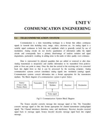
  • 1. UNIT V COMMUNICATION ENGINEERING 5.1 TELECOMMUNICATION SYSTEM Communication is a data transmitting technique in a format that utilizes continuous signals to transmit data including voice, image, video, electrons etc. An analog signal is a variable signal continuous in both time and amplitude which is generally carried by use of modulation. Analog circuits do not involve quantization of information unlike the digital circuits and consequently have a primary disadvantage of random variation and signal degradation, particularly resulting in adding noise to the audio or video quality over a distance. Data is represented by physical quantities that are added or removed to alter data. Analog transmission is inexpensive and enables information to be transmitted from point-to- point or from one point to many. Once the data has arrived at the receiving end, it is converted back into digital form so that it can be processed by the receiving computer. Analog communication systems convert (modulate) analog signals into modulated (analog) signals. Communication systems convert information into a format appropriate for the transmission medium. The Block diagram of a communication system is given below: Fig.5.1 Communication System Block Diagram The Source encoder converts message into message signal or bits. The Transmitter converts message signal or bits into format appropriate for channel transmission (analog/digital signal). The Channel introduces distortion, noise, and interference. Receiver decodes received signal back to message signal. Source decoder decodes message signal back into original message. Source (Voice, Code, Picture, Data) Transmitter Channel or Medium Destination Receiver Noise signal
  • 2. 5.2 Basic Electrical and Electronics Engineering Transmitter and Modulation Each system contains a transmitter. This consists of a source of electrical energy, producing alternating current of a desired frequency of oscillation. The transmitter contains a system to modulate (change) some property of the energy produced to impress a signal on it. This modulation might be as simple as turning the energy on and off, or altering more subtle properties such as amplitude, frequency, phase, or combinations of these properties. The transmitter sends the modulated electrical energy to a tuned resonant antenna; this structure converts the rapidly changing alternating current into an electromagnetic wave that can move through free space (sometimes with a particular polarization). Amplitude modulation of a carrier wave works by varying the strength of the transmitted signal in proportion to the information being sent. For example, changes in the signal strength can be used to reflect the sounds to be reproduced by a speaker, or to specify the light intensity of television pixels. It was the method used for the first audio radio transmissions, and remains in use today. "AM" is often used to refer to the medium wave broadcast band (see AM radio). Frequency modulation varies the frequency of the carrier. The instantaneous frequency of the carrier is directly proportional to the instantaneous value of the input signal. Digital data can be sent by shifting the carrier's frequency among a set of discrete values, a technique known as frequency-shift keying. FM is commonly used at VHF radio frequencies for high-fidelity broadcasts of music and speech (see FM broadcasting). Normal (analog) TV sound is also broadcast using FM. Angle modulation alters the instantaneous phase of the carrier wave to transmit a signal. It is another term for Phase modulation. Receiver and Demodulation The electromagnetic wave is intercepted by a tuned receiving antenna; this structure captures some of the energy of the wave and returns it to the form of oscillating electrical currents. At the receiver, these currents are demodulated, which is conversion to a usable signal form by a detector sub-system. The receiver is "tuned" to respond preferentially to the desired signals, and reject undesired signals.
  • 3. Communication Engineering 5.3 Early radio systems relied entirely on the energy collected by an antenna to produce signals for the operator. Radio became more useful after the invention of electronic devices such as the vacuum tube and later the transistor, which made it possible to amplify weak signals. Today radio systems are used for applications like walkie-talkie, children's toys, to the control of space vehicles, as well as for broadcasting, and many other applications. A radio receiver receives its input from an antenna, uses electronic filters to separate a wanted radio signal from all other signals, amplifies it to a level suitable for further processing, and finally converts through demodulation and decoding the signal into a form usable for the consumer, such as sound, pictures, digital data, measurement values, navigational positions, etc. Types of Communication Based on the nature of communication channel, the process of communication may be broadly classified into two types. 1. Wire-line communication system 2. Wireless communication system In wire line communication, we make use of a physical cable such as a wire or coaxial cable for carrying on signal. Such mode of communication is normally preferred for a short distance communication. Example for wire-line communication Cable network for entertainment / information broadcasting through satellite in a regional area. Telephone communication. Wireless communication system: In wireless communication system, free space or air is used as medium to carry the message from one place to other. Long distance communication is possible with wireless communication. Example Radio communication, TV reception.
  • 4. 5.4 Basic Electrical and Electronics Engineering Block Diagram of a Wireless Communication System: Fig.5.2 Block diagram of a wireless communication system Transmitter Transmitter is the first component in this block diagram. Using this system we can generate the messages which is to be sent through this system. Encoder Encoder is the second element in the communication system. It performs the encoding of the given data, which means that this system converts the messages in the form of symbols for transmission purpose. In this system, a sequence of characters are created in a special format for an effective transmission. This encoding system is used for security purpose. Noisy Channel This is the third block in the block diagram of communication system. Noisy channel is nothing but the medium through which the message is transmitted. Messages are conveyed through this channel. Different channels have different strengths and weaknesses. Each channel has its own frequency and different applications have different operating frequencies. Decoder Decoder is used to decode the encoded message and retrieve the actual message. Decoding must be done correctly. If this part is not performed well then the message which is
  • 5. Communication Engineering 5.5 received might not be correct This encoding and decoding will be very help full in military and mobile communications. Receiver This is the final block in block diagram of communication system. This can be said as the target to which the information need to be delivered. 5.2 TYPES OF SIGNALS The signals are generally classified into two types 1. Digital signal 2. Analog signal Fig 5.3 Digital + Analog Signal 1. Digital signals Basically, code 1 is transmitted when applying a specific voltage and code 0 is transmitted in the case of 0V. A system of transmitting digital signals is called baseband system. 2. Analog signals Signals 0 and 1 are transmitted as electric waves. A system of transmitting analog signals is called broadband system. 5.3 MODULATION In electronics and telecommunications, modulation is the process of varying one or more properties of a periodic waveform, called the carrier signal, with a modulating signal which typically contains information to be transmitted.
  • 6. 5.6 Basic Electrical and Electronics Engineering In telecommunications, modulation is the process of conveying a message signal, for example a digital bit stream or an analog audio signal, inside another signal that can be physically transmitted. Modulation of a sine waveform is used to transform a baseband message signal into a passband signal. A device that performs modulation is known as a modulator and a device that performs the inverse operation of modulation is known as a demodulator (sometimes detector or demod). A device that can do both operations is a modem (from "modulator–demodulator"). Modulating Signal The message signal / low frequency signal which is to be transmitted from one place to other is called as modulating signal. Carrier Signal The high frequency signal used for the purpose of modulation is called as carrier signal. Fig 5.4 a) Modulating signal (low frequency) b) Carrier signal (High frequency) Classification of Modulation Modulation can be broadly classified into two types based on the nature of carrier signal. 1. Sinusoidal Modulation 2. Pulse Modulation Sinusoidal Modulation Information can be used to modulate a high frequency carrier in three principle ways: by varying the carrier amplitude, frequency or phase. The simplest and most bandwidth efficient of these methods is amplitude modulation.
  • 7. Communication Engineering 5.7 Pulse Modulation In pulse modulation, the carrier signal used is a pulse signal. The amplitude, position or width of the pulse is varied accordance to the instantaneous amplitude variations of the modulating signal for the purpose of modulation. Sinusoidal Modulation Techniques Sinusoidal modulation may be classified into two types. 1. Amplitude Modulation 2. Frequency Modulation 5.3.1 Amplitude Modulation Time domain An AM signal is made up of a carrier (with constant frequency) in which its amplitude is changed (modulated) with respect to the signal (modulating signal) we wish to transmit (voice, music, data, binary). In the example below the carrier (a high frequency sine wave) is being modulated by a lower frequency sine wave. The modulating signal causes the carriers amplitude to change with time. This resulting shape of the carrier is called the envelope. Note the envelope has the shape of a sine wave. Fig 5.5.AM signal
  • 8. 5.8 Basic Electrical and Electronics Engineering Fig.5.6 Modulating signal (sine wave) and modulated carrier Fig. 5.7 Modulating signal (Audio) and modulated carrier Derivation A carrier is described by v = Vc Sin ( c t + )
  • 9. Communication Engineering 5.9 To amplitude modulate the carrier its amplitude is changed in accordance with the level of the audio signal, which is described by v = Vm Sin (m t) The amplitude of the carrier varies sinusoidally about a mean of Vc. When the carrier is modulated its amplitude is varied with the instantaneous value of the modulating signal. The amplitude of the variation of the carrier amplitude is Vm and the angular frequency of the rate at which the amplitude varies is m. The amplitude of the carrier is then: Carrier amplitude = Vc + Vm Sin (m t) and the instantaneous value (value at any instant in time) is v = {Vc + Vm Sin (m t)} * Sin (c t) (1) = Vc Sin (c t) + Vm Sin (m t) * Sin (c t) Using Sin A * Sin B = ½ Cos (A - B) - ½ Cos (A + B) this becomes v = Vc Sin ( c t ) + ½ Vm Cos ( (c - m) t ) - ½ Vm Cos ((c + m)t (2) This is a signal made up of 3 signal components  carrier at c (rad/s) Frequency is fc = c/2 Hz  upper side frequency c + m (rad/s) Frequency is (c + m)/2 = fm + fc Hz  lower side frequency c - m (rad/s) Frequency is (c - m)/2 = fm - fc Hz The bandwidth (the difference between the highest and the lowest frequency) is BW = (c + m ) - (c - m) = 2 * m Rad/s ( = m/ Hz) The spectrum of these signals is shown. This is described as the signal in the frequency domain, as opposed to the signal in the time domain. In this case the audio signal is made up of a single frequency. In this example the angular frequencies (expressed in Radians/sec, or kRad/sec, or Mrad/sec) are show. In most cases however the frequency is shown (expressed in Hz, or kHz, or MHz).
  • 10. 5.10 Basic Electrical and Electronics Engineering If the audio signal is made up of a range of frequencies from f1 to f2 (as is normally the case) rather than a single frequency the output signal will be a band of frequencies, contained in.  the upper side band (USB), inverted and  the lower side band (LSB), erect. A broadcast AM station in the Medium Wave band is usually allocated a frequency slot 9 kHz wide. This means that the carriers of stations in this band are spaced 9 kHz apart. The maximum amplitude in an AM signal is Vc + Vm .The minimum amplitude is Vc - Vm. Fig. 5.8 Modulation Index (or Modulation Factor or Depth of Modulation) This is defined as m = Vm Vc In AM, this quantity, also called modulation depth, indicates by how much the modulated signal varies around its 'original' level. For AM, it relates to the variations in the carrier amplitude. Amplitude (V) Angular Frequency c c + m c - m Lower side frequency Carrier Upper side frequency Bandwidth = 2 * m
  • 11. Communication Engineering 5.11 Using this Eqn. can be re-written as v = Vc Sin ( c t ) + ½ (Vm Cos ( (c - m) t ) - Vm Cos ((c + m)t) ) * Vc /Vc v = Vc { Sin ( c t ) + ½ m [ Cos ( (c - m) t ) + Cos ((c + m)t) ] } Power in an AM waveform Assume that the AM signal is dissipated in a load of R . The total power dissipated will be the sum of the powers in all of the components of the signal. The power in the carrier will be Pc = Vc 2 R Watts The power in each of the frequencies is Ps = (mVc/2)2 R = m2 4 Vc 2 R = m2 4 Pc The total power is Pt = Pc + Ps + Ps = Pc + 2 Ps = Pc ( 1 + 2 m2 4 ) = Pc ( 1 + m2 2 ) Watts The fraction of the power in the carrier is Pc Pt = 1 1 + m2 2 The maximum value for m is 1.0. This means that at most only 1/3 of the power in the signal will be contained in the sidebands. All of the audio information is contained in either one of the sidebands, so that, in effect, only one sixth of the power (16.7%) is used to carry information. The remainder of the signal can in some respects be considered to be redundant! Peak Instantaneous Power The maximum signal voltage is Vc + Vm = Vc (1 + m) so that the maximum instantaneous output power is Vc 2 R (1 + m)2 = Pc (1 + m)2 .
  • 12. 5.12 Basic Electrical and Electronics Engineering If the modulation index is 1.0 the maximum output power will be 4 Pc. The transmitter must be designed to carry this level of output power. Frequency Modulation In telecommunications and signal processing, frequency modulation (FM) is the encoding of information in a carrier wave by varying the instantaneous frequency of the wave. (Compare with amplitude modulation, in which the amplitude of the carrier wave varies, while the frequency remains constant.) In analog signal applications, the difference between the instantaneous and the base frequency of the carrier is directly proportional to the instantaneous value of the input-signal amplitude. If the information to be transmitted (i.e., the baseband signal) is m x (t) and the sinusoidal carrier is c c c x (t) A cos(2 f t)   , where fc is the carrier's base frequency, and Ac is the carrier's amplitude, the modulator combines the carrier with the baseband data signal to get the transmitted signal:   t c 0 y(t) A cos 2 f( )d          t c c m 0 A cos 2 f f x ( ) d          t c c m 0 A cos 2 f t 2 f x ( )d         In this equation, f ( )  is the instantaneous frequency of the oscillator and f is the frequency deviation, which represents the maximum shift away from fc in one direction, assuming xm(t) is limited to the range ±1. Modulation index As in other modulation systems, this quantity indicates by how much the modulated variable varies around its unmodulated level. It relates to variations in the carrier frequency: m m m f | x (t) | f h f f    
  • 13. Communication Engineering 5.13 where is the highest frequency component present in the modulating signal xm(t), and f  is the peak frequency-deviation—i.e. the maximum deviation of the instantaneous frequency from the carrier frequency. If h << 1, the modulation is called narrowband FM, and its bandwidth is approximately m 2f . If h >> 1 , the modulation is called wideband FM and its bandwidth is approximately 2f . Fig 5.9
  • 14. 5.14 Basic Electrical and Electronics Engineering Bandwidth Ideally the bandwith of FM signal is infinite but however in practical cases, as the number of side bands are limite to a finite number, the bandwith is an integral multiple of modulating signal frequency. Spectrum of FM Fig 5.10 5.3.2 Pulse Modulation In pulse modulation, a pulse is used as the carrier and amplitude, position or width of the pulse is varied in accordance to the message signal amplitude. Accordingly pulse modulation may be classified into following types. 1. Pulse Amplitude Modulation 2. Pulse Position Modulation 3. Pulse Width Modulation
  • 15. Communication Engineering 5.15 Fig. 5.11 Pulse Amplitude Modulation Pulse-amplitude modulation (PAM), is a form of signal modulation where the message information is encoded in the amplitude of a series of signal pulses. It is an analog pulse modulation scheme in which the amplitudes of a train of carrier pulses are varied according to the sample value of the message signal. Pulse Position Modulation Pulse-position modulation (PPM) is a form of signal modulation in which M message bits are encoded by transmitting a single pulse in one of 2M possible time-shifts. This is repeated every T seconds, such that the transmitted bit rate is M/T bits per second. It is primarily useful for optical communications systems, where there tends to be little or no multipath interference.
  • 16. 5.16 Basic Electrical and Electronics Engineering Pulse Width Modulation Pulse - width modulation (PWM), or pulse - duration modulation (PDM), is a modulation technique that conforms the width of the pulse, formally the pulse duration, based on modulator signal information. Although this modulation technique can be used to encode information for transmission, its main use is to allow the control of the power supplied to electrical devices, especially to inertial loads such as motors. In addition, PWM is one of the two principal algorithms used in photovoltaic solar battery chargers, the other being MPPT. 5.3.3 Digital Modulation In digital modulation, an analog carrier signal is modulated by a discrete signal. Digital modulation methods can be considered as digital-to-analog conversion, and the corresponding demodulation or detection as analog-to-digital conversion. The changes in the carrier signal are chosen from a finite number of M alternative symbols (the modulation alphabet). Digital Data Digital data is nothing but the representation of information in the form of 0’s and 1’s Why Digital Modulation? The move to digital modulation provides more information capacity, compatibility with digital data services, higher data security, better quality communications, and quicker system availability. Developers of communications systems face these constraints:  available bandwidth  permissible power  inherent noise level of the system The RF spectrum must be shared, yet every day there are more users for that spectrum as demand for communications services increases. Digital modulation schemes have greater capacity to convey large amounts of information than analog modulation schemes. PCM (Pulse Code Modulation) Pulse-code modulation (PCM) is a method used to digitally represent sampled analog signals. It is the standard form of digital audio in computers, Compact Discs, digital telephony and other digital audio applications. In a PCM stream, the amplitude of the analog
  • 17. Communication Engineering 5.17 signal is sampled regularly at uniform intervals, and each sample is quantized to the nearest value within a range of digital steps. Quantization Noise occurs in PCM. PCM streams have two basic properties that determine their fidelity to the original analog signal: the sampling rate, the number of times per second that samples are taken; and the bit depth, which determines the number of possible digital values that each sample can take. PCM can be either return-to-zero (RZ) or non-return-to-zero (NRZ). For a NRZ system to be synchronized using in-band information there must not be long sequences of identical symbols, such as ones or zeroes. For binary PCM systems, the density of 1-symbols is called ones-density. Unipolar and polar signaling Digital Transmission Data transmission, digital transmission, or digital communications is the physical transfer of data (a digital bit stream) over a point–to–point or point–to–multipoint communication channel. Examples of such channels are copper wires, optical fibres, wireless communication channels, and storage media. The data are represented as an electromagnetic signal, such as an electrical voltage, radio wave, microwave, or infrared signal.
  • 18. 5.18 Basic Electrical and Electronics Engineering There are many different modulation techniques that can be utilised in a modem.These techniques are: Amplitude shift key modulation (ASK),Frequency shift key modulation (FSK),Phase shift key modulation (PSK), etc… Fig. General block diagram for digital transmission ASK Amplitude-shift keying (ASK) is a form of amplitude modulation that represents digital data as variations in the amplitude of a carrier wave. Any digital modulation scheme uses a finite number of distinct signals to represent digital data. ASK uses a finite number of amplitudes, each assigned a unique pattern of binary digits. Usually, each amplitude encodes an equal number of bits. Each pattern of bits forms the symbol that is represented by the particular amplitude. The demodulator, which is designed specifically for the symbol-set used by the modulator, determines the amplitude of the received signal and maps it back to the symbol it represents, thus recovering the original data. Frequency and phase of the carrier are kept constant.
  • 19. Communication Engineering 5.19 Fig. ASK, PSK, FSK modulated waveforms PSK Phase-shift keying (PSK) is a digital modulation scheme that conveys data by changing, or modulating, the phase of a reference signal (the carrier wave). Any digital modulation scheme uses a finite number of distinct signals to represent digital data. PSK uses a finite number of phases, each assigned a unique pattern of binary digits. Usually, each phase encodes an equal number of bits. Each pattern of bits forms the symbol that is represented by the particular phase. The demodulator, which is designed specifically for the symbol-set used by the modulator, determines the phase of the received signal and maps it back to the symbol it represents, thus recovering the original data. This requires the receiver to be able to compare the phase of the received signal to a reference signal such a system is termed coherent (and referred to as CPSK). FSK Frequency-shift keying (FSK) is a frequency modulation scheme in which digital information is transmitted through discrete frequency changes of a carrier wave. The simplest FSK is binary FSK (BFSK). BFSK uses a pair of discrete frequencies to transmit binary (0s and 1s) information. With this scheme, the “1” is called the mark frequency and the “0” is
  • 20. 5.20 Basic Electrical and Electronics Engineering called the space frequency. The time domain of an FSK modulated carrier is illustrated in the figures to the right. 5.4 RADIO COMMUNICATION Radio is the wireless transmission of signals through free space by electromagnetic radiation of a frequency significantly below that of visible light, in the radio frequency range, from about 30 kHz to 300 GHz.[1] These waves are called radio waves. Electromagnetic radiation travels by means of oscillating electromagnetic fields that pass through the air and the vacuum of space. Information, such as sound, is carried by systematically changing (modulating) some property of the radiated waves, such as their amplitude, frequency, phase, or pulse width. When radio waves strike an electrical conductor, the oscillating fields induce an alternating current in the conductor. The information in the waves can be extracted and transformed back into its original form. Propagation of Radio Waves Radio propagation is also affected by several other factors determined by its path from point to point. This path can be a direct line of sight path or an over-the-horizon path aided by refraction in the ionosphere, which is a region between approximately 60 and 600 km.[3] Factors influencing ionospheric radio signal propagation can include sporadic-E, spread-F, solar flares, geomagnetic storms, ionospheric layer tilts, and solar proton events. Free space propagation In free space, all electromagnetic waves (radio, light, X-rays, etc.) obey the inverse- square law which states that the power density of an electromagnetic wave is proportional to the inverse of the square of the distance from a point source or: P 2 1 r   Doubling the distance from a transmitter means that the power density of the radiated wave at that new location is reduced to one-quarter of its previous value. The power density per surface unit is proportional to the product of the electric and magnetic field strengths. Thus, doubling the propagation path distance from the transmitter reduces each of their received field strengths over a free-space path by one-half.
  • 21. Communication Engineering 5.21 Modes Surface modes (groundwave) Lower frequencies (between 30 and 3,000 kHz) have the property of following the curvature of the earth via groundwave propagation in the majority of occurrences. In this mode the radio wave propagates by interacting with the semi-conductive surface of the earth. The wave "clings" to the surface and thus follows the curvature of the earth. Verticalpolarization is used to alleviate short circuiting the electric field through the conductivity of the ground. Since the ground is not a perfect electrical conductor, ground waves are attenuated rapidly as they follow the earth’s surface. Attenuation is proportional to the frequency making this mode mainly useful for LF and VLF frequencies (see also Earth-ionosphere waveguide). Direct modes (line-of-sight) Line-of-sight is the direct propagation of radio waves between antennas that are visible to each other. This is probably the most common of the radio propagation modes at VHF and higher frequencies. Because radio signals can travel through many non-metallic objects, radio can be picked up through walls. This is still line-of-sight propagation. Examples would include propagation between a satellite and a ground antenna or reception of television signals from a local TV transmitter. Ground plane reflection effects are an important factor in VHF line of sight propagation. The interference between the direct beam line-of-sight and the ground reflected beam often leads to an effective inverse-fourth-power i.e. (1/distance)^4 law for ground-plane limited radiation. [Need reference to inverse-fourth-power law + ground plane. Drawings may clarify] Ionospheric modes (skywave) Skywave propagation, also referred to as skip, is any of the modes that rely on refraction of radio waves in the ionosphere, which is made up of one or more ionized layers in the upper atmosphere. F2-layer is the most important ionospheric layer for long-distance, multiple-hop HF propagation, though F1, E, and D-layers also play significant roles. The D-layer, when present during sunlight periods, causes significant amount of signal loss, as does the E-layer whose maximum usable frequency can rise to 4 MHz and above and thus block higher frequency signals from reaching the F2-layer.
  • 22. 5.22 Basic Electrical and Electronics Engineering Band Frequency Wavelength Applications ELF Extremely Low Frequency 3 – 300 Hz 1000 – 100,000 km VLF Very Low Frequency 3 – 30 kHz 100–10 km Long distance communication LF Low Frequency 30 – 300 kHz 10–1 km Navigation, time standards MF Medium Frequency 300–3000 kHz 1000–100 m Marine/aircraft navigation HF High Frequency (Short Wave) 3–30 MHz 100–10 m Mobile radio VHF Very High Frequency 30–300MHz 10–1 m Land mobile, FM broadcasting, Television, Radar UHF Ultra High Frequency 300–3000 MHz 100 – 10 cm Cell phones, Television, WLAN SHF Super High Frequency 3–30 GHz 10 – 1 cm Satellite, Radar navigation EHF Extremely High Frequency 30–300 GHz 10 – 1 mm Satellite, Radar navigation Radio Transmitters In electronics and telecommunications a transmitter or radio transmitter is an electronic device which, with the aid of an antenna, produces radio waves. The transmitter itself generates a radio frequency alternating current, which is applied to the antenna. When excited by this alternating current, the antenna radiates radio waves. In addition to their use in broadcasting, transmitters are necessary component parts of many electronic devices that communicate by radio, such as cell phones, wireless computer networks, Bluetooth enabled devices, garage door openers, two-way radios in aircraft, ships, and spacecraft, radar sets, and navigational beacons. The term transmitter is usually limited to equipment that generates radio waves for communication purposes; or radiolocation, such as radar and navigational transmitters.
  • 23. Communication Engineering 5.23 Generators of radio waves for heating or industrial purposes, such as microwave ovens or diathermy equipment, are not usually called transmitters even though they often have similar circuits. The term is popularly used more specifically to refer to a broadcast transmitter, a transmitter used in broadcasting, as in FM radio transmitter or AM video transmitter. This usage usually includes both the transmitter proper, the antenna, and often the building it is housed in. An unrelated use of the term is in industrial process control, where a "transmitter" is a telemetry device which converts measurements from a sensor into a signal, and sends it, usually via wires, to be received by some display or control device located a distance away. AM Transmitter  Amplitude modulation technique is used in AM transmitters, here the amplitude of carrier is varied in proportion with the amplitude of the modulating signal, keeping its frequency and phase constant.  Used in radio & TV broadcasting.  In AM Transmitter, AM signal is transmitted by a transmitter. The information is contained in its amplitude variation.  It has classified as two types  Low Level modulation transmitters.  High Level modulation transmitters.
  • 24. 5.24 Basic Electrical and Electronics Engineering Low Level modulation transmitters  The generation of AM wave takes place at a low power level.  The generated AM signal is then amplified using a chain of linear amplifier ( A, AB or B).  The RF oscillator produces the carrier signal. The RF oscillator is stabilized in order to maintain the frequency deviation within the prescribed limit. The carrier frequency is equal to the transmitter frequency.  Usually the transmitter operates on assigned frequencies or channels. Crystal provides the best way to obtain the described frequency with good stability.  We cannot use the LC oscillator because they have low frequency stability.  The carrier signal from the crystal oscillator is applied to the modulator with a modulating signal. At the output of the modulator we get the AM wave.  The modulating signal is obtained from a source such as a microphone and applied to a buffer processing unit.  The buffer is a class A amplifier which isolates the AF source from the rest of high power circuit and amplifies it to an adequate level.  The amplified modulating signal is applied to the modulator along with the carrier. At the output of the modulator we get the AM wave.  The AM signal is then amplified using a chain of linear amplifier to raise the power level.  The linear amplifier can be class A, AB or B type amplifiers. The linear amplifier are used in order to avoid the wave form distortion in AM wave.  The amplitude modulated signal is then transmitted using transmitted antenna.  The transistorized modulator circuits can be used for low level modulator due to the low power which is to be handled.  The low level transmitter does not require a large AF modulator power so its design is simplified.
  • 25. Communication Engineering 5.25  Overall efficiency is much lower compared to high level modulation . This reduce to the use of less efficient linear amplifiers. Fig. Low level AM transmitter block diagram  The RF oscillator produces the carrier signal. The RF oscillator is stabilized in order to maintain the frequency deviation within the prescribed limit. The carrier frequency is equal to the transmitter frequency.  Usually the transmitter operates on assigned frequencies or channels. Crystal provides the best way to obtain the described frequency with good stability.  We cannot use the LC oscillator because they have low frequency stability.  The carrier signal from the crystal oscillator is applied to the modulator with a modulating signal. At the output of the modulator we get the AM wave.  The modulating signal is obtained from a source such as a microphone and applied to a buffer processing unit.  The buffer is a class A amplifier which isolates the AF source from the rest of high power circuit and amplifies it to an adequate level.  The amplified modulating signal is applied to the modulator along with the carrier. At the output of the modulator we get the AM wave.  The AM signal is then amplified using a chain of linear amplifier to raise the power level.  The linear amplifier can be class A, AB or B type amplifiers. The linear amplifier are used in order to avoid the wave form distortion in AM wave.  The amplitude modulated signal is then transmitted using transmitted antenna.
  • 26. 5.26 Basic Electrical and Electronics Engineering  The transistorized modulator circuits can be used for low level modulator due to the low power which is to be handled.  The low level transmitter does not require a large AF modulator power so its design is simplified. High level Transmitter  Highly efficient class C amplifier are used in high level modulation.  Efficiency is more than low level modulation. Fig. High level AM transmitter block diagram  Many of the AM transmitters use the high level modulation technique.  The crystal oscillator produces the required carrier signal. The class A amplifier following the oscillator acts as a buffer which isolates the oscillator from the high power circuit.  The output of this class A amplifier is applied to a class C power amplifier. It raises the power level of the carrier to an intermediately high value.  The AF modulating signal is applied to the audio processing unit which processes this signal as discussed in the previous section. FM TRANSMITTERS FM modes Angle modulation is the proper term for modulation by changing the instantaneous frequency or phase of the carrier signal. True FM and phase modulation are the most commonly employed forms of analogue angle modulation.
  • 27. Communication Engineering 5.27 It broadly classified as two types 1. Direct FM 2. Indirect FM Direct FM Direct FM (true Frequency modulation) is where the frequency of an oscillator is altered to impose the modulation upon the carrier wave. This can be done by using a voltage- controlled capacitor (Varicap diode) in a crystal-controlled oscillator or frequency synthesiser. The frequency of the oscillator is then multiplied up using a frequency multiplier stage, or is translated upwards using a mixing stage, to the output frequency of the transmitter. The amount of modulation is referred to as the deviation, being the amount that the frequency of the carrier instantaneously deviates from the centre carrier frequency. Fig. Direct fm transmitter block diagram Indirect FM Indirect FM employs a varicap diode to impose a phase shift (which is voltage- controlled) in a tuned circuit that is fed with a plain carrier. This is termed phase modulation. In some indirect FM solid state circuits, an RF drive is applied to the base of a transistor. The tank circuit (LC), connected to the collector via a capacitor, contains a pair of varicap diodes. As the voltage applied to the varicaps is changed, the phase shift of the output will change. Transmitting antenna
  • 28. 5.28 Basic Electrical and Electronics Engineering Phase modulation is mathematically equivalent to direct Frequency modulation with a 6dB/octave high-pass filter applied to the modulating signal. This high-pass effect can be exploited or compensated for using suitable frequency-shaping circuitry in the audio stages ahead of the modulator. For example, many FM systems will employ pre-emphasis and de- emphasis for noise reduction, in which case the high-pass equivalency of phase modulation automatically provides for the pre-emphasis. Phase modulators are typically only capable of relatively small amounts of deviation while remaining linear, but any frequency multiplier stages also multiply the deviation in proportion. The part of the Armstrong FM transmitter (Armstrong phase modulator) which is expressed in dotted lines describes the principle of operation of an Armstrong phase modulator. It should be noted, first that the output signal from the carrier oscillator is supplied to circuits that perform the task of modulating the carrier signal. The oscillator does not change frequency, as is the case of direct FM. These points out the major advantage of phase modulation (PM), or indirect FM, over direct FM. That is the phase modulator is crystal controlled for frequency. Fig. Indirect fm transmitter block diagram The balanced modulator is an amplitude modulator used to form an envelope of double side-bands and to suppress the carrier signal (DSSC). This requires two input signals, the carrier signal and the modulating message signal. The output of the modulator is connected to the adder circuit; here the 90° phase-delayed carriers signal will be added back to replace the suppressed carrier. The act of delaying the carrier phase by 90° does not change the carrier frequency or its wave-shape. This signal identified as the 90° carrier signal. Crysta l Tx antenna
  • 29. Communication Engineering 5.29 Radio Receivers In radio communications, a radio receiver is an electronic device that receives radio waves and converts the information carried by them to a usable form. It is used with an antenna. The antenna intercepts radio waves (electromagnetic waves) and converts them to tiny alternating currents which are applied to the receiver, and the receiver extracts the desired information. The receiver uses electronic filters to separate the desired radio frequency signal from all the other signals picked up by the antenna, an electronic amplifier to increase the power of the signal for further processing, and finally recovers the desired information through demodulation. The information produced by the receiver may be in the form of sound (an audio signal), images (a video signal) or data (adigital signal).[1] A radio receiver may be a separate piece of electronic equipment, or an electronic circuit within another device. Devices that contain radio receivers include television sets, radar equipment, two-way radios, cell phones,wireless computer networks, GPS navigation devices, satellite dishes, radio telescopes, bluetooth enabled devices,garage door openers, and baby monitors. In consumer electronics, the terms radio and radio receiver are often used specifically for receivers designed to reproduce the audio (sound) signals transmitted by radio broadcasting stations – historically the first mass-marketcommercial radio application. AM and FM Receivers Two methods of modulation used in radio broadcasts are amplitude modulation(AM) and frequency modulation(FM). A receiver meant to receive amplitude modulated wave is known as an AM receiver and a receiver meant to receive frequency modulated wave is known as an FM receiver. Types of Receiver The principle of operation following receivers are a) TRF Receiver b) Super heterodyne AM receiver c) FM receiver
  • 30. 5.30 Basic Electrical and Electronics Engineering TRF Receiver A tuned radio frequency receiver (TRF receiver) is a radio receiver that is usually composed of several tuned radio frequency amplifiers followed by circuits to detect and amplify the audio signal. Prevalent in the early 20th century, it can be difficult to operate because each stage must be individually tuned to the station's frequency. Fig. Block diagram of TRF receiver Disadvantages of TRF Term an (1943, p. 658) characterizes the TRF's disadvantages as "poor selectivity and low sensitivity in proportion to the number of tubes employed. They are accordingly practically obsolete." Selectivity requires narrow bandwidth, and narrow bandwidth at a high radio frequency implies high Q or many filter sections. In contrast a super heterodyne receiver can translate the incoming high radio frequency to a lower intermediate frequency where selectivity is easier to achieve. An additional problem for the TRF receiver is tuning different frequencies. All the tuned circuits need to track to keep the narrow bandwidth tuning. Keeping several tuned circuits aligned is difficult. A super heterodyne receiver only needs to track the RF and LO stages; the onerous selectivity requirements are confined to the IF amplifier which is fixed-tuned. Receiving antenna Loud speaker
  • 31. Communication Engineering 5.31 Although a TRF receiver can not be engineered for a high degree of selectivity relative to its carrier frequency, there is no reason it cannot reach the same level of sensitivity as other designs. The 1930s era BC-AN-229/429 military receiver was a six-valve design covering 201 to 398 kHz and 2.5 to 7.7 MHz (requiring several sets of plug-in coils to cover those ranges). This equipment probably exemplifies the limit of T.R.F. performance. Although the receiver bandwidth does vary, as noted above, the sensitivity of the set was around 8 microvolts for 10 milliwatts of audio output, comparable to that of the famous AN/ARC-5 superhet receiver that superseded it. Super heterodyne AM receiver In superheterodyne radio receivers, the incoming radio signals arc intercepted by the antenna arid converted into the corresponding currents and voltages. In the receiver, the incoming signal frequency is mixed with a locally generated frequency. The output of the mixer consists of the sum and difference of the two frequencies. The mixing of the two frequencies is termed heterodyning. Out of the two resultant components of the mixer, the sum component is rejected and the difference component is selected. The value of the difference frequency component varies with the incoming frequencies, if the frequency of the local oscillator is kept constant. It is possible to keep the frequency of the difference components constant by varying the frequency of the local oscillator according to the incoming signal frequency. In this case, the process is called Superheterodyne and the receiver is known as a superheterodyne radio receiver. Fig. Block diagram of a super heterodyne and AM receiver Loud speaker
  • 32. 5.32 Basic Electrical and Electronics Engineering In Figure the receiving antenna intercepts the radio signals and feeds the RF amplifier, The RF amplifier selects the desired signal frequency and amplifies its voltage, The RF' amplifier is a small-signal voltage amplifier that operates in the RF range. This amplifier is tuned to the desired signal frequency by using capacitive tuning. After suitable amplification of the RF signal it is fed to the mixer. The mixer takes another input from a local oscillator, which generates a frequency according to the frequency of the selected signal so that the difference equals. a predetermined value. The mixer consists of a non-linear device, such as a transistor. Due to the non-linearity, the mixer output consists of a number of frequency components. It provides sum and difference frequency components along with their higher harmonics. A tuned circuit at the output of the mixer selects only the difference component while rejecting all other components. The difference component is called the intermediate frequency or IF the value of IF frequency is always constant and is equal to 455 KHz. For a constant IF frequency for all incoming signals, the frequency of the local oscillator is adjusted using capacitive tuning. The incoming signal is also selected using capacitive tuning. The two capacitors used to select the incoming signal and the oscillator frequency is ganged together so that the tuning of both the RF amplifier and the local oscillator circuits is done simultaneously. This arrangement ensures that the local oscillator has the correct frequency to generate constant IF frequencies. The mixer stage is also tuned to IF frequency using capacitive tuning. The tuning capacitor is also ganged with the RF amplifier and the local oscillator. Thus all the three stages are tuned at the same time to the required frequency through the ganged Capacitor, which consists of the three tuning capacitors. The IF signal is fed to an IF amplifier with two amplifier stages. This provides enough signal amplification so that the signal is properly detected. The amplified IF signal is fed to the lineardiode detector, which demodulates the received AM signal. The output of the detector stage is the original modulating signal. This signal is given to the audio driver stage, which amplifies its voltage to drive the power amplifier, which is the last stage of the receiver. The power of the modulating signal and finally is passed to the power amplifier amplifies the speaker. The speaker converts the audio currents into sound energy.
  • 33. Communication Engineering 5.33 FM Receiver The block diagram of an FM receiver is illustrated in Figure (a). The RF amplifier amplifies the received signal intercepted by the antenna. The amplified signal is then applied to the mixer stage. The second input of the mixer comes from the local oscillator. The two input frequencies of the mixer generate an IF signal of 10.7 MHz. This signal is then amplified by the IF amplifier. Figure (a) shows the block diagram of an FM receiver. The output of the IF amplifier is applied to the limiter circuit. The limiter removes the noise in the received signal and gives a constant amplitude signal. This circuit is required when a phase discriminator is used to demodulate an FM signal. Fig. Block diagram of FM receiver The output of the limiter is now applied to the FM discriminator, which recovers the modulating signal. However, this signal is still not the original modulating signal. Before applying it to the audio amplifier stages, it is de-emphasized. De-emphasizing attenuates the higher frequencies to bring them back to their original amplitudes as these are boosted or emphasized before transmission. The output of the de-emphasized stage is the audio signal, which is then applied to the audio stages and finally to the speaker. It should be noted that a limiter circuit is required with the FM discriminators. If the demodulator stage uses a ratio detector instead of the discriminator, then a limiter is not required. This is because the ratio detector limits the amplitude of the received signal. In Figure (a) a dotted block that covers the limiter and the discriminator is marked as the ratio detector.
  • 34. 5.34 Basic Electrical and Electronics Engineering In FM receivers, generally, AGC is not required because the amplitude of the carrier is kept constant by the limiter circuit. Therefore, the input to the audio stages controls amplitudes and there are no erratic changes the volume level. However, AGC may be provided using an AGC detector. This generates a dc voltage to control the gains of the RF and IF amplifier. RF Amplifier Using FET The RF amplifier in FM receivers uses FETs as the amplifying device. A bipolar junction transistor can also be used for the purpose, but an FET has certain advantages over BJT. These are explained below:  An FET follows the square law for its operation, the characteristics; curves of an FET have non-linear regions. Due to the non-linearity, higher harmonics of the signal frequency are generated in the output. The major advantage of an FET is that it generates only the second harmonic components of the signal. This is known as the square law. Harmonics higher than the second harmonic is nearly absent in the output of an FET amplifier. The higher harmonics produce harmonic distortions and arc undesirable. In FETs, as only the second harmonics are present; it is easy to filter these out by using the tuned circuits. BJTs also generate higher harmonics, but they do not follow the square law. Therefore, they provide more harmonic distortion than FETs. Thus, FETs are always preferred in the RF amplifier of an FM receiver.  In BJT amplifiers, cross-modulation occurs if a strong signal of an adjacent channel gets through the tuned circuits in the presence of a weak desired signal. The adjacent channel will generate higher harmonics, which may come within the pass-band of the desired signal. This will produce noise and distortions at the output. On the other hand, The effect of cross-modulation is minimized in FET amplifiers, as the unwanted adjacent channel will also produce only its second harmonic components, which may not fall into the pass-band of the desired channel and thus are easily filtered out.  The input impedance of an FET becomes small due to the small input capacitive reactance of FET at very high FM frequencies. This makes it easy to match the small impedance of the antenna, typically 100 ohms, with the small input impedance of PET. This is not possible with BJTs.
  • 35. Communication Engineering 5.35 5.5 TELEVISION COMMUNICATION SYSTEM Introduction The aim of a television system is to extend the sense of sight beyond its natural limits and to transmit sound associated with the scene. The picture signal is generated by a TV camera and sound signal by a microphone. In the 625 lines CCIR monochrome and PAL-B colour TV. A system adopted by India, the picture signal is amplitude modulated and sound signal frequency modulated before transmission. The two carrier frequencies are suitably spaced and their modulation products radiated through a common antenna. As in radio communication, each television station is allotted different carrier frequencies to enable selection of desired station at the receiving end. The TV receiver has tuned circuits in its input section called 'tuner'. It selects desired channel signal out of the many picked up by the antenna. The selected RF band is' converted to a common fixed IF band for convenience of providing large amplification to it. The amplified IF signals are detected to obtain video (picture) and audio (sound) signals. The video signal after large amplification drives the picture tube to reconstruct the televised picture on the receiver screen. Similarly, the audio Signal is amplified and fed to the loudspeaker to produce sound output associated with the scene. PICTURE TRANSMISSION The picture information is optical in character and may be thought of as an assemblage of a large number of tiny areas representing picture details. These elementary areas into which picture details may be broken up are known as 'picture elements' or 'pixels', which when viewed together represent visual information of the scene. Thus, at any instant there are almost an infinite number of pieces of information that need to be picked up simultaneously for transmitting picture details. However, simultaneous pick-up is not practicable because it is not feasible to provide a separate signal path (channel) for the signal obtained from each picture element.
  • 36. 5.36 Basic Electrical and Electronics Engineering In practice, this problem is solved by a method known as 'scanning' where conversion of optical information to electrical form is carried out element by element, one at a time and in a sequential manner to cover the entire picture. Besides, scanning is done at a very fast rate and repeated a large number of times per second to create an illusion (impression at the eye) of simultaneous reception from all the elements, though using only one signal path. TELEVISION TRANSMITTER An oversimplified block diagram of a monochrome TV transmitter is shown in Fig. 1. The luminance signal from the camera is amplified and synchronizing pulses added before feeding it to the modulating amplifier. Synchronizing pulses are transmitted to keep the camera and picture tube beams in step. The allotted picture carrier frequency is generated by a crystal controlled oscillator. The continuous wave (CW) sine wave output is given large amplification before feed in to the power amplifier where its amplitude is made to vary (AM) in accordance with the modulating signal received from the modulating amplifier. The modulated output is combined (see Fig. 1.) with the frequency modulated (FM) sound signal in the combining network and then fed to the transmitting antenna for radiation. Fig. Elementary block diagram of a monochrome television transmitter. Microphone Audio signal Scanning and synchronizing circuits FM modulating amplifier Audio transmitter Crystal oscilllato r Power amplifier Transmitting Antenna Optical source Camera tube Video amplifier AM modulating amplifier Combining unit
  • 37. Communication Engineering 5.37 SOUND TRANSMISSION There is no difference in sound transmission between monochrome and colour TV systems. The microphone converts the sound associated with the picture being televised into proportionate electrical signal, which Is normally a voltage. This electrical output, regardless of the complexity of its waveform, is a single valued function of time and so needs a single channel for its transmission. The audio signal from the microphone after amplification is frequency modulated, employing the assigned carrier frequency. In FM, the amplitude of carrier signal is held constant, whereas its frequency is varied in accordance with amplitude variations of the modulating signal. As shown in Fig. Output of the sound FM transmitter Is finally combined with the AM picture transmitter output, through a combining network, and fed to a common antenna for radiation of energy in the form of electromagnetic waves. TELEVISION RECEIVER A simplified block diagram of a black and white TV receiver is shown in Fig. The receiving antenna intercepts radiated RF signals and the tuner selects desired. Fig. Simplified block diagram of a black and white TV receiver Receiver Antenna Loud speaker Picture tube Audio IF amplifier and demodulator Audio amplifier Vedio detector RF tuner and amplifier Vedio amplifier Scanning and synchronizing circuits
  • 38. 5.38 Basic Electrical and Electronics Engineering SCANNING The scene is scanned rapidly both in the horizontal and vertical directions simultaneously to provide sufficient number of complete pictures or frames per second to give the illusion of continuous motion. Instead of 24 as is the practice in commercial motion pictures, the frame repetition rate is 25 per second in most television systems. Horizontal Scanning Deflects the beam across the screen a continuous, uniform motion for the trace from left to right. At the peak of its rise, the sawtooth wave reverses direction and decreases rapidly to its Initial value. This fast reversal produces the retrace or flyback. The start of horizontal trace is at the left edge of raster. The finish is at the right edge and then the fly back produces retrace back to the left edge. Vertical Scanning The saw tooth current in the vertical deflection coils moves the electron beam from top to bottom of the raster at uniform speed while the electron beam is being deflected horizontally. Thus the beam produces complete horizontal lines one below the other while rnoving from top to bottom. INTERLACED SCANNING Although the rate of 24 pictures per second in motion pictures and that of scanning 25 frames per second in television pictures is enough to cause an illusion of continuity, they are not rapid enough to allow the brightness of one picture or frame to blend smoothly into the next through the time when the screen is blanked between successive frames. This results in definite flicker of light that is very annoying to the observer when the screen becomes alternately bright and dark. This problem is solved in motion pictures by showing each picture twice, so that 48 views of the scene are shown per second although there are still the same 24 picture frames per second. As a result of the increased blanking rate, flicker is eliminated. In television pictures an effective rate of 50 vertical scans per second is utilized to reduce flicker. This is accomplished by increasing the downward rate of travel of the scanning electron beam, so that every alternate line gets scanned instead of every successive line. Then
  • 39. Communication Engineering 5.39 when the beam reaches the bottom of picture frame. It quickly returns to the top to scan those lines that were missed in the previous scanning. Thus the total numbers of lines are divided into two groups called ‘fields’. Each field is scanned alternately. This method of scanning is known as ‘interlaced scanning’ and Is Illustrated in Fig. It reduces flicker to an acceptable level since the area of screen is covered at twice the rate This is like reading alternate lines of a page from top to bottom once and then going back to read the remaining lines down to the bottom. In the 625 line TV system, for successful interlaced scanning, the 625 lines of each frame or picture are divided into sets of 312.5 lines and each set is scanned alternately to cover the entire picture area. To achieve this, the horizontal sweep oscillator is made to work at a frequency of 15625 Hz (312.5 X 50=15625) to scan the same number of lines per frame (15625/25 = 625 lines), but the vertical sweep circuit is run at a frequency of 50 Instead of 25 Hz. Note that since the beam is now deflected from top to bottom in half the time and the horizontal oscillator is still operating at 15625 Hz, only half the total lines. I.e. 312.5 (625/2 = 312.5) get scanned during each vertical sweep. Since the first field ends in a half line and the second field commences at middle of the line on top of the target plate or screen (see Fig. 2.3). The beam is able to scan the remaining 312.5 alternate lines during its downward journey. In all then, the beam scans 625 lines (312.5 X 2 = 625) per frame at the same rate of 15625 lines (312.5 X 50 = 15625) per second. Therefore, with interlaced scanning the flicker effect is eliminated without increasing the speed of scanning, which In turn does not need any increase in the channel bandwidth.
  • 40. 5.40 Basic Electrical and Electronics Engineering Fig. Principle of Interlaced scanning. Note that the vertical retrace time has been assumed to be zero. The retrace lines are also omitted for clarity. It may be noted that the frame repetition rate of 25 (rather than 24 as used in motion pictures) was choosen to make the field frequency equal to the power line of 50 Hz. This helps in reducing the undesired effects of hum due to any pick-up from the mains, because then such effects in the picture stay still, instead of drifting up or down on the screen. In the American TV system, a field frequency of 60 was adopted because the supply frequency is 60 Hz in USA. This brings the total number of lines scanned per second equal to (525/2) X 60 = 15750 lines which is practically the same as in the 625 line system. Standard Channel Bandwidth The sound carrier is always positioned at the extremity of the fully radiated upper sideband and hence is 5.5 MHz away from the picture carrier. This is Its logical place since it makes for minimum interference between the two signals. The FM sound signal occupies a frequency spectrum of about ± 75 KHz around the sound carrier. However, a guard band ofO.25 MH is allowed on the sound carrier side of the television channel to allow for adequate Inter-channel separation. The total channel band-width thus occupies 7 M and this represents a band space saving of4.25 MHz per channel, when compared with the 11.25 MHz space, which would be required by the corresponding double sideband signal. Figure 7.9 shows the complete channel. Start field 2 313 313 1 314 2 315 3 1 314 2 315 3 316 Start field 1 625 315 625 End field 2 End field 1
  • 41. Communication Engineering 5.41 The frequency axis is scaled relative to the picture carrier, which is marked as 7 MHz R (Indian and European TV channel sideband spectrum c’ is the location of colour-subcarrier Frequency. This makes the diagram very informative, since details such as the width of upper and lower sidebands and relative position of the sound carrier are easily read off. Fig. 7.10(a) shows television channel details of the British 625 line system, where the highest modulating frequency employed is 5.5 MHz and the lower sideband up to 1.25 MHz is allowed to be radiated. The total bandwidth per channel is MHz Fig. 7.10(b) illustrates channel details of 525 line American system, where the highest allowed modulating frequency is4 MHz with a total bandwidth of 6 MHz The diagram In Fig. 7.11 shows how two adjacent C.C.I.R 625 line channels In the VHF Band-i are disposed one after the other Location of colour signal In the PAL colour system which is compatible with the C.C.I.R 625 line monochrome system, the colour sub carrier frequency is located 4.433 MI-Is way from the picture carrier. The bandwidth of colour signals is restricted to about ± 1.2 MHz around the sub carrier. Fig. gives necessary details of the location of monochrome (picture), colour and sound signal spectrums, all within the same channel bandwidth of 7 MHz It may be noted that in the American television system where channel bandwidth is 6 MHz, the colour sub carrier is located 3.58 MHz away from the picture carrier.
  • 42. 5.42 Basic Electrical and Electronics Engineering Color Television System The three main colour television systems in use all over the world are: NTSC-National Television System Committee(Developed In USA) PAL-Phase Alteration By Line(Developed In Germony & In India Adopted PAL System) SECAM-Sequential Colour And Memories System(Developed In France) All these systems use the luminance signal and three colour difference signals to produce a coloured picture but they differ in the way the colour difference signalsare used to modulate the colour sub carrier. 5.6 FAX (FACSIMILE) Fax (short for facsimile), sometimes called telecopying or telefax, is the telephonic transmission of scanned printed material (both text and images), normally to a telephone number connected to a printer or other output device. The original document is scanned with a fax machine (or a telecopier), which processes the contents (text or images) as a single fixed graphic image, converting it into a bitmap, and then transmitting it through the telephone system. The receiving fax machine reconverts the coded image, printing a paper copy. For many decades before digital technology became widespread the scanned data was transmitted as analog. There are two types of facsimile system exist. 1. Photographic facsimile 2. Document facsimile Standard fax transmission and reception Most office and home fax machines conform to the Group 3 standard, which was adopted in 1980 in order to ensure the compatibility of digital machines operating through public telephone systems worldwide. As a standard letter-size sheet is fed through a machine, it is scanned repeatedly across its width by a charge-coupled device (CCD), a solid- state scanner that has 1,728 photosensors in a single row.
  • 43. Communication Engineering 5.43 Each photosensor in turn generates a low or high variation in voltage, depending on whether the scanned spot is black or white. Since there normally are 4 scan lines per mm (100 scan lines per inch), the scanning of a single sheet can generate almost two million variations in voltage. The high/low variations are converted to a stream of binary digits, or bits, and the bit stream is subjected to a sourceencoder, which reduces or “compresses” the number of bits required to represent long runs of white or black spots. The encoded bit stream can then be modulated onto an analog carrier wave by a voice-band modem and transmitted through the telephone network. With source encoding, the number of bits required to represent a typewritten sheet can be reduced from two million to less than 400,000. As a result, at standard fax modem speeds (up to 56,000 bits per second, though usually less) a single page can be transmitted in as little as 15 seconds. Communication between a transmitting and a receiving fax machine opens with the dialing of the telephone number of the receiving machine. This begins a process known as the “handshake,” in which the two machines exchange signals that establish compatible features such as modem speed, source code, and printing resolution. The page information is then transmitted, followed by a signal that indicates no more pages are to be sent. The called machine signals receipt of the message, and the calling machine signals to disconnect the line. At the receiving machine, the signal is demodulated, decoded, and stored for timed release to the printer. In older fax machines the document was reproduced on special thermally sensitive paper, using a print head that had a row of fine wires corresponding to the photosensors in the scanning strip. In modern machines it is reproduced on plain paper by a xerographic process, in which a minutely focused beam of light from a semiconductor laser or a light-emitting diode, modulated by the incoming data stream, is swept across a rotating, electrostatically charged drum. The drum picks up toner powder in charged spots corresponding to black spots on the original document and transfers the toner to the paper. Group 3 facsimile transmission can be conducted through all telecommunications media, whether they be copper wire, optical fibre, microwave radio, or cellular radio. In addition, personal computers (PCs) with the proper hardware and software can send files directly to fax machines without printing and scanning. Conversely, documents from a remote fax machine may be received by a computer for storage in its memory and eventual reproduction on a desktop printer. Internet fax servers have been developed that can send or receive facsimile documents and transmit them by e-mail between PCs. FACSIMILE (fax) is a method of transmitting still images over an electrical communications system. The images, called "pictures" or "copy" in fax terminology, may be weather maps, photographs, sketches, typewritten or printed text, or handwriting. Figure 3-32
  • 44. 5.44 Basic Electrical and Electronics Engineering shows a facsimile transceiver. You must realize that the still image serving as the fax copy or picture cannot be transmitted instantly in its entirety. Three distinct operations are performed. These are (1) scanning, (2) transmitting, and (3) recording or receiving. Scanning consists of subdividing the picture in an orderly manner into a large number of segments. This process is accomplished in the fax transmitter by a scanning drum and phototube arrangement. The picture you want to transmit is mounted on a cylindrical scanning drum. This drum rotates at a constant speed and at the same time moves longitudinally along a shaft. Light from an exciter lamp illuminates a small segment of the moving picture and is reflected by the picture through an aperture to a phototube. During picture transmission, the light crosses every segment of the picture as the drum slowly spirals past the fixed lighted area. Fig. FAX operational circuit diagram The amount of light reflected back to the phototube is a measure of the lightness or darkness of the segment of the picture being scanned. The phototube changes the varying amounts of light into electrical signals. These are used to amplitude modulate the constant frequency output of a local oscillator. The modulated signal is then amplified and sent to the radio circuits. Signals received by the fax receiver are amplified and actuate a recording mechanism. This recorder makes a permanent recording (segment by segment) on paper. The paper is attached to a receiver drum similar to the one in the fax transmitter. The receiver drum rotates synchronously with the transmitter drum. Synchronization of the receiver and transmitter is done to reduce distortion. Synchronization is obtained by driving both receiver and transmitter drums with synchronous motors operating at the same speed. Drum rotation continues until the original picture is reproduced. The recording mechanism may reproduce the picture photographically by using a modulated light source shining on photographic paper or film. It may also reproduce directly by burning a white protective coating from specially prepared black recording paper. The receiver drum is FRAMED with respect to the transmitter drum by a series of phasing pulses that are transmitted just before transmission. The pulses operate a clutch
  • 45. Communication Engineering 5.45 mechanism that starts the scanning drum in the receiver. This ensures proper phasing with respect to the starting position of the scanning drum in the transmitter. 5.7 MICROWAVE COMMUNICATION Microwave refer to high frequencies (above 300MHz) and short wave lengths, at the microwave components depends on the changing electro magnetic fields instead of current in the conductor or voltage across the 2 points a microwave propagated through the line of sight , therefore it is necessary to install repeater station at about 50km interval. Microwave Frequencies Bands Frequency Range P 225----390 MHz L 390 MHz----1.5 GHz S 1.5------5.2 GHz X 5.2-----10.9GHz K 10.9----36GHz Q 36-----46GHz V 46-----56GHz W 56----100GHz C 3.9---6.2GHz Ku 11.7---14.5GHz Ka 17---31GHz Properties of microwave links  Involve line of sight (LOS) communication technology  Affected greatly by environmental constraints, including rain fade  Have very limited penetration capabilities through obstacles such as hills, buildings and trees
  • 46. 5.46 Basic Electrical and Electronics Engineering  Sensitive to high pollen count  Signals can be degraded during Solar proton events Uses of microwave links  In communications between satellites and base stations  As backbone carriers for cellular systems  In short range indoor communications  Telecommunications, in linking remote and regional telephone exchanges to larger (main) exchanges without the need for copper/optical fibre lines.  Frequency ranges from 150 MHz to 150 GHz Line-of-sight propagation Line-of-sight propagation refers to electro-magnetic radiation or acoustic wave propagation. Electromagnetic transmission includes light emissions traveling in a straight line. The rays or waves may be diffracted, refracted, reflected, or absorbed by atmosphere and obstructions with material and generally cannot travel over the horizon or behind obstacles. Fig. Line of sight propagation to an antenna At low frequencies (below approximately 2 MHz or so) radio signals travel as ground waves, which follow the Earth's curvature due to diffraction with the layers of atmosphere. This enables AM radio signals in low-noise environments to be received well after the transmitting antenna has dropped below thehorizon. Additionally, frequencies between approximately 1 and 30 MHz can be reflected by the F1/F2 Layer, thus giving radio transmissions in this range a potentially global reach (see shortwave radio), again along multiple deflected straight lines. The effects of multiple diffraction or reflection lead to macroscopically "quasi-curved paths". However, at higher frequencies and in lower levels of the atmosphere, neither of these effects are significant. Thus any obstruction between the transmitting antenna and the
  • 47. Communication Engineering 5.47 receiving antenna will block the signal, just like the light that the eye may sense. Therefore, since the ability to visually see a transmitting antenna (disregarding the limitations of the eye's resolution) roughly corresponds to the ability to receive a radio signal from it, the propagation characteristic of high-frequency radio is called "line-of-sight". The farthest possible point of propagation is referred to as the "radio horizon". In practice, the propagation characteristics of these radio waves vary substantially depending on the exact frequency and the strength of the transmitted signal (a function of both the transmitter and the antenna characteristics). Broadcast FM radio, at comparatively low frequencies of around 100 MHz, are less affected by the presence of buildings and forests. Microwave Tubes It is not possible to generate the microwave with conventional tubes because of the constructional limitations. Special microwave generators are used for this purpose; these are Magnetron, Klystron and Traveling Wave Tube (TWT). These tubes are used for high power microwave amplifiers and oscillators. Microwave system requires power levels of a few watts to hundreds of watts. So, microwave tubes are selected to meet this requirement. The microwave tubes mentioned above are described below. Magnetron The Magnetron is a high power microwave oscillator, uses the interaction of electric and magnetic fields in a cavity to produce oscillations of very high power. It was invented by Randall and Boot. The construction of cavity magnetron is shown in the figure. The magnetron is a diode of cylindrical construction. It has an anode with permanent cavities and a heated cathode. The cavity dimensions determine the frequency of oscillation. It uses a radial electric field and an axial magnetic field. The electric field is provided by the potential difference between the anode and cathode by the dc supply voltage. The magnetic field is provided by the permanent magnet, as shown in the figure. The cathode produces electrons by thermionic emission and is attracted by the anode. The electric field produces straight line motion from cathode to anode while the magnetic field produces circular motion. Because of the interaction of the electric and magnetic fields, the path of electrons accelerated toward the anode is not straight but cycloidal. The electrons are alternately accelerated and decelerated because of cycloidal motion. When
  • 48. 5.48 Basic Electrical and Electronics Engineering electrons are decelerating, they release some of their energy. The released energy is pumped into the cavity. The two fields are so adjusted to make the length of the cycloidal loops equal to twice the distance between the cavity openings. Each cavity acts like a resonator. The spacing between adjacent cavities makes them to have out-of-phase oscillations. The entire process is regenerative, i.e., positive feedback reinforces the oscillations. The release of microwave energy from the magnetron tube is taken from one of the cavities, by means of a coaxial line or through a waveguide depending on the power and frequency. The velocity of the electrons is alternately increased and decreased; this process of accelerating and decelerating the electrons is called velocity modulation. The accelerating and decelerating period of the electrons is comparable with the total transit time. This is the general principle of microwave tubes. Klystron The Klystron can be used as an amplifier as well as oscillator at microwave frequencies. The constructional detail of Klystron is shown in the figure. The principle of operation of a two cavity Klystron is shown here. The cathode at one end of the device emits a beam of electrons. These electrons are focused (external magnetic focusing is not shown in the figure for simplicity) and attracted by a positive electrode at the other end of the device. In the two cavities Klystron, the beam of electrons passes through two cavities. One of these cavities is called a buncher, the RF input
  • 49. Communication Engineering 5.49 signal is applied here and the other is called a catcher, the amplified output signal is taken from here. The velocity of the electrons beam is modulated by the input RF signal which is applied to the buncher cavity. The RF signal produces oscillation within the buncher, due this oscillation the electrons bunch and expand along the drift tube. The bunched electrons move toward the collector, while passing through the gap of the catcher cavity, electrons are decelerated thus giving some of their energy to the catcher. As a result of this, the RF output taken from the catcher is an amplified version of the input applied at the buncher. The Klystron being used as a microwave amplifier, but can also be used as an oscillator if the amplified output signal at the catcher is feedback to the input at the buncher. Multi-cavity Klystron with four or more cavities, produce several Kilowatts or RF power over bandwidths up to a few hundred MHz. Klystron using one cavity can also be used as an oscillator, and is called Reflex-Klystron. The Reflex-Klystron is given below: REFLEX-KLYSTRON The Reflex-Klystron is shown in the figure .No.7.3. The Reflex-Klystron is used as an oscillator with only one cavity. There is no external feedback because the reflex-Klystron provides its own internal feedback. A repelled is used to repel back the velocity modulated electrons thus giving its energy to the cavity. The reflex-Klystron is used in microwave equipment at moderate signal levels. Traveling Wave Tube (TWT) The Traveling-wave tube can be used as a medium or high power microwave, amplifier. The TWT, because of its construction and working principle has enormous bandwidths and low noise. The heated cathode at one end of the tube produces a beam of
  • 50. 5.50 Basic Electrical and Electronics Engineering electrons and is attracted to the collector at the other end of the tube. The input signal is fed at one end of the tube and an amplified version of the input signal is taken from the other end. The constructional detail of the tube is shown in the figure. As the input signal travels along the helix inside the tube so there is a continuous interaction between the signal field and the electron. Thus the process of velocity modulation, bunching, and continuous interaction results in increased amplitude of the signal. The amplified signal is taken from the output. Hence the TWT acts as a microwave amplifier; it can also be used as a microwave oscillator by returning some of the output signal to the input. Microwave Transmission Lines The transmission lines are a means of carrying signals or power from one point to another. In microwave communication systems, it is necessary to interconnect points which are some distance apart from each other. For this purpose usually two types of transmission lines are used in microwaves. These transmission lines are: Coaxial cables and Waveguides. The Coaxial cables and Waveguides are used to carry output power from a/microwave transmitter to the antenna and the signals received by the antenna to the in-door unit. Coaxial Cable It is a transmission line in which two concentric conductors are separated by a uniform loss-less dielectric. The coaxial cable consists of two concentric conductors, a solid conductor inside with a tubular outer conductor. The two conductors are insulated from each other. The construction of the coaxial cable may be in rigid or flexible forms. In the rigid form, the dielectric used is air and the central conductor is located inside the outer hollow conductor by means of loss-less dielectric insulating supports, called spacers or beads. In the flexible cables, the central conductor is surrounded throughout by the flexible dielectric material such as polyethylene. The outer conductor is perfectly shielded. The construction of the coaxial cable is shown in the figure. Fig. Construction of coaxial cable
  • 51. Communication Engineering 5.51 In the coaxial cable the electromagnetic field propagates along the dielectric, while the current flows along the surfaces of the inner and outer conductors because of "skin effect" due to high frequencies. The coaxial cable has very low radiation losses and low susceptibility to external interference. Wave Guides Heavy losses in the conductors of twin lead, open wire lines and coaxial cables occur due to "skin effect' at high microwave frequencies. Therefore, they are generally not used as transmission lines at such high frequencies. The skin effect causes current to flow on or near the surface of the conductor, i.e., the center of the conductor does not carry any current. At such high frequencies, waveguides are used" as transmission medium. Because waveguide is a hollow metal structure and has no inner conductor. Thus at microwave frequencies, waveguides are used for coupling the energy. The propagation of energy in the waveguides depends on the changing electric and magnetic fields. The waveguide can be of any shape. It may be rectangular, circular, or elliptical in cross section. The size of the waveguide depends on frequency, i.e., higher the frequency, smaller will be the size. The waveguides are generally made of brass or aluminum to avoid rusting. To minimize the losses at higher frequencies, the waveguides are silver plated from inside. The most popular shape is the rectangular waveguide. For comparison rectangular and circular waveguides are shown in the figure. Fig. Rectangular and circular wave guide
  • 52. 5.52 Basic Electrical and Electronics Engineering The signals travel through the waveguides from the transmitter to the antenna or from an antenna to the receiver. The waves are guided in the waveguides. The walls of the waveguides are conductors; therefore reflection from them takes place. The conduction of energy does not take place through the walls but its function is to confine or guide the energy. The conduction of energy takes place through the dielectric filling the space which is usually air. The waveguides are used at giga-hertz or frequencies or higher. There are no radiation losses in waveguides, attenuation is less and the power capacity is greater than that of a coaxial line of the same size and at the same frequency. Microwave Devices There are two groups of microwave devices. 1. Semiconductor Devices 2. Tube Devices 1. Semiconductor Microwave Devices There are the following microwave semiconductor devices. 1. Backward Diode It is one of the microwave semiconductor devices which are used as an oscillator and mixer. The backward diode is made of gallium arsenide semiconductor. This diode is used up to the frequencies of 200 GHz. The abbreviation for the backward diode is BWD. This diode works at low input power and it provides the high output power. 2. Gunn Diode It is the microwave semiconductor diode which is used as an oscillator. In some of the cases Gunn diode can also be used as an amplifier. Its frequency range is from 4 GHz to 100 GHz. The semiconductor material used for Gunn diode is gallium arsenide or indium phosphate mixed with the silicon.
  • 53. Communication Engineering 5.53 3. Impatt Diode The abbreviation of impatt diode is taken from word impact avalanche transit time. This diode is used for oscillation and amplification of the microwave length of frequency. The higher range of frequency is 200 GHz. 4. Schottky Diode This diode is used for the rectification fo microwave length of frequencies. In some of the cases we use the shocttky diode for switching and mixing purposes also. The frequency range of this diode is from 3 Mhz to 10 GHz. 5. Tunnel Diode The tunnel diode is a microwave semiconductor device which is used for oscillation, amplification, mixing and switching purpose. The frequency range of tunnel diode is up to 100 GHz. 6. Varacter Diode Varactor diode is mostly used in television and F.M receiver circuits. This diode can also be used in F.M transmitter’s circuits. The frequency range of varactor diode is up to 105 GHz. This type of diode changes its capacitance with the change of the bias applied to it.
  • 54. 5.54 Basic Electrical and Electronics Engineering 7. Transistors The conventional transistor cannot be used for the microwave frequencies because of its low efficiency and high distortion. The field effect transistors (FET) made of gallium arsenide semiconductor material is used for this purpose due to its efficient energy bands for very high frequency. We use these transistors for the purpose of amplification of the high frequencies. 8. Integrated Circuits (I.C) As the inductance and capacitance for the very high frequencies is supposed to be very small, therefore, the physical size of inductor and capacitor becomes the smallest possible at very high frequencies. So, the hybrid integrated circuits can be easily manufactured for the purpose of microwave frequencies. Interfacing Microwave Station with a Telephone Exchange The telephone, exchanges can be linked with each other through microwave stations by locating the transmitting and receiving antennas on towers or hilltops, because the microwaves propagates in the line-of-sight. Thus the transmitting and receiving antennas must be situated in the line-of-sight. Repeater stations are used, if the distance between the transmitting and receiving antennas is greater than 50 km. The microwave communication across oceans is achieved by the use of Satellites. The block diagram in the figure shows the connection of two telephone exchanges through microwaves. The output of the telephone exchange is applied to a MUX (multiplexing network). The multiplexed signals are then sent to the microwave station by using cables or any other wireless media. At the microwave station, the signals are modulated onto microwave carrier. It is then amplified by high power microwave amplifiers and transmitted towards another microwave station. At the receiving end the whole process is reversed and the signal is applied to another telephone exchange. Thus, in this way two or more telephone exchanges can be linked together through microwaves.
  • 55. Communication Engineering 5.55 MERITS AND DEMERITS OF MICROWAVE COMMUNICATION The merits and demerits of microwave communication system are listed below: MERITS 1. Capital cost is generally lower. 2. Installation is quicker and easier. 3. Additional service may be provided quickly and cheaply. 4. Irregular ground difficulties are overcome. 5. Equalization need only be applied for the equipment as the frequency characteristics of the transmission path are essentially constant over the transmission bandwidths. 6. Repeater spacing may be increased by increasing tower heights. DEMERITS 1. Restriction to line-of-sight operation on conventional links. 2. The problem of suitable access to repeater stations from main highways and provision of accommodation for maintenance, 'c. The provision of power supplies for the repeaters. 3. It is difficult to provide short distance branch circuits to intermediate exchanges or subscribers. 4. Adverse weather conditions can cause severe fading and beam bending. 5. The high level of linearity required in the repeaters poses a severe design problem. 5.8 SATELLITE COMMUNICATION Introduction to Satellite Communication Satellite is powerful long distance and point-to multipoint communication system. A communication satellite is an R.F (Radio Frequency) repeater. To overcome disadvantage of Line of sight communication which is only 45-55km, the transmitting antenna is placed on the satellite and the satellite is placed in the orbit high above the earth. The function of satellite is
  • 56. 5.56 Basic Electrical and Electronics Engineering to communicate between different earth stations around the earth, thus with the help of satellite, it is easy to communicate over thousands of km, a com-satellite is a combination of ROCKET to put the satellite in the orbit, micro wave electronic devices for the communication, solar cells are used to convert the solar energy into a power supply (ELECTRICAL ENERGY) for the electronic equipment. The satellite placed in GEO- STATIONARY and placed at an altitude of 22300 miles or 35900km above the ground level. The satellite travels at the same speed at which the earth rotates around the sun. The rotation of satellite is synchronized with earth rotation as a result satellite appears to be stationary in the sky w.r.t the earth station is constant. There are 3 satellites are placed at angle 120° in GEO-STATIONARY orbit, they provide 100% coverage from one earth station to any where on the earth, this concept is shown below. Block Diagram of Satellite Communication System
  • 57. Communication Engineering 5.57 The uplink frequencies (5.9---6.4 GHZ) are used for T/N from the earth station to the satellite and down link frequencies (3.7—4.2GHZ). The above frequencies are used for T/N from the satellite to the earth station , the uplink frequencies are converted to lower frequencies by the mixer and local Osc, the com satellite acts as a repeater station it receives the signal, amplifiers it and then transmitted over a next frequencies to avoid interference between the uplink signal and down link , the two way communication is established with the help of transponder , a com satellite has multi transponders per satellite has in creased over the year ,a satellite with 2 transponders can support a signal T.V channel or 240 telephone lines , a satellite with 48 transponders can accommodate 4000T.P CKTS and 2 T.V channels now-a-days in satellite using a digital tech , due to which 0ne satellite can handle 120,000 T.P4 channels and more then 500 T.V channels. Satellite Communication Earth Station The equipment used in satellite earth station are shown in fig , the earth station consist of a dish antenna transmitter which can transmit a high frequencies (5.9—6.4GHZ) micro wave signals, some earth stations also called ground station , which can transmit and receive the signals while others can only receive signals. A high directive and a high gain antenna is necessary at the earth station , because the losses over the long T/N path is very high , the signals power reaching back to the earth station from satellite is very small . there fore at receiving end a parabolic dish antenna with 61m
  • 58. 5.58 Basic Electrical and Electronics Engineering diameter provides a high gain and thus amplify the signal power , it is important to have a low noiseamplifier before the mixer stage in the receiver C,K,T at the satellite earth terminal. Geostationary Satellite The satellites were placed in low earth orbit. as a result the satellite at a such high speed that it visible to the ground only for a short time at each day , the satellite appeared below the horizon and dies appear below the opposite horizon , the ground station was cut-off for long time in day , to maintain the communication link another station had to be activated , this problem was solved by placing the satellite in circular orbit of approximately 22300 miles or 35900 km radius, as the satellite height increases from the earth surface , the speed of satellite decreases by the same manner , at that height the angular velocity of satellite will be proportional to the angular velocity of earth , the satellite rotates with the same speed as that of the earth due to which the satellite will always be at the same place where it has been fixed , this type of satellite is called geo stationary satellite. Telephone Link via Satellite The satellite communication can be used for Telephone telecom. Around the world, the block diagram of such a system is shown in fig. The block diagram of earth station working with three satellites here, the national long distance Telephone network of a 4 countries (A,B,C,D,) through international switching center are connected, consider country “A” the 0/p of the Telephone exchange is applied to the MUX, the multiplexed signal is send to the micro- wave station and from there to the satellite earth station , at the earth station the signal is multiplexed and directly applied to the modulator stage of earth station where it demodulated with a high frequency signal and transmitted towards the satellite as uplink , in other case the earth station “A” receive three down link signal , the 3 carriers are demodulated and then transmitted toward the micro-wave station and from there international switching center. Many earth stations are designed to transmit several carriers from direct communication with other station through one satellite; the other wire (OW) facilities are transmitted for message carriers from the band of 300HZ----12KHZ,
  • 59. Communication Engineering 5.59 Merits and Demerits of the Satellite Communication Following are the merits and demerits of satellite communication system. Merits 1. No tracking is required by Geostationary Satel.ites. 2. Multiple access points are available in Satellite communication. 3. 24 hour communication can be achieved with the help of satellite. 4. The signal quality of Satellite communication is higher. 5. To put more information on the carrier a broad band can be used. 6. Satellite Communication is used for long distance communication or across oceans. 7. low transmitting Power and low receiver sensitivity is required by the Satellite in close elliptical orbits.
  • 60. 5.60 Basic Electrical and Electronics Engineering Demerits 1. The transmitter and receiver used in satellite communication requires high power, most sensitive transmitters and large diameter antenna's. 2. Satellite communication is disturbed by solar activities and cyclones in the space. 3. Due to ageing effect the efficiency of Satellite components decreases. 4. The longer propagation times (APPOX,300 ms) is one of a disadvantage of satellite communication. 5. The cost for Initial design and launching of the satellite in the orbit results in extremely high. 5.9 OPTICAL FIBER COMMUNICATION The transmission media used for the communication of signals from one point to another are copper wires, coaxial cables, wave-guides and radio links. All these media have their own advantages and disadvantages. Recently, the most modern medium of transmission for communication has been developed. This modern medium of transmission, called optical fiber, has presented the new frontier in the field of telecommunication transmission. Light is an old friend to the human beings. Light was used as a medium for communication in the earliest days. About two hundreds years ago light was used for transmission of information over long distances. But after many years of research and experience gained so far with the new technology, communication has developed into the present state. The idea of harnessing light as a communications medium was transformed into a practical communication system. The practical use of optical fibers was made possible by the perfection of the Laser and manufacturing of hair-thin glass lines called "optical fiber". In the optical fiber a modulated beam of light are used to carry the information on the principle of total internal reflection. Optical Fiber Construction Basically optical fibers consist of two parts 1. Core and Cladding: these are made from fused silica glass (SiO2) and are optically transparent. 2. Coating:
  • 61. Communication Engineering 5.61 The central portion of the optical fibers is called the core; it is this part in which light rays are guided. That portion which surrounds the core is called cladding. The refractive index of the core is always slightly greater than the refractive index of the cladding. Due to this difference in the refractive indices of the core and cladding, the light rays are always kept within the core of the optical fibers. During manufacturing of the optical fibers, protective layers of plastic are uniformly applied to the entire length of the fiber. The refractive index of the coating is higher than that of cladding and core, to attenuate any undesirable light in the cladding. This coating can be removed when desired, i.e. (for jointing etc). The coating gives protection to the fibers from external influences and absorbs shear forces. These coatings are usually colored to identify individual fibers in a multi-fibers cable. Optical Fiber Charactristics The fiber loss mean's wasting of energy (power) in fiber. If Pin is the input power and Pout is the output power of fiber, than fiber loss is defined methematically as: Loss = Pout / Pin ----- (1) In decibels (logrithmic unit) the (1) can be Lossdb = 10 X log(Pout / Pin) ----- (2) The unit uses for less will be "decibels per kilometer" because the loss is increases mostly with fiber length. When we solve (1) or (2) and -ve sign comes in answer than don't worry it shows that Pout is smaller than Pin because of fiber loss. Remember that word loss implies the -ve sign. Usually all losses are wave length dependent & can be minimized by carefully choosing the operating wave length. TYPE OF Optical Fiber MODES A mode is a stable propagation state in optical fibers. When light rays travel along certain paths through the optic fibers, the electromagnetic fields in the light waves support each other to form a stable field distribution. Thus light travels in the fibers. These stable operating points (standing waves) are called modes. If the light follows other paths then a stable wave will not propagate through the fiber and hence there will be no mode.
  • 62. 5.62 Basic Electrical and Electronics Engineering The optical fibers are typed according to the following modes: 1. SINGLE MODE In this, the light propagates in a single or fundamental mode in the core. Such fibers with only one mode are called single-mode fiber. It allows a single light path, and typically used with LASER signaling. The single mode fibers can allow greater bandwidth and cable runs than that of multimode but it is more expansive. The single mode fiber has the best characteristics of highest data rates and least attenuation. The single mode fiber is of very small size. It has the core of approximatly 5 to 10 micro meter in diameters. 2. MULTI-MODE It is further divided into: 1. STEP-INDEX 2. GRADED-INDEX STEP-INDEX MULTIMODE FIBERS This fiber works in a very simplified way. The word step-index is used because the refractive index suddenly changes at the interface between core and cladding. The refractive index of the core is slightly greater than that of the cladding, thus confining the light to the core, by the principle of total internal reflection. The step-index multi mode fibers collect light easily but have a limited bandwidth. GRADED-INDEX FIBERS These are called graded-index fibers because in these fibers the refractive index changes gradually from the core to the cladding and at the boundary between the core and cladding, the change is abrupt. The refractive index decreases gradually from the center of the core to the edge of the cladding. Graded-index multi mode fibers collect light better than small core single mode fibers and have broader bandwidth than step-index multi mode fibers.