Password Based Hand Gesture Controlled Robot

Gesture is a most natural way of communication between human and computer in real system. Hand gesture is one of the important methods of non-verbal communications for humans. A simulation tool, MATLAB based colour image processing is used to recognize hand gesture. With the help of wireless communication, it is easier to interact with the robot. The objective of this project is to build a password protected wireless gesture control robot using Arduino, RF transmitter and receiver module. The continuous images are processed and the command signal is sent to the Arduino Uno microcontroller and according to the number of fingers, it sends the commands to the RF transmitter which is received by the transmitter and is processed at the receiver end which drives the motor to a particular direction. The robot moves forward, backward, right and left when we show one, two, three, four fingers (fingers with some red color band or tape) respectively. As soon as the hand is moved off from the frame immediately it will stop. This can be used for physically disabled people who can’t use their hands to move the wheel chair. And it can also be used in various military applications where radioactive substances which can’t be touched by the human hand

Empfohlen
Empfohlen
Weitere ähnliche Inhalte
Was ist angesagt?
Was ist angesagt? (20)
Ähnlich wie Password Based Hand Gesture Controlled Robot
Ähnlich wie Password Based Hand Gesture Controlled Robot (20)
Kürzlich hochgeladen
Kürzlich hochgeladen (20)
Password Based Hand Gesture Controlled Robot
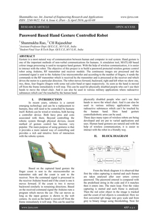
- 1. Shanmukha rao. Int. Journal of Engineering Research and Applications www.ijera.com ISSN: 2248-9622, Vol. 6, Issue 4, (Part - 3) April 2016, pp.63-69 www.ijera.com 63|P a g e Password Based Hand Gesture Controlled Robot 1 Shanmukha Rao, 2 CH Rajasekhar 1 Assistant Professor Dept. Of E.C.E., M.V.G.R., India 2 Student Final Year B.Tech Dept. Of E.C.E.,M.V.G.R., India ABSTRACT Gesture is a most natural way of communication between human and computer in real system. Hand gesture is one of the important methods of non-verbal communications for humans. A simulation tool, MATLAB based colour image processing is used to recognize hand gesture. With the help of wireless communication, it is easier to interact with the robot. The objective of this project is to build a password protected wireless gesture control robot using Arduino, RF transmitter and receiver module. The continuous images are processed and the command signal is sent to the Arduino Uno microcontroller and according to the number of fingers, it sends the commands to the RF transmitter which is received by the transmitter and is processed at the receiver end which drives the motor to a particular direction. The robot moves forward, backward, right and left when we show one, two, three, four fingers (fingers with some red color band or tape) respectively. As soon as the hand is moved off from the frame immediately it will stop. This can be used for physically disabled people who can’t use their hands to move the wheel chair. And it can also be used in various military applications where radioactive substances which can’t be touched by the human hand. I. INTRODUCTION In recent years, robotics is a current emerging technology and can be a replacement to humans, they still need to be controlled by humans itself. Robots can be wired or wireless, both having a controller device. Both have pros and cons associated with them. Beyond controlling the robotic system through physical devices, recent method of gesture control has become very popular. The main purpose of using gestures is that it provides a more natural way of controlling and provides a rich and intuitive form of interaction with the robotic system. Based on the captured hand gesture the finger count is sent to the microcontroller on transmitter side and the count is sent to the receiver. Now the command signal is processed in the receiver Arduino board and if the count is one it moves forward. If the count is two it moves backword similarly in remaining directions. Based on the received command signal the Arduino runs a program which moves the car. The car moves as long as the input gesture is shown to the web camera. As soon as the hand is moved off from the frame immediately it will stop. This can be used for physically disabled people who can’t use their hands to move the wheel chair. And it can also be used in various military applications where radioactive substances which can’t be touched by the human hand. Here hand gesture controlledrobotic arms can be used. These days many types of wireless robots are being developed and are put to varied applications and uses. Human hand gestures are natural and with the help of wireless communication, it is easier to interact with the robot in a friendly way. II. BLOCK DIAGRAM From the block diagram it is observed that first the video capturing is started and each frames are taken analysed after user enters correct password. The password entered is compared with the predefined string in the code and if it matches then it enters into. The main loop. First the video capturing is started and each frame is analysed. Then the red color object in the image is tracked and the count of red objects is considered. Here we first converted rgb image into grey scale and from grey to binary image using thresholding. Now for RESEARCH ARTICLE OPEN ACCESS
- 2. Shanmukha rao. Int. Journal of Engineering Research and Applications www.ijera.com ISSN: 2248-9622, Vol. 6, Issue 4, (Part - 3) April 2016, pp.63-69 www.ijera.com 64|P a g e each count a number is assigned and that number is sent to the Arduino at the transmitter side using serial communication. Now that signal is transmitted. At the receiver based on the command signal the motors and driven. Here 433Mhz transmitter and receiver is used for transmission and reception. It can be simply programmed using Arduino Uno board. III. WHY GESTURE Gesture recognition enables humans to communicate with the machine (HMI) and interact naturally without any mechanical devices. Using the concept of gesture recognition, it is possible to point a finger at the computer screen so that the cursor will move accordingly. This could potentially make conventional input devices such as mouse, keyboards and even touch- screens redundant. Gesture recognition can be conducted with techniques from computer vision and processing. The literature includes ongoing work in the computer vision field on capturing gestures or more general human pose and movements by cameras connected to a computer. In computer interfaces, two types of gestures are distinguished. consider online gestures, which can also be regarded as direct manipulations like scaling and rotating. In contrast, offline gestures are usually processed after the interaction is finished; e. g. a circle is drawn to activate a context menu. IV. APPLICATIONS In the near future, gesture recognition technology will routinely add yet another dimension to human interactions with consumer electronic devices -- such as PCs, media tablets and smartphones. Camera-based tracking for gesture recognition has actually been in use for some time. Leading video game consoles -- Microsoft’s Xbox and Sony’s PlayStation -- both have gesture recognition built-in; known as Kinect and PlayStation Eye respectively. These devices are in their seventh and eighth generation. However, several challenges remain for gesture recognition technology for mobile devices, including effectiveness of the technology in adverse light conditions, variations in the background, and high power consumption. Mostly in military application, industrial robotics, construction vehicles in civil side, medical application for surgery. In this field it is quite complicated to control the robot or particular machine with remote or switches, sometime the operator may get confused in the switches and button itself, so a new concept is introduced to control the machine with the movement of hand which will simultaneously control the movement of robot. Gesture in military applications For handicapped patients Some patients cannot control the wheelchair with their arms. The wheelchair is operated with the help of gestures that is simply counting the fingers, which in turn controls the wheelchair with the help of hand gesture. The wheelchair moves front, back, right and left. Due to which disabled and partially paralyzed patient can freely move. Gesture Controlled Wheel Chair
- 3. Shanmukha rao. Int. Journal of Engineering Research and Applications www.ijera.com ISSN: 2248-9622, Vol. 6, Issue 4, (Part - 3) April 2016, pp.63-69 www.ijera.com 65|P a g e Components used in this project: 1) Web Cam 2) Arduino Uno (microcontroller board) 3) 433 MHz RF transmitter and receiver 4) L293D motor driver IC 5) Chassis and wheels 6) DC motors 7) PC installed with mat lab and Arduino software CBIR (Content-Based Image Retrieval) is the process of retrieving images from a database or library of digital images according to the visual content of the images. In other words, it is the retrieving of images that have similar content of colours, textures or shapes. Images have always been an inevitable part of human communication and its roots millennia ago. Images make the communication process more interesting, illustrative, elaborate, understandable and transparent In CBIR system, it is usual to group the image features in three main classes: colour, texture and shape. Ideally, these features should be integrated to provide better discrimination in the comparison process. Colour is by far the most common visual feature used in CBIR, primarily because of the simplicity of extracting colour information from images. To extract information about shape and texture feature are much more complex and costly tasks, usually performed after the initial filtering provided by colour features. Many applications require simple methods for comparing pairs of images based on their overall appearance. For example, a user may wish to retrieve all images similar to a given image from a large database of images. Color histograms are a popular solution to this problem, the histogram describes the gray-level or color distribution for a given image, they are computationally efficient, but generally insensitive to small changes in camera position. Color histograms also have some limitations. A color histogram provides no spatial information; it merely describes which colors are present in the image, and in what quantities. In addition, color histograms are sensitive to both compression artifacts and changes in overall image brightness. For the design of histogram based method the main things we require are appropriate color space, a color quantization scheme, a histogram representation, and a similarity metric. A digital image in this context is a set of pixels. Each pixel represents a color. Colors can be represented using different color spaces depending on the standards used by the researcher or depending on the application such as Red-Green-Blue (RGB), Hue-Saturation-Value (HSV), YIQ or YUV etc. V. IMAGE CONVERSION It is also known as an RGB image. A true color image is an image in which each pixel is specified by three values one each for the red, blue, and green components of the pixel scalar. M by-n- by-3 array of class uint8, uint16, single, or double whose pixel values specify intensity values. For single or double arrays, values range from [0, 1]. For uint8, values range from [0, 255]. For uint16, values range from [0, 65535]. It is also known as an intensity, gray scale, or gray level image. Array of class uint8, uint16, int16, single, or double whose pixel values specify intensity values. For single or double arrays, values range from [0, 1]. For uint8, values range from [0,255]. For uint16, values range from [0, 65535]. For int16, values range from [-32768, 32767]. RGB to GREY scale conversion: Red color has more wavelength of all the three colors, and green is the color that has not only less wavelength then red color but also green is the color that gives more soothing effect to the eyes. It means that to decrease the contribution of red color, and increase the contribution of the green color, and put blue color contribution in between these two. So the new equation that form is: New grayscale image = ((0.3 * R) + (0.59 * G) + (0.11 * B)). According to this equation, Red has contribute 30%, Green has contributed 59% which is greater in all three colors and Blue has contributed 11%. Applying this equation to the image, we get this
- 4. Shanmukha rao. Int. Journal of Engineering Research and Applications www.ijera.com ISSN: 2248-9622, Vol. 6, Issue 4, (Part - 3) April 2016, pp.63-69 www.ijera.com 66|P a g e What is Arduino: Arduino is an open-source prototyping platform based on easy-to-use hardware and software. Arduino boards are able to read inputs - light on a sensor, a finger on a button, or a Twitter message - and turn it into an output - activating a motor, turning on an LED, publishing something online. You can tell your board what to do by sending a set of instructions to the microcontroller on the board. To do so you use the Arduino programming language (based on Wiring), and the Arduino Software (IDE), based on Processing. Over the years Arduino has been the brain of thousands of projects, from everyday objects to complex scientific instruments. A worldwide community of makers - students, hobbyists, artists, programmers, and professionals - has gathered around this open-source platform, their contributions have added up to an incredible amount of accessible knowledge that can be of great help to novices and experts alike. Arduino Uno R3 VI. AURDUINO MICRO- CONTROLLER A micro-controller is a small computer on a single integrated circuit containing a processor core, memory, and programmable input/output peripherals. The important part is that a micro- controller contains the processor (which all computers have) and memory, and some input/output pins that can control. (often called GPIO - General Purpose Input Output Pins). The Arduino Uno is a microcontroller board based on the ATmega328 (datasheet). It has 14 digital input/output pins (of which 6 can be used as PWM outputs), 6 analog inputs, a 16 MHz ceramic resonator, a USB connection, a power jack, an ICSP header, and a reset button. It contains everything needed to support the microcontroller; simply connect it to a computer with a USB cable or power it with a AC-to-DC adapter or battery to get started. The Uno differs from all preceding boards in that it does not use the FTDI USB-to-serial driver chip. Instead, it features the Atmega16U2 (Atmega8U2 up to version R2) programmed as a USB-to-serial converter. SPECIFICATIONS: Microcontroller : ATmega328 Operating Voltage : 5V Input Voltage (recommended) : 7-12V Input Voltage (limits) : 6-20V Digital I/O Pins : 14 Analog Input Pins : 6 DC Current per I/O Pin : 40 mA DC Current for 3.3V Pin : 50 mA Flash Memory : 32 KB (ATmega328) of which 0.5 KB used by bootloader SRAM : 2 KB EEPROM : 1 KB Clock Speed : 16 MHz 6.2 Matlab Functions used: 1. FramesPerTrigger: Specify number of frames to acquire per trigger using selected video source Description: The FramesPerTrigger property specifies the number of frames the video input object acquires each time it executes a trigger using the selected video source. When the value of the FramesPerTrigger property is set to Inf, the object keeps acquiring frames until an error occurs or you issue a stop command. 2. Returned Color Space: Specify color space used in MATLAB. Description: The ReturnedColorSpace property specifies the color space you want the toolbox to use when it returns image data to the MATLAB® workspace. This is only relevant when you are accessing acquired image data with the getsnapshot, getdata, and peek data functions. 3. Bwareaopen: Remove small objects from binary image. Syntax BW2 = bwareaopen(BW, P) BW2 = bwareaopen(BW, P, conn) Description: BW2 = bwareaopen(BW, P) removes from a binary image all connected components (objects) that have fewer than P pixels, producing another binary image, BW2. This operation is known as an area opening. The default connectivity is 8 for two dimensions, 26 for three dimensions, and conndef(ndims(BW), 'maximal') for higher dimensions. BW2 = bwareaopen(BW, P, conn) specifies the desired connectivity. conn can have any of the following scalar values. 4. bwlabel: Label connected components in 2-D binary image. Syntax L = bwlabel(BW, n)
- 5. Shanmukha rao. Int. Journal of Engineering Research and Applications www.ijera.com ISSN: 2248-9622, Vol. 6, Issue 4, (Part - 3) April 2016, pp.63-69 www.ijera.com 67|P a g e [L, num] = bwlabel(BW, n) Description: L = bwlabel(BW, n) returns a matrix L, of the same size as BW, containing labels for the connected objects in BW. The variable n can have a value of either 4 or 8, where 4 specifies 4- connected objects and 8 specifies 8-connected objects. If the argument is omitted, it defaults to 8. The elements of L are integer values greater than or equal to 0. The pixels labeled 0 are the background. The pixels labelled 1 make up one object; the pixels labeled 2 make up a second object; and so on. [L, num] = bwlabel(BW, n) returns in num the number of connected objects found in BW. The functions bwlabel, bwlabeln, and bwconncomp all compute connected components for binary images. bwconncomp replaces the use of bwlabel and bwlabeln. It uses significantly less memory and is sometimes faster than the other functions. 5. graythresh Global image threshold using Otsu's method Syntax level = graythresh(I) [level EM] = graythresh(I) Description: level = graythresh(I) computes a global threshold (level) that can be used to convert an intensity image to a binary image with im2bw. level is a normalized intensity value that lies in the range [0, 1]. The graythresh function uses Otsu's method, which chooses the threshold to minimize the intraclass variance of the black and white pixels. Multidimensional arrays are converted automatically to 2-D arrays using reshape. The graythresh function ignores any nonzero imaginary part of I. [level EM] = graythresh(I) returns the effectiveness metric, EM, as the second output argument. The effectiveness metric is a value in the range [0 1] that indicates the effectiveness of the thresholding of the input image. The lower bound is attainable only by images having a single gray level, and the upper bound is attainable only by two-valued images. 6. im2bw: Convert image to binary image, based on threshold. Syntax BW = im2bw(I, level) BW = im2bw(X, map, level) BW = im2bw(RGB, level) DescriptionBW = im2bw(I, level) converts the grayscale image I to a binary image. The output image BW replaces all pixels in the input image with luminance greater than level with the value 1 (white) and replaces all other pixels with the value 0 (black). Specify level in the range [0,1]. This range is relative to the signal levels possible for the image's class. Therefore, a level value of 0.5 is midway between black and white, regardless of class. To compute the level argument, you can use the function graythresh. If you do not specify level, im2bw uses the value 0.5. BW = im2bw(X, map, level) converts the indexed image X with colormap map to a binary image. BW = im2bw(RGB, level) converts the truecolor image RGB to a binary image. If the input image is not a grayscale image, im2bw converts the input image to grayscale, and then converts this grayscale image to binary by thresholding. 7. imsubtract: Subtract one image from another or subtract constant from image Syntax Z = imsubtract(X,Y) Description: Z = imsubtract(X,Y) subtracts each element in array Y from the corresponding element in array X and returns the difference in the corresponding element of the output array Z. X and Y are real, nonsparse numeric arrays of the same size and class, or Y is a double scalar. The array returned, Z, has the same size and class as X unless X is logical, in which case Z is double. If X is an integer array, elements of the output that exceed the range of the integer type are truncated, and fractional values are rounded. 8. medfilt2: 2-D median filtering Syntax B = medfilt2(A, [m n]) B = medfilt2(A) B = medfilt2(A, 'indexed', ...) B = medfilt2(..., padopt) Description: Median filtering is a nonlinear operation often used in image processing to reduce "salt and pepper" noise. A median filter is more effective than convolution when the goal is to simultaneously reduce noise and preserve edges. B = medfilt2(..., padopt) controls how the matrix boundaries are padded. padopt may be 'zeros' (the default), 'symmetric', or 'indexed'. If padopt is 'symmetric', A is symmetrically extended at the boundaries. If padopt is 'indexed', A is padded with ones if it is double; otherwise it is padded with zeros. 9. rgb2gray: Convert RGB image or colormap to grayscale Syntax I = rgb2gray(RGB)
- 6. Shanmukha rao. Int. Journal of Engineering Research and Applications www.ijera.com ISSN: 2248-9622, Vol. 6, Issue 4, (Part - 3) April 2016, pp.63-69 www.ijera.com 68|P a g e newmap = rgb2gray(map) Description: I = rgb2gray(RGB) converts the truecolor image RGB to the grayscale intensity image I. rgb2gray converts RGB images to grayscale by eliminating the hue and saturation information while retaining the luminance. newmap = rgb2gray(map) returns a grayscale colormap equivalent to map. P.code: It is password protected as only the user with the right password can access the robot and others can’t. The program is converted in to pseudocode P-CODE in order to protect the source code and password in the program. The P-files are much smaller than a zipped version of the M-files. This seems to imply, that the P-files are a kind of byte coded. For large M-files with 10'000th of lines opening the P-file the first time is faster than for the M-file. But this can be an effect of the file size. P-code files are encrypted and are very hard to decrypt and find out original source code. VII. WORKING In this project first using web camera capturing the video is initiated and then each frame obtained is analysed using image processing techniques. In this project Content based image retrieval is used in which only color of the object is considered. Now Putting some red color on the fingers the fingers are shown to the web camera. From each frame it analyses number of red color objects and then it will make a count. Based on the count Matlab sends a command to the Arduino microcontroller which is connected to the usb port of the computer. To this Arduino board a 433MHZ RF transmitter is connected. Now based on the received command by the Arduino Uno microcontroller it will use transmitter to transmit the signal to the robot car. Now at the receiver Arduino uno is connected to the 433Mhz receiver and upon the received value the microcontroller analyses the code and runs the DC motors accordingly which are connected to the motor driver ic L293D. VIII. RESULTS First upload the transmitter program in the Arduino board which is connected to the personal computer. Now upload the receiver program on the Arduino board which is connected to the robot car. Now open Matlab software which is installed on your personal computer.Open the Matlab code and run the program. Now based on the input shown to the web cam (number of fingers) the robot car moves in that direction. It is shown below, When one finger is shown to the webcam it moves in forward direction. Figure 1: Car moving in forward direction When two fingers are shown to the webcam it will move in backward direction. Figure 2: Car moving in backward direction When Three fingers are shown to the webcam it will move towards left side. Figure 3: Car moving in left direction
- 7. Shanmukha rao. Int. Journal of Engineering Research and Applications www.ijera.com ISSN: 2248-9622, Vol. 6, Issue 4, (Part - 3) April 2016, pp.63-69 www.ijera.com 69|P a g e When four fingers are shown to the webcam then it will move towards right side. Figure 4: Car moving in right direction From the above pictures it is clearly observed that based on the input given to the web cam the robot direction changes. The robot will move in particular direction as long as the input gesture is shown to the webcam. If there is no input shown to the webcam, then immediately the robot will stop moving. IX. CONCLUSION In this project the robot is controlled by using hand gestures. These gestures are given as input to the web camera which is connected to the personal computer. The Matlab code analyses the finger count and it sends a command signal to the microcontroller which is connected to the personal computer via USB. Using serial communication, the command signal is received to the microcontroller and the signal is transmitted. At the receiver end the microcontroller receives the signal and the microcontroller analyses the signal based on the gesture shown the wheels of the robot car are rotated. For example, if one finger is shown it moves in forward direction and if two fingers are shown it moves in backword direction and if three fingers are shown it moves in left direction and if four fingers are shown it moves in right direction. To stop the robot from moving simply don’t show any gesture to the web camera. This project is just a prototype for gesture controlled wheel chair for physically disabled people. It can be also used in nuclear plants where radioactive material can be handled by using a hand gesture controlled robotic arm. REFERENCES [1]. Design and Implementation of a Wireless Gesture Controlled Robot International Journal of Computer Applications (0975 – 8887) Volume 79 – No 13, October 2013. [2]. Hand gesture Based Direction Control of robocar using Arduino Microcontroller. International journal of recent technology and engineering(IJRTE) ISSN: 2277- 3878, Volume-3 Issue-3, July 2014. [3]. Implementation of a Wireless Gesture Controlled Robotic Arm. International Journal of Innovative Research in Computer and Communication Engineering (An ISO 3297: 2007 Certified Organization) Vol. 3, Issue 1, January 2015 Ch. Rajasekhar: pursuing B.TECH final year department of ECE from MVGR college of engineering in 2016. He is a member of IEEE student chapter. N. Shanmukharao: completed his, B.Tech from Jntu, Hyderabad in 2004 and M.Tech from andhra university now he is working as assistant professor, dept. of ece, mvgrce, Vijayanagaram. He has 11 years of experience in teaching. He has published 3 general papers. Research areas: 1. Signal processing, Image processing and Communication Systems.