SlideShare ist ein Scribd-Unternehmen logo
1 von 14
Inductors
ELECTROMAGNETS AND GENERATORS
The reader probably remembers from previous courses in general science that an electric current
going through a wire will produce magnetism. The "magnetic field" is around the wire,
somewhat like an invisible tube. This is shown diagrammatically by the two circles at the upper
left of Fig. 10.1. When the wire is coiled, as at the right-hand side of the figure, the fields line up
to make a
Magnetic
Fields
"donut" or "toroid" of magnetic fields, much stronger than the fields around the single wire
portions.
If an iron rod (not shown in the diagram) is poked vertically down through the coil, the fields
can go through that iron much easier than through air or vacuum.
103
104 10. Inductors
The ease of producing a strong field is called "permeability," and it is somewhat similar to the
"dielectric constant" described on page 92. Iron is easily "polarized" magnetically, because it
has many "unpaired" electrons that are spinning. An electron spinning generates a small
magnetic field of its own. The spins can be lined up in the same direction, if they are put in a
field such as the one from the wire. In some ways this is similar to the charges lining up inside
the ceramic "dielectric" shown on page 91, thus raising the capacitance.
Of course, an iron core plus a coil of wire can be an "electromagnet." When the current is
first turned on, the field suddenly expands, from zero to whatever the final size will be at the
maximum current.
The reader probably remembers, also, that if a second wire is moved through a stationary
magnetic field, or if the field is moved across a stationary wire, either way, a new voltage will be
generated in that second wire. This is the principle of the "electric generator," which is used to
make most of the electricity that comes to our houses and factories. A convenient concept is that
"lines of magnetic field are being cut by the wire." (The field really varies smoothly with
distance, and it is not grainy like wood. But for convenience we imagine lines, where the more
lines, the stronger the field.) A higher voltage will be generated if more of these conceptual
"lines" are being cut per second.
If there are two coils, both stationary, as in Fig. 10.2, and an electric current is suddenly
turned on in the left-hand coil, the magnetic field lines will quickly expand from zero to the final
size, and they will get "cut" very fast by the stationary wires of the right-hand coil. Thus a high
voltage will be generated in that coil.
If the current in the left-hand ("primary") coil is turned off suddenly, the field lines will be
cut as they collapse back to zero size, but in the opposite direction. The voltage in the right-hand
"secondary" coil will be generated with opposite polarity. (It could be a high voltage, if the turn-
off is fast enough.) If alternating current is put through the primary, then ac voltage will appear
in the secondary, and this of course is a typical use of the "transformer."
10. Inductors 105
If there are more turns in the secondary coil, each turn is a little voltage generator in series
with the others, so a higher voltage will appear across the terminals of the secondary. However,
the amount of power coming out must be the same as what goes in, because power is energy per
time (see the bottom of page 16), and energy can not be made or destroyed — it can only be
changed in its form. Since power is voltage times current (eqn. 2.8 on page 17), if there is a
higher voltage in the secondary than in the primary, then there must be a lower current, in order
for the energy per second to be constant. These are in direct proportion to the ratio of turns,
primary versus secondary.
On the other hand, if there are fewer turns in the secondary than in the primary, then there
will be a lower voltage. However, more current could then be gotten from the secondary, again
depending on the ratio of turns. This is analogous to a mechanical lever, where higher speed can
only be at lower force.
EXPERIMENTS
Transformers
Ordinarily, the primary coil of the transformer used in this course would be plugged into a 120 V
ac wall socket, and only 12 volts of ac would be available in the secondary, because that has ten
times fewer turns than the primary has. Thus, this transformer is usually in a "step-down" mode,
and in fact it was used that way in the optional experiment on page 98 of the previous chapter.
If the circuit of Fig. 10.2 on the previous page is assembled with the 9 volts going into the
primary (two heavily insulated black wires), it will still be used in the "step-down" mode, and the
neon bulb will not light when hooked up to the secondary (lightly insulated yellow wires),
because it requires much more than 9 volts, and instead it will probably be getting less.
(Actually, it could be lit if the battery was connected or disconnected fast enough to make up for
the unfavorable ratio of turns, but probably neither operation can be done fast enough here.)
The neon bulb will flash brightly if the battery is connected to the original secondary
(yellow-insulated wires of the transformer) and then suddenly disconnected, and the bulb is
attached to the original primary (thicker wires with black insulation), because everything is
favorable for a high voltage output— the step-up, and a fast current decrease in the primary.
There will be less current out, but it only takes a very low current to operate the neon bulb, as
was seen on page 6 of Chapter 1. (Note that the ignition coil in an automobile works this way,
but with far more turns in the secondary. With not so many turns, it is used in "switching power
supplies," including "inverters" that change dc to ac.)
106 10. Inductors
Autotransformers and Inductors
Figure 10.3 shows only the 12 volt side of the transformer being used, and the 9 V dc is going to
one end (yellow) plus the "center tap" (thin black insulation). The experimenter should attach the
oscilloscope with the vertical being voltage (CH2/Y), versus the horizontal being time
(TIME/DIV = 0.1 s) hookup. The input MODE is CH2, the trigger MODE is AUTO, and the
TRIGGER SOURCE is VERT (similar to pages 76 and 77). The VOLTS/DIV can start out at
about 1 but be changed as needed, including rotating the central VARIABLE knob.
As usual in this course, there is no real switch, and a clip lead is simply touched for a short
time ("momentarily") to a wire or terminal, to put a short burst of current through half of the "12
volt" coil (ordinarily the secondary, but acting as a primary here). When the current is suddenly
increased, a downward spike appears on the scope, showing that the "top" half of the center-
tapped coil has
10. Inductors 107
negative voltage going to the scope hook, and positive going to its grounded clip lead. This is
just the opposite of the voltages on the "bottom" half of the coil. Therefore the two halves tend to
cancel each other, whenever we try to suddenly increase the current, which tends to prevent the
current from increasing quickly.
The next step is to suddenly "open" the "switch," and an upward spike appears, meaning that
a voltage has been generated in the top half-coil that adds to the bottom half's voltage. The
overall action therefore tends to prevent the current from stopping quickly.
COMMENT
Several things can go wrong with this experiment, although it should be possible to make it
produce the exact result described above. First of all, the experimenter might verify that an
"upward" spike on the scope display does indeed mean a positive voltage on the BNC cable's
hook. (Be sure that the NORM / INV button has not been pushed accidentally.) This can be
checked by attaching the hook and ground clip directly to the battery, with nothing else
attached, and seeing whether the bright spot in the display goes upward. (In fact, the
experimenter should get in the habit of "checking out" the scope like this, whenever results do
not match expectations.) Secondly, sometimes a capacitance inside the scope gets charged up
and then will not respond for a second trial. If that seems to be the case, discharge it before
each new trial, by momentarily touching the hook to the ground clip. Thirdly, sometimes
safety devices inside the scope prevent spikes of certain polarities. If the downward spike
appears but the upward one will not, try reversing the polarity of the battery, and also pushing
the NORM / INV button. Then both spikes should become visible, in this doubly inverted
mode. Another point is that very little current flows into the scope, because of its extremely
high "input impedance." If a low resistance such as an ammeter is attached to the top half-coil,
then considerable current will flow, and this will make its own magnetic field, which interacts
with the field of the bottom half-coil in a complex manner. The voltages of the two halves
might then become additive and not cancel.
The action of the top and bottom halves of the coil is similar to the action of the primary and
secondary of an ordinary transformer, except that in the above experiment they are parts of the
same coil, and they have the same numbers of turns. In some cases it is desirable to use just one
continuous coil with a "tap," but not necessarily at the center, and in fact it can be movable, to
provide varying voltages. This is called an "autotransformer," and it is often used to convert 120
volts to either lower or higher voltages, all ac, for operating small heaters or
108 10. Inductors
stirring motors in chemical laboratories. The brand name of one such commonly used device is
Variac®
.
LESSON
The main idea of this experiment is that a fast-changing current in a coil will "induce" an
opposite voltage in a nearby coil, and also in itself. The latter effect is what causes an
inductor to resist change in the current going through it, which produces the electrical analog
of mechanical inertia, including the "inductive kick" seen in Chapter 1. It does not have to be
center-tapped at all, and in fact it usually is not. When the current changes fast, every turn of a
coil induces an opposing voltage in each other turn, and this causes "inductance." By
comparison, direct current goes through an inductor with no more resistance than it would
have in a straight wire with no metal core — in other words, easily. But the higher the
frequency (faster change in direction), the less current gets through an inductive coil,
especially if it has an iron core to enhance the magnetic action.
A mechanical analog of an inductor is shown in Fig. 10.4. As briefly mentioned on the very
first page of Chapter 1, an inductor acts like a heavy piston inside a water pipe, tending to
prevent fast changes in flow, either increases or decreases. There is very little resistance to
steady water flow, similar to dc electricity in an inductor. On the other hand, high speed changes
in direction would meet great resistance, similar to high frequency ac in the same inductor.
Pipe
Fig. 10.4 A piston analog of an inductor, with an O-ring seal at each end.
Shorted Additional Coil
The experimenter should construct the circuit of Fig. 10.5 on the next page. At first, the wires
shown as dashed lines are not connected. The experiment is done as on page 7 of the first
chapter, where the "switch" is opened suddenly, and there is a bright flash in the neon bulb. Then
the short circuiting clip lead (dashed line in the diagram) is attached to the transformer's 120 volt
coil (heavily insulated black wires or soldered-on power cord). Now when the switch is opened,
there is no neon flash. What is happening is that current is induced in the "shorted" coil, as the
battery current suddenly decreases. This new current has a magnetic field
10. Inductors 109
that tends to stop the current faster, whenever the battery current decreases. That of course is the
opposite of tending to keep it going, as the coil turns on the other side of the transformer do to
each other.
9 Volts
There is a very important consequence of this behavior. First of all, if there is no short
circuit, then the left side has a high inductance, which resists the flow of ac current. (Of course,
we are not using true 60 Hz ac here, but transformers usually do.) Therefore, when there is no
output (no "short" on the right-hand side, as shown here), very little current flows into the input,
and the system is just "idling." A transformer can be plugged into a source of ac and hardly draw
any power under such conditions, while it is waiting to be used. When a "load" (such as an
electric motor) is later attached to the output side, current flows through both sides, and of course
power is then being drawn from the source, possibly a wall socket. It is only drawn from the
input side as it is used at the output side, so it does not waste power if it is not being used.
110 10. Inductors
If there is an extreme case such as a short circuit in the output, as we intentionally produced
here in order to make the effects easy to observe, then there will also be a short circuit at the
input. This could burn out either side.
Something similar happens with an electric motor (Fig. 20.1 on page 215), which can spin at
high efficiency if it is not being used, but which draws far more current if it is slowed down by
heavy use. It will become a short circuit and burn out, just like the input side here, if an
excessive mechanical load completely prevents rotation. The reason, briefly, is that a motor
rotating fast has high frequency ac going through its inductors, and the inductors (various coils)
inside the motor tend to prevent the current from changing direction so fast. Therefore, very
little ac current flows. When the motor slows down, the frequency (speed of direction change)
slows, and more current can get through. If the motor stops, it is like dc going through its
internal inductors, and too much current flows. This will be explained further in the chapter on
motors.
Snubbers
Disconnecting the short circuit wire, and then opening the switch again will make a spark and
also a neon flash at the "switch" itself. This spark is very hot and can do a lot of damage to
whatever real switch (as contrasted to our make-believe "switch") is actually used to turn off a
large transformer or motor or other inductor. In order to prevent the spark, a "snubber" can be
used (sometimes called a "spark suppressor" or "spike suppressor"). Attaching a clip lead where
the upper-left dashed line is shown in Fig. 10.5, and thus putting the capacitor and resistor across
the "switch," the capacitor will absorb the inductive kick and prevent the high voltage spark. The
inductive current will still flow for a short time after the switch is opened suddenly, but it goes
into the capacitor instead of making a spark. There is no longer enough high voltage to light the
neon bulb, which further proves that the snubber is doing its job.
The 100 ohms is high enough to prevent excessive initial current from damaging the
capacitor, but low enough to soak up the inductive kick. If the capacitor is used many times in a
row, it will eventually charge up and then fail to work for snubbing the sparks. In that case, a
1,000 ohm resistor should be put across the capacitor to slowly discharge it. (In most real
equipment, the capacitors are only about 100 microfarads (mfd), and they have a resistor for
discharging.) There are other types of spark snubbers, which will be explained in the chapter on
diodes.
10. Inductors 111
Symbols
Another way to draw coils is shown in Fig. 10.6. It is often used in modern publications,
because it is easier to draw than complete spirals.
The two black dots on the left-hand transformer indicate that, at a certain time, the current is
coming "upwards," out of both sides. Since alternating current goes both "up" (as shown here),
and also "down" a fraction of a second later, it is pointless to say "+" or "-" and, instead, we
describe the left-hand transformer as "being in phase." In the right-hand transformer, the two
coils are wound differently from each other, so at any time when "positive" current is going "up"
in the primary coil, it is going "down" in the secondary. We describe this as "being 180 degrees
out of phase." (The reader might refer to Fig. 10.8 for further clarification.) The black dots are
only shown in those cases where this is an important item.
In Phase 180 Degrees Out of Phase
Voltage Versus Current
While the oscilloscope is still hooked up, the experimenter can change the circuitry to that of Fig.
10.7 (on the next page), which is the same as on page 97, except for the transformer primary
being substituted instead of the capacitor. The 120 volt coil of the transformer can be used here,
either with or without its long power cord. On the scope screen, the voltage (vertical) will be
observed to increase before the current (horizontal) increases. The VOLTS/DIV knobs may have
to be set for more sensitivity (lower voltages per display division), because even the multi-turn
120 volt winding will not have as much inductive effect as the 1,000 mfd capacitor had
capacitance effect. In this case, the voltage can be applied to the coil immediately, but the
current can not increase so fast, just like water pressure on a heavy piston can not get it up to full
speed instantly. An increase in current induces a high reverse voltage, so the initial current
increase is retarded in its timing.
112 10. Inductors
9 Volts
Fig. 10.7
Phase
As observed in the curve tracer experiment, the current lags the voltage, and the voltage is said to
lead the current, when an ac sine wave goes through an inductor. (Doing the experiment requires
two transformers, so it will not be performed here.) The relationship is shown in Fig. 10.8.
Actually, the pendulum on page 98
Fig. 10.8 Sine wave ac in an inductor, showing lead and lag.
10. Inductors 113
is more closely analogous to the inductors in this chapter than to the capacitors in the previous
chapter, but the general ideas of instantaneous ("leading") versus cumulative ("lagging")
behavior apply to both.
OPTIONAL
Current Versus Time
When the voltage is first applied, and the current builds up, that current follows the following
equation:
I = Imax ( 1 -e-t/τ
) (10.1)
where t is time and τ is the time constant, "tau" (the time when the current gets to about 2/3
of its maximum value). This is similar to the capacitor example on page 94, but with current
changing now instead of voltage. The curves also are similar, but with inductor current
substituted for capacitor voltage. The voltage itself is given by Ohm's law, V = IR. (For "e,"
see page 95.)
When the driving voltage is removed, the current decays according to:
I = Imax ( e-t/τ
) (10.2)
where τ is the time at which the current gets to about 1/3 of Imax .
Although τ = RC with capacitors (page 95), τ = L/R with inductors, where L is the
inductance. Thus a resistance tends to decrease the time constant with inductors, while it
increases it with capacitors.
The inductive kick, that is, the voltage generated by decreasing the current quickly, is V =
L[(current change) / (time change)]. Thus, the faster the change in current, the higher the
voltage that is generated, almost without limit.
Reactance
There is an inductive reactance, similar to the
capacitive reactance described on page 99. The
formula is XL = 2π fL (10.3)
where f is the frequency, and L is the inductance.
The unit of frequency, f, is the Hertz, named after the early scientist, Heinrich Hertz, and
the unit of inductance, L, is the Henry, named after the early scientist, Joseph Henry. The
vector diagram on page 101 can still be used to show the relationship between inductive
reactance, XL, and resistance, R, with the hypotenuse being the impedance, Z. Similarly, the
"loss" is the tangent of the angle, delta. The power factor for inductors is also R / Z, as on
page 101.
114 10. Inductors
Inductance
The value of the inductance, in units of microhenrys, can be calculated approximately from the
dimensions of the coil shown in Fig. 10.9, as follows:
µ (turns)2
(radius)2
L = (10.4)
9 (radius) + 10
(length)
where the radius and length are in inches. The Greek letter µ ("mu," pronounced "myoo") is the
relative permeability, compared to the permeability of vacuum. This would be essentially the µ
of the iron (or "ferrite" ceramic) core. (The µ of air is close to that of vacuum and is ignored in
air-core coils. See also page 268.) The symbol at the left, the circle with a sine wave inside,
stands for any source of
Radius
Length
alternating voltage or current, such as the output of a transformer or generator or oscillator. (The
latter will be covered in a later chapter.) The center-tap has no effect on the inductance, if it is
not attached to anything.
COMMENT
Inductors tend to be bulky and heavy, and in many cases they can be replaced by smaller,
lighter weight capacitors (as will be described later, on page 123). That is why, instead of
inductors, circuit designers try to use capacitors or "gyrators" (to be mentioned briefly on page
125).
10. Inductors 115
LOSSLESS CONTROL
Inductors decrease ac current by "reactance," similar to the way capacitors do (see last text
paragraph on page 102). If the inductor were perfect, and had no resistance, then no power would
be lost through heating ("dissipation"). Nearly perfect inductors are nearly lossless. For this
reason, the autotransformer described at the bottom of page 107 can decrease ac voltage and
current with very little wasted power. Also, a simple two-terminal "ballast" inductor, which is
not center-tapped, is often used to limit the current in fluorescent lights.
Another way to do this, as also mentioned on page 102, is by fast on-off switching. This is
done with SCR controllers, as will be described Chapter 21.
If a large rheostat is used, however, a great deal of power is wasted in the form of heat
dissipation. That method was used in old electrical equipment such as early electric railroad
engines and trolley cars, before it was realized that inductors could be used and even earlier,
when most electric power was dc.
SATURABLE CORES AND MAG-AMPS
As the alternating current input of a transformer increases, the output also increases, but it
reaches a maximum value when the core becomes "saturated" and can no longer increase its
magnetization. If the transformer is purposely operated under these conditions, the output will
be constant, even if the input varies a small amount. This is sometimes used to provide a
dependable, constant voltage to operate sensitive instruments, heaters, and other devices, and it is
called a "saturable core reactor" or a "constant voltage transformer." In newer equipment
designs, it has mostly been replaced by the semiconductor devices that will be described in
Chapter 15 (Fig. 15.6).
If a transformer is operated a little bit below saturation, and a small direct current is sent to a
third coil, this can be used to sharply change the output, by pushing the total magnetization up
into saturation. (None of the dc itself becomes part of the output — it only affects the ac, but it
is not part of it.) Then, by decreasing the dc a small amount, the iron core can become
unsaturated, and far more ac will go through, into the output. Thus a small dc signal can control
a large ac "throughput." This is called a "magnetic amplifier," or "mag-amp." It is used to
control high currents for heaters in older industrial furnaces, although SCRs are used instead, for
modern designs. The SCR and similar devices will be described in Chapter 21.
116 10. Inductors
EQUIPMENT NOTES
Components For Radio Shack
This Chapter Catalog Number
Battery, nine volts 23-653
Clip leads, 14 inch, one set. 278-1156C
Transformer, 120V to 12V, 450 ma, center tapped 273-1365A Resistor, 100 ohm, 10 or
1 watt 271-135 or 271-152A Potentiometer, 5K 271-1714 or 271-1720 Capacitor,
1000 mfd 272-1019 or 272-1032 Neon test light, 90 volts 22-102 or 272-707
Oscilloscope, Model OS-5020, LG Precision Co., Ltd., of Seoul, Korea

Weitere ähnliche Inhalte

Was ist angesagt?

Physics Project for class 12 isc Junction and diode
Physics Project for class 12 isc Junction and diodePhysics Project for class 12 isc Junction and diode
Physics Project for class 12 isc Junction and diodeIshani gupta Gupta
 
electromagnetic induction ( part 2 )
electromagnetic induction ( part 2 )electromagnetic induction ( part 2 )
electromagnetic induction ( part 2 )Priyanka Jakhar
 
Electromagnetic induction
Electromagnetic inductionElectromagnetic induction
Electromagnetic inductionDivyansh Thada
 
Electromagnetic induction
Electromagnetic inductionElectromagnetic induction
Electromagnetic inductionBahdah Shin
 
Electromagnetic induction and transformer
Electromagnetic induction and transformer Electromagnetic induction and transformer
Electromagnetic induction and transformer Nitish Prajapati
 
Electromagnetic Induction Class 12
Electromagnetic Induction Class 12 Electromagnetic Induction Class 12
Electromagnetic Induction Class 12 Self-employed
 
Presentation on Electromagnetic Induction
Presentation on Electromagnetic InductionPresentation on Electromagnetic Induction
Presentation on Electromagnetic InductionSaleh Ibne Omar
 
Oersteds principle
Oersteds principleOersteds principle
Oersteds principleKier Manait
 
3.2.1 electomagnetic induction
3.2.1   electomagnetic induction3.2.1   electomagnetic induction
3.2.1 electomagnetic inductionJohnPaul Kennedy
 
physics project on electromagnetic inducion
physics project on electromagnetic inducionphysics project on electromagnetic inducion
physics project on electromagnetic inducionpranav1645
 
Electromagnetism
ElectromagnetismElectromagnetism
ElectromagnetismChoong Hong
 
Electric circuits and networks Basics
Electric circuits and networks BasicsElectric circuits and networks Basics
Electric circuits and networks BasicsPradeepRaj
 
Magnetic boundary conditions 3rd 4
Magnetic boundary conditions 3rd 4Magnetic boundary conditions 3rd 4
Magnetic boundary conditions 3rd 4HIMANSHU DIWAKAR
 
Physics Investigatory Project
Physics Investigatory  ProjectPhysics Investigatory  Project
Physics Investigatory ProjectDIVYANSHU KUMAR
 

Was ist angesagt? (19)

Physics Project for class 12 isc Junction and diode
Physics Project for class 12 isc Junction and diodePhysics Project for class 12 isc Junction and diode
Physics Project for class 12 isc Junction and diode
 
Mutual induction
Mutual inductionMutual induction
Mutual induction
 
electromagnetic induction ( part 2 )
electromagnetic induction ( part 2 )electromagnetic induction ( part 2 )
electromagnetic induction ( part 2 )
 
Magnetic flux
Magnetic fluxMagnetic flux
Magnetic flux
 
Electromagnetic induction
Electromagnetic inductionElectromagnetic induction
Electromagnetic induction
 
Electromagnetic induction
Electromagnetic inductionElectromagnetic induction
Electromagnetic induction
 
emi
emiemi
emi
 
Electromagnetic induction and transformer
Electromagnetic induction and transformer Electromagnetic induction and transformer
Electromagnetic induction and transformer
 
Electromagnetic Induction Class 12
Electromagnetic Induction Class 12 Electromagnetic Induction Class 12
Electromagnetic Induction Class 12
 
CURRENT ELECTRICITY
CURRENT ELECTRICITYCURRENT ELECTRICITY
CURRENT ELECTRICITY
 
Transformer(Class 12 Investigatory Project)
Transformer(Class 12 Investigatory Project)Transformer(Class 12 Investigatory Project)
Transformer(Class 12 Investigatory Project)
 
Presentation on Electromagnetic Induction
Presentation on Electromagnetic InductionPresentation on Electromagnetic Induction
Presentation on Electromagnetic Induction
 
Oersteds principle
Oersteds principleOersteds principle
Oersteds principle
 
3.2.1 electomagnetic induction
3.2.1   electomagnetic induction3.2.1   electomagnetic induction
3.2.1 electomagnetic induction
 
physics project on electromagnetic inducion
physics project on electromagnetic inducionphysics project on electromagnetic inducion
physics project on electromagnetic inducion
 
Electromagnetism
ElectromagnetismElectromagnetism
Electromagnetism
 
Electric circuits and networks Basics
Electric circuits and networks BasicsElectric circuits and networks Basics
Electric circuits and networks Basics
 
Magnetic boundary conditions 3rd 4
Magnetic boundary conditions 3rd 4Magnetic boundary conditions 3rd 4
Magnetic boundary conditions 3rd 4
 
Physics Investigatory Project
Physics Investigatory  ProjectPhysics Investigatory  Project
Physics Investigatory Project
 

Andere mochten auch

Digital Communications 3rd Quarter
Digital Communications 3rd QuarterDigital Communications 3rd Quarter
Digital Communications 3rd QuarterChoi Kyung Hyo
 
Principles of Communications
Principles of CommunicationsPrinciples of Communications
Principles of CommunicationsChoi Kyung Hyo
 
Digital Communications Midterm :D
Digital Communications Midterm :DDigital Communications Midterm :D
Digital Communications Midterm :DChoi Kyung Hyo
 
Safety management Chapters 6 and 7
Safety management Chapters 6 and 7Safety management Chapters 6 and 7
Safety management Chapters 6 and 7Choi Kyung Hyo
 
3rd qrtr p comm sc part 1
3rd qrtr p comm sc part 13rd qrtr p comm sc part 1
3rd qrtr p comm sc part 1Choi Kyung Hyo
 
Safety Management Chapter 8
Safety Management Chapter 8Safety Management Chapter 8
Safety Management Chapter 8Choi Kyung Hyo
 
10 elec3114
10 elec311410 elec3114
10 elec3114Vin Voro
 
02 elec3114
02 elec311402 elec3114
02 elec3114Vin Voro
 
Occupational safety and health for technologists, engineers
Occupational safety and health for technologists, engineersOccupational safety and health for technologists, engineers
Occupational safety and health for technologists, engineersMohd Hilmi
 
3rd qrtr p comm sc part 2
3rd qrtr p comm sc part 23rd qrtr p comm sc part 2
3rd qrtr p comm sc part 2Choi Kyung Hyo
 
Safety Management Chapter 9
Safety Management Chapter 9Safety Management Chapter 9
Safety Management Chapter 9Choi Kyung Hyo
 

Andere mochten auch (16)

Enggo5
Enggo5Enggo5
Enggo5
 
Diodes
DiodesDiodes
Diodes
 
Capacitors
CapacitorsCapacitors
Capacitors
 
Digital Communications 3rd Quarter
Digital Communications 3rd QuarterDigital Communications 3rd Quarter
Digital Communications 3rd Quarter
 
Filters and resonance
Filters and resonanceFilters and resonance
Filters and resonance
 
Principles of Communications
Principles of CommunicationsPrinciples of Communications
Principles of Communications
 
Digital Communications Midterm :D
Digital Communications Midterm :DDigital Communications Midterm :D
Digital Communications Midterm :D
 
Safety management Chapters 6 and 7
Safety management Chapters 6 and 7Safety management Chapters 6 and 7
Safety management Chapters 6 and 7
 
3rd qrtr p comm sc part 1
3rd qrtr p comm sc part 13rd qrtr p comm sc part 1
3rd qrtr p comm sc part 1
 
Safety Management Chapter 8
Safety Management Chapter 8Safety Management Chapter 8
Safety Management Chapter 8
 
10 elec3114
10 elec311410 elec3114
10 elec3114
 
02 elec3114
02 elec311402 elec3114
02 elec3114
 
3rd qrtr +++
3rd qrtr +++3rd qrtr +++
3rd qrtr +++
 
Occupational safety and health for technologists, engineers
Occupational safety and health for technologists, engineersOccupational safety and health for technologists, engineers
Occupational safety and health for technologists, engineers
 
3rd qrtr p comm sc part 2
3rd qrtr p comm sc part 23rd qrtr p comm sc part 2
3rd qrtr p comm sc part 2
 
Safety Management Chapter 9
Safety Management Chapter 9Safety Management Chapter 9
Safety Management Chapter 9
 

Ähnlich wie Inductors

BACK to BASIC 5.pdf
BACK to BASIC 5.pdfBACK to BASIC 5.pdf
BACK to BASIC 5.pdfEdgar Rios
 
Chapter 32
Chapter 32Chapter 32
Chapter 32mcfalltj
 
Basic electronics
Basic electronicsBasic electronics
Basic electronicsMrinal Pal
 
Electronics 01
Electronics 01Electronics 01
Electronics 01snakeaye
 
Basic Physics Regenerative Acceleration Generator Technology
Basic Physics Regenerative Acceleration Generator TechnologyBasic Physics Regenerative Acceleration Generator Technology
Basic Physics Regenerative Acceleration Generator TechnologyThane Heins
 
anery-Whats Diode
anery-Whats Diodeanery-Whats Diode
anery-Whats DiodeAnery rye
 
Electrical interview-questions-answers
Electrical interview-questions-answersElectrical interview-questions-answers
Electrical interview-questions-answersRaghavendra Kiran
 
Single phase power systems
Single phase power systemsSingle phase power systems
Single phase power systemsBibek Chouhan
 
Single phase power systems
Single phase power systemsSingle phase power systems
Single phase power systemsBibek Chouhan
 
Single phase power systems
Single phase power systemsSingle phase power systems
Single phase power systemsBibek Chouhan
 
project report on plc based load sharing
project report on plc based load sharingproject report on plc based load sharing
project report on plc based load sharingVivek Arun
 
Starting of fluorescent tube light by using inverter circuit instead of choke...
Starting of fluorescent tube light by using inverter circuit instead of choke...Starting of fluorescent tube light by using inverter circuit instead of choke...
Starting of fluorescent tube light by using inverter circuit instead of choke...IJERA Editor
 

Ähnlich wie Inductors (20)

BACK to BASIC 5.pdf
BACK to BASIC 5.pdfBACK to BASIC 5.pdf
BACK to BASIC 5.pdf
 
Chapter3
Chapter3Chapter3
Chapter3
 
Chapter 32
Chapter 32Chapter 32
Chapter 32
 
Basic electronics
Basic electronicsBasic electronics
Basic electronics
 
Chapter16
Chapter16Chapter16
Chapter16
 
Electronics 01
Electronics 01Electronics 01
Electronics 01
 
AC circuit
AC circuitAC circuit
AC circuit
 
Electronics 01
Electronics 01Electronics 01
Electronics 01
 
Basic Physics Regenerative Acceleration Generator Technology
Basic Physics Regenerative Acceleration Generator TechnologyBasic Physics Regenerative Acceleration Generator Technology
Basic Physics Regenerative Acceleration Generator Technology
 
anery-Whats Diode
anery-Whats Diodeanery-Whats Diode
anery-Whats Diode
 
Electrical interview-questions-answers
Electrical interview-questions-answersElectrical interview-questions-answers
Electrical interview-questions-answers
 
BASIC ELECTRICAL EMERSON EDUARDO RODRIGUES
BASIC ELECTRICAL EMERSON EDUARDO RODRIGUESBASIC ELECTRICAL EMERSON EDUARDO RODRIGUES
BASIC ELECTRICAL EMERSON EDUARDO RODRIGUES
 
Basic Physics
Basic PhysicsBasic Physics
Basic Physics
 
Single phase power systems
Single phase power systemsSingle phase power systems
Single phase power systems
 
Single phase power systems
Single phase power systemsSingle phase power systems
Single phase power systems
 
Single phase power systems
Single phase power systemsSingle phase power systems
Single phase power systems
 
Report on inverters
Report on invertersReport on inverters
Report on inverters
 
solenoid
solenoidsolenoid
solenoid
 
project report on plc based load sharing
project report on plc based load sharingproject report on plc based load sharing
project report on plc based load sharing
 
Starting of fluorescent tube light by using inverter circuit instead of choke...
Starting of fluorescent tube light by using inverter circuit instead of choke...Starting of fluorescent tube light by using inverter circuit instead of choke...
Starting of fluorescent tube light by using inverter circuit instead of choke...
 

Kürzlich hochgeladen

Putting the SPARK into Virtual Training.pptx
Putting the SPARK into Virtual Training.pptxPutting the SPARK into Virtual Training.pptx
Putting the SPARK into Virtual Training.pptxCynthia Clay
 
Durg CALL GIRL ❤ 82729*64427❤ CALL GIRLS IN durg ESCORTS
Durg CALL GIRL ❤ 82729*64427❤ CALL GIRLS IN durg ESCORTSDurg CALL GIRL ❤ 82729*64427❤ CALL GIRLS IN durg ESCORTS
Durg CALL GIRL ❤ 82729*64427❤ CALL GIRLS IN durg ESCORTSkajalroy875762
 
Escorts in Nungambakkam Phone 8250092165 Enjoy 24/7 Escort Service Enjoy Your...
Escorts in Nungambakkam Phone 8250092165 Enjoy 24/7 Escort Service Enjoy Your...Escorts in Nungambakkam Phone 8250092165 Enjoy 24/7 Escort Service Enjoy Your...
Escorts in Nungambakkam Phone 8250092165 Enjoy 24/7 Escort Service Enjoy Your...meghakumariji156
 
Cannabis Legalization World Map: 2024 Updated
Cannabis Legalization World Map: 2024 UpdatedCannabis Legalization World Map: 2024 Updated
Cannabis Legalization World Map: 2024 UpdatedCannaBusinessPlans
 
Falcon Invoice Discounting: Empowering Your Business Growth
Falcon Invoice Discounting: Empowering Your Business GrowthFalcon Invoice Discounting: Empowering Your Business Growth
Falcon Invoice Discounting: Empowering Your Business GrowthFalcon investment
 
JAJPUR CALL GIRL ❤ 82729*64427❤ CALL GIRLS IN JAJPUR ESCORTS
JAJPUR CALL GIRL ❤ 82729*64427❤ CALL GIRLS IN JAJPUR  ESCORTSJAJPUR CALL GIRL ❤ 82729*64427❤ CALL GIRLS IN JAJPUR  ESCORTS
JAJPUR CALL GIRL ❤ 82729*64427❤ CALL GIRLS IN JAJPUR ESCORTSkajalroy875762
 
Berhampur 70918*19311 CALL GIRLS IN ESCORT SERVICE WE ARE PROVIDING
Berhampur 70918*19311 CALL GIRLS IN ESCORT SERVICE WE ARE PROVIDINGBerhampur 70918*19311 CALL GIRLS IN ESCORT SERVICE WE ARE PROVIDING
Berhampur 70918*19311 CALL GIRLS IN ESCORT SERVICE WE ARE PROVIDINGpr788182
 
Berhampur CALL GIRL❤7091819311❤CALL GIRLS IN ESCORT SERVICE WE ARE PROVIDING
Berhampur CALL GIRL❤7091819311❤CALL GIRLS IN ESCORT SERVICE WE ARE PROVIDINGBerhampur CALL GIRL❤7091819311❤CALL GIRLS IN ESCORT SERVICE WE ARE PROVIDING
Berhampur CALL GIRL❤7091819311❤CALL GIRLS IN ESCORT SERVICE WE ARE PROVIDINGpr788182
 
Uneak White's Personal Brand Exploration Presentation
Uneak White's Personal Brand Exploration PresentationUneak White's Personal Brand Exploration Presentation
Uneak White's Personal Brand Exploration Presentationuneakwhite
 
New 2024 Cannabis Edibles Investor Pitch Deck Template
New 2024 Cannabis Edibles Investor Pitch Deck TemplateNew 2024 Cannabis Edibles Investor Pitch Deck Template
New 2024 Cannabis Edibles Investor Pitch Deck TemplateCannaBusinessPlans
 
Falcon Invoice Discounting: The best investment platform in india for investors
Falcon Invoice Discounting: The best investment platform in india for investorsFalcon Invoice Discounting: The best investment platform in india for investors
Falcon Invoice Discounting: The best investment platform in india for investorsFalcon Invoice Discounting
 
Kalyan Call Girl 98350*37198 Call Girls in Escort service book now
Kalyan Call Girl 98350*37198 Call Girls in Escort service book nowKalyan Call Girl 98350*37198 Call Girls in Escort service book now
Kalyan Call Girl 98350*37198 Call Girls in Escort service book nowranineha57744
 
Lundin Gold - Q1 2024 Conference Call Presentation (Revised)
Lundin Gold - Q1 2024 Conference Call Presentation (Revised)Lundin Gold - Q1 2024 Conference Call Presentation (Revised)
Lundin Gold - Q1 2024 Conference Call Presentation (Revised)Adnet Communications
 
Paradip CALL GIRL❤7091819311❤CALL GIRLS IN ESCORT SERVICE WE ARE PROVIDING
Paradip CALL GIRL❤7091819311❤CALL GIRLS IN ESCORT SERVICE WE ARE PROVIDINGParadip CALL GIRL❤7091819311❤CALL GIRLS IN ESCORT SERVICE WE ARE PROVIDING
Paradip CALL GIRL❤7091819311❤CALL GIRLS IN ESCORT SERVICE WE ARE PROVIDINGpr788182
 
Dr. Admir Softic_ presentation_Green Club_ENG.pdf
Dr. Admir Softic_ presentation_Green Club_ENG.pdfDr. Admir Softic_ presentation_Green Club_ENG.pdf
Dr. Admir Softic_ presentation_Green Club_ENG.pdfAdmir Softic
 
PARK STREET 💋 Call Girl 9827461493 Call Girls in Escort service book now
PARK STREET 💋 Call Girl 9827461493 Call Girls in  Escort service book nowPARK STREET 💋 Call Girl 9827461493 Call Girls in  Escort service book now
PARK STREET 💋 Call Girl 9827461493 Call Girls in Escort service book nowkapoorjyoti4444
 
Berhampur Call Girl Just Call 8084732287 Top Class Call Girl Service Available
Berhampur Call Girl Just Call 8084732287 Top Class Call Girl Service AvailableBerhampur Call Girl Just Call 8084732287 Top Class Call Girl Service Available
Berhampur Call Girl Just Call 8084732287 Top Class Call Girl Service Availablepr788182
 
joint cost.pptx COST ACCOUNTING Sixteenth Edition ...
joint cost.pptx  COST ACCOUNTING  Sixteenth Edition                          ...joint cost.pptx  COST ACCOUNTING  Sixteenth Edition                          ...
joint cost.pptx COST ACCOUNTING Sixteenth Edition ...NadhimTaha
 
Challenges and Opportunities: A Qualitative Study on Tax Compliance in Pakistan
Challenges and Opportunities: A Qualitative Study on Tax Compliance in PakistanChallenges and Opportunities: A Qualitative Study on Tax Compliance in Pakistan
Challenges and Opportunities: A Qualitative Study on Tax Compliance in Pakistanvineshkumarsajnani12
 

Kürzlich hochgeladen (20)

Putting the SPARK into Virtual Training.pptx
Putting the SPARK into Virtual Training.pptxPutting the SPARK into Virtual Training.pptx
Putting the SPARK into Virtual Training.pptx
 
Durg CALL GIRL ❤ 82729*64427❤ CALL GIRLS IN durg ESCORTS
Durg CALL GIRL ❤ 82729*64427❤ CALL GIRLS IN durg ESCORTSDurg CALL GIRL ❤ 82729*64427❤ CALL GIRLS IN durg ESCORTS
Durg CALL GIRL ❤ 82729*64427❤ CALL GIRLS IN durg ESCORTS
 
Escorts in Nungambakkam Phone 8250092165 Enjoy 24/7 Escort Service Enjoy Your...
Escorts in Nungambakkam Phone 8250092165 Enjoy 24/7 Escort Service Enjoy Your...Escorts in Nungambakkam Phone 8250092165 Enjoy 24/7 Escort Service Enjoy Your...
Escorts in Nungambakkam Phone 8250092165 Enjoy 24/7 Escort Service Enjoy Your...
 
Cannabis Legalization World Map: 2024 Updated
Cannabis Legalization World Map: 2024 UpdatedCannabis Legalization World Map: 2024 Updated
Cannabis Legalization World Map: 2024 Updated
 
Falcon Invoice Discounting: Empowering Your Business Growth
Falcon Invoice Discounting: Empowering Your Business GrowthFalcon Invoice Discounting: Empowering Your Business Growth
Falcon Invoice Discounting: Empowering Your Business Growth
 
JAJPUR CALL GIRL ❤ 82729*64427❤ CALL GIRLS IN JAJPUR ESCORTS
JAJPUR CALL GIRL ❤ 82729*64427❤ CALL GIRLS IN JAJPUR  ESCORTSJAJPUR CALL GIRL ❤ 82729*64427❤ CALL GIRLS IN JAJPUR  ESCORTS
JAJPUR CALL GIRL ❤ 82729*64427❤ CALL GIRLS IN JAJPUR ESCORTS
 
Berhampur 70918*19311 CALL GIRLS IN ESCORT SERVICE WE ARE PROVIDING
Berhampur 70918*19311 CALL GIRLS IN ESCORT SERVICE WE ARE PROVIDINGBerhampur 70918*19311 CALL GIRLS IN ESCORT SERVICE WE ARE PROVIDING
Berhampur 70918*19311 CALL GIRLS IN ESCORT SERVICE WE ARE PROVIDING
 
HomeRoots Pitch Deck | Investor Insights | April 2024
HomeRoots Pitch Deck | Investor Insights | April 2024HomeRoots Pitch Deck | Investor Insights | April 2024
HomeRoots Pitch Deck | Investor Insights | April 2024
 
Berhampur CALL GIRL❤7091819311❤CALL GIRLS IN ESCORT SERVICE WE ARE PROVIDING
Berhampur CALL GIRL❤7091819311❤CALL GIRLS IN ESCORT SERVICE WE ARE PROVIDINGBerhampur CALL GIRL❤7091819311❤CALL GIRLS IN ESCORT SERVICE WE ARE PROVIDING
Berhampur CALL GIRL❤7091819311❤CALL GIRLS IN ESCORT SERVICE WE ARE PROVIDING
 
Uneak White's Personal Brand Exploration Presentation
Uneak White's Personal Brand Exploration PresentationUneak White's Personal Brand Exploration Presentation
Uneak White's Personal Brand Exploration Presentation
 
New 2024 Cannabis Edibles Investor Pitch Deck Template
New 2024 Cannabis Edibles Investor Pitch Deck TemplateNew 2024 Cannabis Edibles Investor Pitch Deck Template
New 2024 Cannabis Edibles Investor Pitch Deck Template
 
Falcon Invoice Discounting: The best investment platform in india for investors
Falcon Invoice Discounting: The best investment platform in india for investorsFalcon Invoice Discounting: The best investment platform in india for investors
Falcon Invoice Discounting: The best investment platform in india for investors
 
Kalyan Call Girl 98350*37198 Call Girls in Escort service book now
Kalyan Call Girl 98350*37198 Call Girls in Escort service book nowKalyan Call Girl 98350*37198 Call Girls in Escort service book now
Kalyan Call Girl 98350*37198 Call Girls in Escort service book now
 
Lundin Gold - Q1 2024 Conference Call Presentation (Revised)
Lundin Gold - Q1 2024 Conference Call Presentation (Revised)Lundin Gold - Q1 2024 Conference Call Presentation (Revised)
Lundin Gold - Q1 2024 Conference Call Presentation (Revised)
 
Paradip CALL GIRL❤7091819311❤CALL GIRLS IN ESCORT SERVICE WE ARE PROVIDING
Paradip CALL GIRL❤7091819311❤CALL GIRLS IN ESCORT SERVICE WE ARE PROVIDINGParadip CALL GIRL❤7091819311❤CALL GIRLS IN ESCORT SERVICE WE ARE PROVIDING
Paradip CALL GIRL❤7091819311❤CALL GIRLS IN ESCORT SERVICE WE ARE PROVIDING
 
Dr. Admir Softic_ presentation_Green Club_ENG.pdf
Dr. Admir Softic_ presentation_Green Club_ENG.pdfDr. Admir Softic_ presentation_Green Club_ENG.pdf
Dr. Admir Softic_ presentation_Green Club_ENG.pdf
 
PARK STREET 💋 Call Girl 9827461493 Call Girls in Escort service book now
PARK STREET 💋 Call Girl 9827461493 Call Girls in  Escort service book nowPARK STREET 💋 Call Girl 9827461493 Call Girls in  Escort service book now
PARK STREET 💋 Call Girl 9827461493 Call Girls in Escort service book now
 
Berhampur Call Girl Just Call 8084732287 Top Class Call Girl Service Available
Berhampur Call Girl Just Call 8084732287 Top Class Call Girl Service AvailableBerhampur Call Girl Just Call 8084732287 Top Class Call Girl Service Available
Berhampur Call Girl Just Call 8084732287 Top Class Call Girl Service Available
 
joint cost.pptx COST ACCOUNTING Sixteenth Edition ...
joint cost.pptx  COST ACCOUNTING  Sixteenth Edition                          ...joint cost.pptx  COST ACCOUNTING  Sixteenth Edition                          ...
joint cost.pptx COST ACCOUNTING Sixteenth Edition ...
 
Challenges and Opportunities: A Qualitative Study on Tax Compliance in Pakistan
Challenges and Opportunities: A Qualitative Study on Tax Compliance in PakistanChallenges and Opportunities: A Qualitative Study on Tax Compliance in Pakistan
Challenges and Opportunities: A Qualitative Study on Tax Compliance in Pakistan
 

Inductors

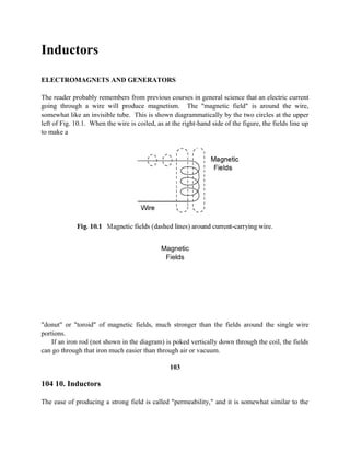
  • 1. Inductors ELECTROMAGNETS AND GENERATORS The reader probably remembers from previous courses in general science that an electric current going through a wire will produce magnetism. The "magnetic field" is around the wire, somewhat like an invisible tube. This is shown diagrammatically by the two circles at the upper left of Fig. 10.1. When the wire is coiled, as at the right-hand side of the figure, the fields line up to make a Magnetic Fields "donut" or "toroid" of magnetic fields, much stronger than the fields around the single wire portions. If an iron rod (not shown in the diagram) is poked vertically down through the coil, the fields can go through that iron much easier than through air or vacuum. 103 104 10. Inductors The ease of producing a strong field is called "permeability," and it is somewhat similar to the
  • 2. "dielectric constant" described on page 92. Iron is easily "polarized" magnetically, because it has many "unpaired" electrons that are spinning. An electron spinning generates a small magnetic field of its own. The spins can be lined up in the same direction, if they are put in a field such as the one from the wire. In some ways this is similar to the charges lining up inside the ceramic "dielectric" shown on page 91, thus raising the capacitance. Of course, an iron core plus a coil of wire can be an "electromagnet." When the current is first turned on, the field suddenly expands, from zero to whatever the final size will be at the maximum current. The reader probably remembers, also, that if a second wire is moved through a stationary magnetic field, or if the field is moved across a stationary wire, either way, a new voltage will be generated in that second wire. This is the principle of the "electric generator," which is used to make most of the electricity that comes to our houses and factories. A convenient concept is that "lines of magnetic field are being cut by the wire." (The field really varies smoothly with distance, and it is not grainy like wood. But for convenience we imagine lines, where the more lines, the stronger the field.) A higher voltage will be generated if more of these conceptual "lines" are being cut per second. If there are two coils, both stationary, as in Fig. 10.2, and an electric current is suddenly turned on in the left-hand coil, the magnetic field lines will quickly expand from zero to the final size, and they will get "cut" very fast by the stationary wires of the right-hand coil. Thus a high voltage will be generated in that coil. If the current in the left-hand ("primary") coil is turned off suddenly, the field lines will be cut as they collapse back to zero size, but in the opposite direction. The voltage in the right-hand "secondary" coil will be generated with opposite polarity. (It could be a high voltage, if the turn- off is fast enough.) If alternating current is put through the primary, then ac voltage will appear in the secondary, and this of course is a typical use of the "transformer." 10. Inductors 105 If there are more turns in the secondary coil, each turn is a little voltage generator in series with the others, so a higher voltage will appear across the terminals of the secondary. However, the amount of power coming out must be the same as what goes in, because power is energy per time (see the bottom of page 16), and energy can not be made or destroyed — it can only be changed in its form. Since power is voltage times current (eqn. 2.8 on page 17), if there is a higher voltage in the secondary than in the primary, then there must be a lower current, in order
  • 3. for the energy per second to be constant. These are in direct proportion to the ratio of turns, primary versus secondary. On the other hand, if there are fewer turns in the secondary than in the primary, then there will be a lower voltage. However, more current could then be gotten from the secondary, again depending on the ratio of turns. This is analogous to a mechanical lever, where higher speed can only be at lower force. EXPERIMENTS Transformers Ordinarily, the primary coil of the transformer used in this course would be plugged into a 120 V ac wall socket, and only 12 volts of ac would be available in the secondary, because that has ten times fewer turns than the primary has. Thus, this transformer is usually in a "step-down" mode, and in fact it was used that way in the optional experiment on page 98 of the previous chapter. If the circuit of Fig. 10.2 on the previous page is assembled with the 9 volts going into the primary (two heavily insulated black wires), it will still be used in the "step-down" mode, and the neon bulb will not light when hooked up to the secondary (lightly insulated yellow wires), because it requires much more than 9 volts, and instead it will probably be getting less. (Actually, it could be lit if the battery was connected or disconnected fast enough to make up for the unfavorable ratio of turns, but probably neither operation can be done fast enough here.) The neon bulb will flash brightly if the battery is connected to the original secondary (yellow-insulated wires of the transformer) and then suddenly disconnected, and the bulb is attached to the original primary (thicker wires with black insulation), because everything is favorable for a high voltage output— the step-up, and a fast current decrease in the primary. There will be less current out, but it only takes a very low current to operate the neon bulb, as was seen on page 6 of Chapter 1. (Note that the ignition coil in an automobile works this way, but with far more turns in the secondary. With not so many turns, it is used in "switching power supplies," including "inverters" that change dc to ac.) 106 10. Inductors Autotransformers and Inductors Figure 10.3 shows only the 12 volt side of the transformer being used, and the 9 V dc is going to one end (yellow) plus the "center tap" (thin black insulation). The experimenter should attach the oscilloscope with the vertical being voltage (CH2/Y), versus the horizontal being time (TIME/DIV = 0.1 s) hookup. The input MODE is CH2, the trigger MODE is AUTO, and the TRIGGER SOURCE is VERT (similar to pages 76 and 77). The VOLTS/DIV can start out at about 1 but be changed as needed, including rotating the central VARIABLE knob.
  • 4. As usual in this course, there is no real switch, and a clip lead is simply touched for a short time ("momentarily") to a wire or terminal, to put a short burst of current through half of the "12 volt" coil (ordinarily the secondary, but acting as a primary here). When the current is suddenly increased, a downward spike appears on the scope, showing that the "top" half of the center- tapped coil has 10. Inductors 107 negative voltage going to the scope hook, and positive going to its grounded clip lead. This is just the opposite of the voltages on the "bottom" half of the coil. Therefore the two halves tend to cancel each other, whenever we try to suddenly increase the current, which tends to prevent the current from increasing quickly. The next step is to suddenly "open" the "switch," and an upward spike appears, meaning that a voltage has been generated in the top half-coil that adds to the bottom half's voltage. The overall action therefore tends to prevent the current from stopping quickly. COMMENT Several things can go wrong with this experiment, although it should be possible to make it produce the exact result described above. First of all, the experimenter might verify that an
  • 5. "upward" spike on the scope display does indeed mean a positive voltage on the BNC cable's hook. (Be sure that the NORM / INV button has not been pushed accidentally.) This can be checked by attaching the hook and ground clip directly to the battery, with nothing else attached, and seeing whether the bright spot in the display goes upward. (In fact, the experimenter should get in the habit of "checking out" the scope like this, whenever results do not match expectations.) Secondly, sometimes a capacitance inside the scope gets charged up and then will not respond for a second trial. If that seems to be the case, discharge it before each new trial, by momentarily touching the hook to the ground clip. Thirdly, sometimes safety devices inside the scope prevent spikes of certain polarities. If the downward spike appears but the upward one will not, try reversing the polarity of the battery, and also pushing the NORM / INV button. Then both spikes should become visible, in this doubly inverted mode. Another point is that very little current flows into the scope, because of its extremely high "input impedance." If a low resistance such as an ammeter is attached to the top half-coil, then considerable current will flow, and this will make its own magnetic field, which interacts with the field of the bottom half-coil in a complex manner. The voltages of the two halves might then become additive and not cancel. The action of the top and bottom halves of the coil is similar to the action of the primary and secondary of an ordinary transformer, except that in the above experiment they are parts of the same coil, and they have the same numbers of turns. In some cases it is desirable to use just one continuous coil with a "tap," but not necessarily at the center, and in fact it can be movable, to provide varying voltages. This is called an "autotransformer," and it is often used to convert 120 volts to either lower or higher voltages, all ac, for operating small heaters or 108 10. Inductors stirring motors in chemical laboratories. The brand name of one such commonly used device is Variac® . LESSON The main idea of this experiment is that a fast-changing current in a coil will "induce" an opposite voltage in a nearby coil, and also in itself. The latter effect is what causes an inductor to resist change in the current going through it, which produces the electrical analog of mechanical inertia, including the "inductive kick" seen in Chapter 1. It does not have to be center-tapped at all, and in fact it usually is not. When the current changes fast, every turn of a coil induces an opposing voltage in each other turn, and this causes "inductance." By comparison, direct current goes through an inductor with no more resistance than it would have in a straight wire with no metal core — in other words, easily. But the higher the frequency (faster change in direction), the less current gets through an inductive coil, especially if it has an iron core to enhance the magnetic action. A mechanical analog of an inductor is shown in Fig. 10.4. As briefly mentioned on the very first page of Chapter 1, an inductor acts like a heavy piston inside a water pipe, tending to
  • 6. prevent fast changes in flow, either increases or decreases. There is very little resistance to steady water flow, similar to dc electricity in an inductor. On the other hand, high speed changes in direction would meet great resistance, similar to high frequency ac in the same inductor. Pipe Fig. 10.4 A piston analog of an inductor, with an O-ring seal at each end. Shorted Additional Coil The experimenter should construct the circuit of Fig. 10.5 on the next page. At first, the wires shown as dashed lines are not connected. The experiment is done as on page 7 of the first chapter, where the "switch" is opened suddenly, and there is a bright flash in the neon bulb. Then the short circuiting clip lead (dashed line in the diagram) is attached to the transformer's 120 volt coil (heavily insulated black wires or soldered-on power cord). Now when the switch is opened, there is no neon flash. What is happening is that current is induced in the "shorted" coil, as the battery current suddenly decreases. This new current has a magnetic field 10. Inductors 109 that tends to stop the current faster, whenever the battery current decreases. That of course is the opposite of tending to keep it going, as the coil turns on the other side of the transformer do to each other. 9 Volts
  • 7. There is a very important consequence of this behavior. First of all, if there is no short circuit, then the left side has a high inductance, which resists the flow of ac current. (Of course, we are not using true 60 Hz ac here, but transformers usually do.) Therefore, when there is no output (no "short" on the right-hand side, as shown here), very little current flows into the input, and the system is just "idling." A transformer can be plugged into a source of ac and hardly draw any power under such conditions, while it is waiting to be used. When a "load" (such as an electric motor) is later attached to the output side, current flows through both sides, and of course power is then being drawn from the source, possibly a wall socket. It is only drawn from the input side as it is used at the output side, so it does not waste power if it is not being used. 110 10. Inductors If there is an extreme case such as a short circuit in the output, as we intentionally produced here in order to make the effects easy to observe, then there will also be a short circuit at the input. This could burn out either side. Something similar happens with an electric motor (Fig. 20.1 on page 215), which can spin at high efficiency if it is not being used, but which draws far more current if it is slowed down by heavy use. It will become a short circuit and burn out, just like the input side here, if an
  • 8. excessive mechanical load completely prevents rotation. The reason, briefly, is that a motor rotating fast has high frequency ac going through its inductors, and the inductors (various coils) inside the motor tend to prevent the current from changing direction so fast. Therefore, very little ac current flows. When the motor slows down, the frequency (speed of direction change) slows, and more current can get through. If the motor stops, it is like dc going through its internal inductors, and too much current flows. This will be explained further in the chapter on motors. Snubbers Disconnecting the short circuit wire, and then opening the switch again will make a spark and also a neon flash at the "switch" itself. This spark is very hot and can do a lot of damage to whatever real switch (as contrasted to our make-believe "switch") is actually used to turn off a large transformer or motor or other inductor. In order to prevent the spark, a "snubber" can be used (sometimes called a "spark suppressor" or "spike suppressor"). Attaching a clip lead where the upper-left dashed line is shown in Fig. 10.5, and thus putting the capacitor and resistor across the "switch," the capacitor will absorb the inductive kick and prevent the high voltage spark. The inductive current will still flow for a short time after the switch is opened suddenly, but it goes into the capacitor instead of making a spark. There is no longer enough high voltage to light the neon bulb, which further proves that the snubber is doing its job. The 100 ohms is high enough to prevent excessive initial current from damaging the capacitor, but low enough to soak up the inductive kick. If the capacitor is used many times in a row, it will eventually charge up and then fail to work for snubbing the sparks. In that case, a 1,000 ohm resistor should be put across the capacitor to slowly discharge it. (In most real equipment, the capacitors are only about 100 microfarads (mfd), and they have a resistor for discharging.) There are other types of spark snubbers, which will be explained in the chapter on diodes. 10. Inductors 111 Symbols Another way to draw coils is shown in Fig. 10.6. It is often used in modern publications, because it is easier to draw than complete spirals. The two black dots on the left-hand transformer indicate that, at a certain time, the current is coming "upwards," out of both sides. Since alternating current goes both "up" (as shown here), and also "down" a fraction of a second later, it is pointless to say "+" or "-" and, instead, we describe the left-hand transformer as "being in phase." In the right-hand transformer, the two coils are wound differently from each other, so at any time when "positive" current is going "up" in the primary coil, it is going "down" in the secondary. We describe this as "being 180 degrees out of phase." (The reader might refer to Fig. 10.8 for further clarification.) The black dots are only shown in those cases where this is an important item. In Phase 180 Degrees Out of Phase
  • 9. Voltage Versus Current While the oscilloscope is still hooked up, the experimenter can change the circuitry to that of Fig. 10.7 (on the next page), which is the same as on page 97, except for the transformer primary being substituted instead of the capacitor. The 120 volt coil of the transformer can be used here, either with or without its long power cord. On the scope screen, the voltage (vertical) will be observed to increase before the current (horizontal) increases. The VOLTS/DIV knobs may have to be set for more sensitivity (lower voltages per display division), because even the multi-turn 120 volt winding will not have as much inductive effect as the 1,000 mfd capacitor had capacitance effect. In this case, the voltage can be applied to the coil immediately, but the current can not increase so fast, just like water pressure on a heavy piston can not get it up to full speed instantly. An increase in current induces a high reverse voltage, so the initial current increase is retarded in its timing. 112 10. Inductors 9 Volts Fig. 10.7
  • 10. Phase As observed in the curve tracer experiment, the current lags the voltage, and the voltage is said to lead the current, when an ac sine wave goes through an inductor. (Doing the experiment requires two transformers, so it will not be performed here.) The relationship is shown in Fig. 10.8. Actually, the pendulum on page 98 Fig. 10.8 Sine wave ac in an inductor, showing lead and lag. 10. Inductors 113 is more closely analogous to the inductors in this chapter than to the capacitors in the previous chapter, but the general ideas of instantaneous ("leading") versus cumulative ("lagging") behavior apply to both. OPTIONAL Current Versus Time
  • 11. When the voltage is first applied, and the current builds up, that current follows the following equation: I = Imax ( 1 -e-t/τ ) (10.1) where t is time and τ is the time constant, "tau" (the time when the current gets to about 2/3 of its maximum value). This is similar to the capacitor example on page 94, but with current changing now instead of voltage. The curves also are similar, but with inductor current substituted for capacitor voltage. The voltage itself is given by Ohm's law, V = IR. (For "e," see page 95.) When the driving voltage is removed, the current decays according to: I = Imax ( e-t/τ ) (10.2) where τ is the time at which the current gets to about 1/3 of Imax . Although τ = RC with capacitors (page 95), τ = L/R with inductors, where L is the inductance. Thus a resistance tends to decrease the time constant with inductors, while it increases it with capacitors. The inductive kick, that is, the voltage generated by decreasing the current quickly, is V = L[(current change) / (time change)]. Thus, the faster the change in current, the higher the voltage that is generated, almost without limit. Reactance There is an inductive reactance, similar to the capacitive reactance described on page 99. The formula is XL = 2π fL (10.3) where f is the frequency, and L is the inductance. The unit of frequency, f, is the Hertz, named after the early scientist, Heinrich Hertz, and the unit of inductance, L, is the Henry, named after the early scientist, Joseph Henry. The vector diagram on page 101 can still be used to show the relationship between inductive reactance, XL, and resistance, R, with the hypotenuse being the impedance, Z. Similarly, the "loss" is the tangent of the angle, delta. The power factor for inductors is also R / Z, as on page 101. 114 10. Inductors Inductance The value of the inductance, in units of microhenrys, can be calculated approximately from the dimensions of the coil shown in Fig. 10.9, as follows: µ (turns)2 (radius)2 L = (10.4) 9 (radius) + 10 (length) where the radius and length are in inches. The Greek letter µ ("mu," pronounced "myoo") is the
  • 12. relative permeability, compared to the permeability of vacuum. This would be essentially the µ of the iron (or "ferrite" ceramic) core. (The µ of air is close to that of vacuum and is ignored in air-core coils. See also page 268.) The symbol at the left, the circle with a sine wave inside, stands for any source of Radius Length alternating voltage or current, such as the output of a transformer or generator or oscillator. (The latter will be covered in a later chapter.) The center-tap has no effect on the inductance, if it is not attached to anything. COMMENT Inductors tend to be bulky and heavy, and in many cases they can be replaced by smaller, lighter weight capacitors (as will be described later, on page 123). That is why, instead of inductors, circuit designers try to use capacitors or "gyrators" (to be mentioned briefly on page 125). 10. Inductors 115 LOSSLESS CONTROL
  • 13. Inductors decrease ac current by "reactance," similar to the way capacitors do (see last text paragraph on page 102). If the inductor were perfect, and had no resistance, then no power would be lost through heating ("dissipation"). Nearly perfect inductors are nearly lossless. For this reason, the autotransformer described at the bottom of page 107 can decrease ac voltage and current with very little wasted power. Also, a simple two-terminal "ballast" inductor, which is not center-tapped, is often used to limit the current in fluorescent lights. Another way to do this, as also mentioned on page 102, is by fast on-off switching. This is done with SCR controllers, as will be described Chapter 21. If a large rheostat is used, however, a great deal of power is wasted in the form of heat dissipation. That method was used in old electrical equipment such as early electric railroad engines and trolley cars, before it was realized that inductors could be used and even earlier, when most electric power was dc. SATURABLE CORES AND MAG-AMPS As the alternating current input of a transformer increases, the output also increases, but it reaches a maximum value when the core becomes "saturated" and can no longer increase its magnetization. If the transformer is purposely operated under these conditions, the output will be constant, even if the input varies a small amount. This is sometimes used to provide a dependable, constant voltage to operate sensitive instruments, heaters, and other devices, and it is called a "saturable core reactor" or a "constant voltage transformer." In newer equipment designs, it has mostly been replaced by the semiconductor devices that will be described in Chapter 15 (Fig. 15.6). If a transformer is operated a little bit below saturation, and a small direct current is sent to a third coil, this can be used to sharply change the output, by pushing the total magnetization up into saturation. (None of the dc itself becomes part of the output — it only affects the ac, but it is not part of it.) Then, by decreasing the dc a small amount, the iron core can become unsaturated, and far more ac will go through, into the output. Thus a small dc signal can control a large ac "throughput." This is called a "magnetic amplifier," or "mag-amp." It is used to control high currents for heaters in older industrial furnaces, although SCRs are used instead, for modern designs. The SCR and similar devices will be described in Chapter 21. 116 10. Inductors EQUIPMENT NOTES Components For Radio Shack This Chapter Catalog Number Battery, nine volts 23-653 Clip leads, 14 inch, one set. 278-1156C Transformer, 120V to 12V, 450 ma, center tapped 273-1365A Resistor, 100 ohm, 10 or
  • 14. 1 watt 271-135 or 271-152A Potentiometer, 5K 271-1714 or 271-1720 Capacitor, 1000 mfd 272-1019 or 272-1032 Neon test light, 90 volts 22-102 or 272-707 Oscilloscope, Model OS-5020, LG Precision Co., Ltd., of Seoul, Korea