3. Equivalent circuit
• The equivalent circuit comprised of two
resistors, one fixed (RB2) and one variable
(RB1) and a single diode (D).
• RB1 varies with IE.
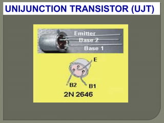
UNIJUNCTION TRANSISTOR (UJT)
5. Equivalent circuit
• RBB is the interbase resistance when IE =
0 i.e.
021
EIBBBB RRR
• Typical range of RBB : 4 k - 10 k
• The position of the aluminum rod
determine the relative values of RB1 and
RB2.
UNIJUNCTION TRANSISTOR (UJT)
11. Programmable unijunction Transistor (PUT)
Although it has the same name as a UJT the programmable
unijunction transistor’s structure is not the same. It is
actually more similar to an SCR.
12. Programmable unijunction Transistor
The PUT can be “programmed” to turn on at a certain voltage
by an external voltage divider. This yields a curve similar to a
UJT.
13. Programmable unijunction Transistor (PUT)
External PUT resistors R1 and R2 replace unijunction
transistor internal resistors RB1 and RB2, respectively. These
resistors allow the calculation of the intrinsic standoff ratio η.
14. Programmable unijunction Transistor (PUT)
VR is voltage divider (R1 and R2 can be specified)
Vc capacitor voltage
When Vc > VR the PUT will conduct
16. UJT RELAXATION OSCILLATORS
Assume that the initial
capacitor voltage, VC
is zero. When the
supply voltage VBB is
first applied, the UJT
is in the OFF state. IE
is zero and C charges
exponentially through
R1 towards VBB.
The operation
17. UJT RELAXATION OSCILLATORS
When the supply
voltage VC (= VE)
reaches the firing
potential, VP, the UJT
fires and C discharges
exponentially through
R2 until VE reaches
the valley potential
VV.
18. UJT RELAXATION OSCILLATORS
When VE reaches the valley potential VV the
UJT turns OFF, IE goes to zero and the
capacitor is recharged.
This process repeats itself to produce the
waveforms for vC and vR2 as shown below;
22. UJT RELAXATION OSCILLATORS
Condition for switching-ON
To switch-on a UJT,
the emitter current IE
must be able to reach
the peak current IP
i.e.
11 RIV PIIR
PE
24. UJT RELAXATION OSCILLATORS
In other words, R1 must
be small enough such
that IE is not limited to a
value less than IP when
VC = VP.
Condition for switching-ON
26. UJT RELAXATION OSCILLATORS
Condition for switching-OFF
To switch-off a UJT,
the emitter current IE
must drop below IV
when VC = VV.
Hence;
VVBB VRIV 1
30. UJT RELAXATION OSCILLATORS
It can be shown that;
PBB
VBB
VV
VV
CRt ln11
and;
V
P
B
V
V
CRRt ln212
31. UJT RELAXATION OSCILLATORS
The periodic time;
21 ttT
In many cases, t1 >> t2, therefore;
PBB
VBB
VV
VV
CRtT ln11
32. UJT RELAXATION OSCILLATORS
When VBB and VP are much greater than VV,
then;
PBB
BB
VV
V
CRT ln1
And if VBB >> Vpn i.e. VP VBB, then
BBBB
BB
VV
V
CRT
ln1
Rangkaian ekivalen terdiri dari dua resistor, satu tetap (RB2) dan satu variabel (RB1) dan dioda tunggal (D).
RB1 bervariasi dengan IE.
Variasi RB1: 5 k sampai 50 untuk variasi sesuai 0 A sampai 50 A di IE.
RBB adalah resistansi interbase ketika IE = 0 yaitu
Berbagai Khas RBB: 4 k - 10 k Posisi batang aluminium menentukan nilai relatif RB1 dan RB2.
Untuk VE> VRB1 oleh VD (0,35 0,70 V),
dioda akan aktif dan IE akan mulai mengalir melalui RB1
VD=ideal dioda
Peak point=titik puncak
Valley point = titik lembah
Meskipun memiliki nama yang sama dengan UJT struktur yang diprogram unijunction transistor adalah tidak sama. Hal ini sebenarnya lebih mirip dengan SCR.
PUT dapat "diprogram" untuk mengaktifkan pada tegangan tertentu oleh pembagi tegangan eksternal. Ini menghasilkan kurva yang mirip dengan sebuah UJT.
Resistor PUT eksternal R1 dan R2 menggantikan unijunction transistor resistor internal yang RB1 dan RB2, masing-masing. Resistor ini memungkinkan perhitungan intrinsik kebuntuan rasio η.
Vak>vp …on
Vak<vp…. off
VR adalah pembagi tegangan (R1 dan R2 dapat ditentukan) Vc tegangan kapasitor Ketika Vc> VR PUT akan on
Asumsikan bahwa tegangan kapasitor awal, VC adalah nol. Ketika suplai tegangan VBB pertama diterapkan, UJT dalam keadaan OFF. IE adalah nol dan C di isi secara eksponensial melalui R1 menuju VBB.
Ketika tegangan suplai VC (= VE) mencapai potensi , VP, hidup UJT dan C pembuangan secara eksponensial melalui R2 sampai VE mencapai lembah (titik rendah) potensial VV.
Ketika VE mencapai valley potensial VV yang UJT ternyata OFF, IE menjadi ke nol dan kapasitor diisi. Proses ini berulang untuk menghasilkan bentuk gelombang untuk vC dan VR2 seperti yang ditunjukkan di bawah ini;...
Peak point=titik puncak
Valley point = titik lembah
Untuk beralih-on UJT , emitor IE saat ini harus mampu mencapai IP saat puncak yaitu
Dengan kata lain, R1 harus cukup kecil sehingga IE tidak terbatas pada nilai kurang dari IP ketika VC = VP
Mengaktifkan UJT
Untuk beralih-off UJT a, emitor IE saat ini harus turun di bawah IV ketika VC = VV. Oleh karena itu;
Dengan demikian, untuk fire UJT tersebut
Dengan demikian, untuk menjamin beralih ON dan OFF, kondisi berikut harus dipenuhi;