SlideShare ist ein Scribd-Unternehmen logo
1 von 13
Downloaden Sie, um offline zu lesen
Natural Gas Processing with Membranes: An Overview
                  Richard W. Baker and Kaaeid Lokhandwala*
                  Membrane Technology and Research, Inc., 1360 Willow Road, Suite 103, Menlo Park, California 94025


                  Every year, the world uses close to 100 trillion scf (standard cubic feet) of natural gas. All of this gas requires
                  treatment before it enters the pipeline, making natural gas processing by far the largest market for industrial
                  gas separation processes and equipment. Of this huge market, membranes have less than a 5% share, but this
                  is changing; membrane-based removal of natural gas contaminants is growing faster than any other segment
                  of the membrane gas separation business. This paper gives an overview of the membrane technology in
                  current use for natural gas treatment and outlines the future prospects.

1. Introduction                                                        Table 1. Composition Specifications for Natural Gas Delivery to the
                                                                       U.S. National Pipeline Grid1
   Raw natural gas varies substantially in composition from                                                Range in U.S. Well Compositions
source to source. Methane is always the major component,
                                                                                                            % of total      component
typically 75%-90% of the total, but natural gas also contains            component        specification      U.S. gas          content
significant amounts of ethane, some propane and butane, and
1%-3% of other higher hydrocarbons. In addition, the gas                               <2%                 72%           <1%
                                                                                                           18%           1-3%
contains undesirable impurities, such as water, carbon dioxide,        CO2
                                                                                                           7%            3-10%
nitrogen, and hydrogen sulfide. Although the composition of                                                3%            >10%
raw gas varies widely, the composition of gas delivered to             total                               100%
commercial pipeline grids is tightly controlled. Typical U.S.          water           <120 ppm                          800-1200 ppm
natural gas pipeline specifications are shown in Table 1.                              <4 ppm              76%           <4 ppm
   To meet pipeline specifications, all natural gas requires some      H2S
                                                                                                           11%           4-1000 ppm
treatment (if only to remove water), and ∼20% requires                                                     4%            1000-10000 ppm
                                                                                                           8%            >10000 ppm
extensive treatment, before delivery to the pipeline.1 The
                                                                       total                               100%
opportunity for membranes lies in processing raw gas to meet
                                                                       C3+ content     950-1050 Btu/scf;
these specifications.
                                                                                         dew point:
   Processing of natural gas is, by far, the largest industrial gas                      < -20 °C
separation application. The U.S. consumption of natural gas is         total inert gases <4%               14%           >4%
∼22 trillion scf/yr; total worldwide consumption is ∼95 trillion          (N2, He)
scf/yr. (Throughout this paper, “scf” is used to represent standard
cubic feet.) This consumption drives a worldwide market for            pressure overhead gas. The regenerated absorbent liquid is then
new natural gas separation equipment of ∼$5 billion per year.          recycled to the first tower. Heat exchangers are used to minimize
Currently, membrane processes have <5% of this market, almost          the cost of heating the absorber fluid.
all of which is applied toward the removal of carbon dioxide.             Absorber-stripper units represent a proven, well-accepted
   The principal current suppliers of membrane natural gas             technology in the gas processing industry, and no gas processing
separation systems are listed in Table 2.                              plant designer will be fired for recommending the installation
   Membrane technology competes most directly against absorp-          of one of these units. Having said this, the high-pressure
tion for carbon dioxide removal.2 A typical absorption process         absorber tower in particular is an expensive, large, thick-walled,
is illustrated in Figure 1. Two towers are used. In the first tower,   heavy vessel. The size of such a tower is proportional to the
the feed gas, usually at high pressure, and an absorbent liquid        mass of the material to be absorped. In natural gas dehydration,
flow countercurrent to each other. The absorbent liquid that           only a few hundred parts per million (abbreviated hereafter as
contains the absorbed component (carbon dioxide, water, or             ppm) of water must be removed; consequently, these systems
heavy hydrocarbon) is removed from the bottom of the tower.            are relatively compact and low in cost. On the other hand, the
The liquid is then heated and sent to a low-pressure stripper          removal of carbon dioxide from natural gas may require 10%-
tower. The combination of heat and lower pressure liberates            20% of the gas to be removed, which means large amounts of
the sorbed component, which leaves the stripper tower as a low-        absorbent fluid must be used in large towers. Carbon dioxide
                                                                       absorber-strippers are also relatively high-maintenance units.
  * To whom correspondence should be addressed. E-mail address:        The need to heat and cool the recirculating fluids requires
kaaeid@mtrinc.com.                                                     careful, well-monitored operating procedures. Furthermore,
Figure 1. Typical natural gas absorber-stripper treatment process using
amine absorbents to remove carbon dioxide. Similar processes use trieth-
ylene glycol for water removal and lean oil for heavy hydrocarbon removal.

corrosion is a critical maintenance issue. Amines are the most
common sorbents for carbon dioxide, and the degradation of
amines leads to corrosive mixtures that can destroy the system
within a few days if left unchecked. Constant monitoring of
the amine absorbent chemistry is needed. The need for regular
maintenance and good operator care hinders the use of amine                  Figure 2. Structure of membranes used in membrane gas separation
absorber-strippers in remote locations.                                      processes: (a) anisotropic Loeb-Sourirajan membranes and (b) composite
                                                                             membranes.
   Membrane companies first broke into the natural gas process-
ing industry in the 1980s, offering systems for carbon dioxide
removal in competition with amine absorption. Membranes                      collect on the membrane surface. In addition, the gas is typically
could gain a foothold in locations where the operational issues              treated at relatively high pressures of 30-60 bar. Under these
previously mentioned are especially problematic. The first                   conditions, the generally higher permeances of flat sheet
membrane systems to separate carbon dioxide from natural gas                 membranes formed as spiral-wound modules can compensate
were introduced by Grace Membrane Systems (a division of                     for their higher cost (on a $/(m2 membrane) basis), compared
W.R. Grace), Separex (now part of UOP), and Cynara (now                      to hollow-fiber modules. Currently, both types of membrane
part of Natco). These companies used anisotropic cellulose                   modules (spiral and hollow-fiber) are produced, by different
acetate membrane that was produced using the Loeb-Sourirajan                 companies, and no clear winner has emerged.
technique.3-5 Cellulose acetate membranes are still widely used.                One trend that has emerged in commercial gas separation
In the last 10 years, they have begun to be challenged by newer              membranes is a move to composite membranes, in which a base
membranes, such as the polyimide membranes (made by Medal                    anisotropic membrane is used as a highly porous support (to
a division of Air Liquide)6 and perfluoropolymer membranes                   provide the mechanical strength required), and a thin layer of
(made by ABB/MTR).7-9                                                        permselective material (typically 0.2-1.0 µm thick) is deposited
   1.1. Membrane Production Trends Making Membrane                           onto the support to perform the separation. Hollow-fiber
Separations More Competitive. Current membranes used for                     membranes and flat sheet membranes can be made in this
natural gas separation applications are produced as hollow fibers            composite membrane form. Composite membranes, as shown
or flat sheets packaged as spiral-wound modules. Hollow-fiber                in Figure 2b, offer two key advantages over the conventional
modules allow large areas of membrane to be packaged into                    Loeb-Sourirajan anisotropic membrane (shown in Figure 2a).
compact membrane modules. This advantage proved decisive                     In Loeb-Sourirajan membranes, the porous support layer that
in the choice of membranes for the separation of nitrogen from               provides mechanical strength and the relatively dense surface
air, which was an early large-scale membrane gas separation                  layer that performs the separation are formed at the same time
process. Nitrogen production from air uses relatively low-                   from the same material. This limits the number of materials
permeability membrane materials to process a clean, non-                     that can be used to make the membrane. It also means the
plasticizing gas (air) at low pressures (generally <10 bar).                 separation properties are often compromised to make membranes
Essentially all membrane nitrogen-from-air separation systems                with sufficient mechanical strength.
use hollow-fiber modules. Natural gas streams, in contrast,                     Composite membranes consist of a microporous support layer
contain multiple components, some of which (water, carbon                    coated with one or more thin layers of a different polymer that
dioxide, C4+ hydrocarbons, aromatics) degrade and plasticize                 performs the separation. Because the separation function and
the membrane. Natural gas streams may also contain entrained                 the mechanical support function are separated, each can be
oil mist, fine particles, and hydrocarbon vapors that can easily             optimized separately, and the polymer best suited for each

Table 2. Principal Suppliers of Membrane Natural Gas Separation Systems
           company                    principal natural gas separation       membrane module type                    membrane material
    Medal (Air Liquide)                 CO2                                      hollow fiber                polyimide
    W.R. Grace                          CO2                                      spiral-wound                cellulose acetate
    Separex (UOP)                       CO2                                      spiral-wound                cellulose acetate
    Cynara (Natco)                      CO2                                      hollow fiber                cellulose acetate
    ABB/MTR                             CO2, N2, C3+ hydrocarbons                spiral-wound                perfluoro polymers silicone rubber
    Permea (Air Products)               Water                                    hollow fiber                polysulfone
Table 3. Typical Costs for Membranes, Membranes in
8-In.-Diameter Spiral-Wound Modules, and Module Skidsa
                                  Typical Cost ($/m2 of membrane)
                                gas separation       reverse osmosis
                                 (steel vessels    (fiberglass vessels,
        type of unit           and components)     plastic components)
membrane                              20                   5
membrane in spiral-wound             100                 10-15
  module form
membrane modules in a skid           500                 30-50
  a Hollow-fiber reverse osmosis skids are normally less expensive on a
per-square-meter-of-membrane basis; however, lower permeances offset
much of this advantage.

function can be used. Composite membranes allow high-cost
polymer materials to be used economically in the separating
layers. Tailor-made polymers with good separating properties
often cost as much as $1000/kg-$10000/kg to synthesize. A
Loeb-Sourirajan membrane generally uses ∼50 g of polymer/
(m2 membrane), so the material cost of membrane made from
these high-cost polymers is in the $50/m2-500/m2 range.
Composite membranes generally use a dense layer of polymer
only 0.2-0.5 µm thick, so less than one gram of polymer/m2
of the high performance material is needed for a comparable               Figure 3. Photograph showing the development of hollow-fiber membrane
separation. The cost of this polymer is much more affordable,             modules at Cynara, from the first 5-in. modules of the 1980s to the 30-in.
at $1/m2-10/m2. The microporous support membrane for most                 diameter behemoths currently being introduced.10 Photo courtesy of Cynara
                                                                          Company (now part of NATCO Group, Inc.).
natural gas applications can be made from conventional low-
cost materials.
                                                                            Gas transport through dense polymer membranes is governed
   A second emerging trend in commercial membrane separa-
                                                                          by the expression
tions is a move to larger membrane modules. Natural gas
separations operate with high-pressure flammable gases that
                                                                                                          DiKi(pio - pil )
must be contained in code-stamped heavy steel vessels. The
                                                                                                   ji )                                         (1)
impact of the cost of these vessels, flanges, valves, and pipes                                                  l
on the system capital cost is illustrated in Table 3. Costs of
module skids purchased for ultrafiltration/reverse osmosis                where Jl is the volume (molar) flux (expressed in terms of cm3-
applications are lower by a factor of 5-10. This difference               (STP) of component i/(cm2 s)), l the membrane thickness, pl o
reflects the higher production volumes and lower costs of the             the partial pressure of component i on the feed side, and pi l
plastic components and fiberglass housings that can be used in            the partial pressure of component i on the permeate side. The
water treatment processes.                                                diffusion coefficient (Di) is an indication of the mobility of the
   Table 3 shows that the cost of membranes used in gas                   individual molecules in the membrane material, and the gas
separation processes is a small fraction of the final membrane            sorption coefficient (Ki, with units of cm3(STP) of component
skid cost. High skid costs arise because of the many pressure             i per cm3 of polymer per unit pressure) is an indication of the
vessels, pipes, flanges, and valves that are required. One way            number of molecules dissolved in the membrane material. The
to reduce membrane skid cost is to increase the permeance of              product DiKi can be written as Pi, which is called the membrane
the membranes, allowing a smaller membrane area to be used                permeability; this is a measure of the membrane’s ability to
to treat the same volume of gas. All membrane manufacturers               permeate gas.
pursue this approach. Increasing the feed gas pressure also                  The best measure of a membrane’s ability to separate two
reduces the membrane area required, and, hence, skid size, but            gases i and j is the ratio of their permeabilities, Ri/j; this
at the expense of larger compressors (higher capital cost) and            parameter is called the membrane selectivity, and it can be
increased energy consumption (higher operating cost). A third             written as
approach is to develop larger membrane modules and new skid
designs. Currently, most modules, both spiral-wound or hollow-                                              Pi [Di/Dj]
fiber, are designed to fit in 8-in.-diameter housings. However,                                    Ri/j )     )                                 (2)
                                                                                                            Pj [Ki/Kj]
12-in.-diameter spiral-wound modules are now being installed
in some units, and some hollow-fiber module producers are also
beginning to introduce very large modules, as shown in Figure             The ratio Di/Dj is the ratio of the diffusion coefficients of the
3.10 These developments, combined with the use of lower-cost              two gases and can be viewed as the mobility selectivity, which
module skids,11 are likely to significantly reduce the cost of            indicates the relative motion of individual molecules of the two
future membrane systems and increase their long-term com-                 components i and j. The mobility selectivity is proportional to
petitiveness.                                                             the ratio of the molecular size of the two permeants. The ratio
                                                                          Ki/Kj is the ratio of the sorption coefficients, which indicates
                                                                          the relative concentration of the components i and j in the
2. Permeation Theory
                                                                          membrane material. The sorption of a component increases with
   The factors that affect polymer membrane permeance and                 condensability of the component; therefore, the sorption selec-
selectivity have been discussed in detail in several review               tivity is proportional to the relative condensability of components
articles12-15 and will only be briefly reviewed here.                     i and j.
Table 4. Current Commercial Membrane Materials and Selectivities
                                                                             for Separation of Impurities from Natural Gas
                                                                                                                                                typical
                                                                                                     category of                             selectivities
                                                                                                      preferred                                  over
                                                                                 component            polymer              typical             methane
                                                                              to be permeated         material          polymer used             (%)a
                                                                             CO2                     glassy         cellulose acetate,         10-20
                                                                                                                        polyimide,
                                                                                                                        perfluoro polymer
                                                                             H2S                     rubbery        ether-amide block          20-30
                                                                                                                        co-polymer
                                                                             N2                      glassy         perfluoropolymer            2-3
Figure 4. Depiction showing the relative size (kinetic diameter) and                                 rubbery        silicone rubber               0.3
condensability (boiling point) of the principal components of natural gas.   water                   rubbery or     many                       >200
Glassy membranes generally separate using differences in size; rubbery                                  glassy
membranes separate using differences in condensability.                      C3+ hydrocarbons        rubbery        silicone rubber              5-20
                                                                                a   Selectivities are typical of those measured with high-pressure natural
   In polymer materials, diffusion coefficients decrease as the              gas.
molecular size increases, because large molecules interact with
more segments of the polymer chain than do small molecules.                  nitrogen. These membranes minimize size selectivity and
Hence, the mobility selectivity Di/Dj always favors the perme-               maximize sorption selectivity, and, therefore, they are methane-
ation of small molecules (such as water (kinetic diameter of                 permeable; but again, the selectivity is small. Finally, propane
2.65 Å) and carbon dioxide (kinetic diameter of 3.30 Å)) over                and other hydrocarbons, because of their condensability, are
larger ones (such as methane (kinetic diameter of 3.80 Å)).                  best-separated from methane with rubbery sorption-selective
   The sorption coefficient of gases in a polymer is a measure               membranes.
of the energy required for the gas to be sorbed by the polymer,                 Table 4 shows typical membrane materials and the selectivi-
and it generally increases as the condensability increases. Hence,           ties that can be obtained with good-quality membranes. These
the sorption selectivity Ki/Kj favors absorption of the more-                selectivities may seem low, compared to values commonly found
condensable gas. Methane (which has a boiling point of 113                   in the literature. This difference occurs because the literature
K) is less condensable than almost all of the other components               values are usually the ratios of the pure gas permeabilities.
in natural gas, so the sorption selectivity usually favors                   Selectivities measured with high-pressure gas mixtures, espe-
permeation of the nonmethane components.                                     cially natural gas mixtures that contain plasticizing components
   The sorption selectivity term Ki/Kj for a particular gas pair is          such as water, BTEX aromatics (benzene, toluene, ethylbenzene,
relatively constant for all amorphous polymers, but the mag-                 and xylene), and other heavy hydrocarbons are usually signifi-
nitude of the diffusion selectivity term Di/Dj is very dependent             cantly lower. The values given in Table 4 are selectivities that
on the nature of the polymer and, in particular, whether the                 might be reasonably expected by current commercial membranes
polymer is above or below its glass-transition temperature.                  operating on “real” gas streams.
Below the glass-transition temperature, the polymer chains are
essentially fixed; the polymer is a rigid, tough, glassy material            3. Applications
and the effect of differences in size of the permeating gases on
their relative mobility is large. If the polymer is above its glass             3.1. Carbon Dioxide Removal. Carbon dioxide is a common
transition temperature, motion of the polymer chains is possible.            contaminant of natural gas and must be removed to a level of
The polymer is then rubbery and elastic and the effect of                    <8% (usually <2%) to minimize corrosion of the pipeline. Until
molecular size of the permeating gases on relative mobility is               the introduction of membrane technology, the standard removal
reduced. In extreme cases, if the polymer is plasticized by a                technique was amine absorption.2 Amine absorption technology
low-molecular-weight component that facilitates motion of the                achieves almost complete removal of carbon dioxide. Generally,
polymer chains, the mobility selectivity term can be quite small,            ∼1% of the methane in the gas being treated is lost with the
and for similarly sized permeating molecules, the ratio Di/Dj                amine plant’s carbon dioxide vent gas stream, and another 1%-
can approach unity. It follows that changing the membrane                    4% of the methane is used as fuel to heat the reboiler of the
material chemistry to obtain the optimum mobility selectivity                amine stripper, so the total hydrocarbon losses are in the range
term is the most widely used method for tailoring membrane                   of 2%-5%. Early membrane plants had difficulty in meeting
materials and performance.                                                   this low hydrocarbon loss target. Better membranes and
   The molecular size and condensability of the principal                    improved process designs have since improved the competitive-
components in natural gas, relative to methane, are shown                    ness of membranes.
graphically in Figure 4. Water is small and condensable;                        The size of the absorbent recirculation rate, reboiler stripping
therefore, it is easily separated from methane by both rubbery               tower, pumps, and heat exchangers of an amine plant all increase
and glassy polymers. Rubbery and glassy polymers can also                    in proportion to the mass of carbon dioxide to be removed, and
separate carbon dioxide and hydrogen sulfide from natural gas.               they are relatively independent of the volume of gas to be
However, in practice, carbon dioxide is best separated by glassy             treated. Only the high-pressure absorption tower increases in
polymer membranes (maximizing size selectivity) whereas                      proportion to the volume of gas to be treated. Overall, this means
hydrogen sulfide, which is larger and more condensable than                  an amine plant that is designed to treat 20 million scfd (scfd )
carbon dioxide, is best-separated by rubbery polymer membranes               standard cubic feet per day) of gas that contains 5% carbon
(maximizing sorption selectivity). Nitrogen can be separated                 dioxide would be only slightly more costly than an amine plant
from methane by glassy polymers, but the difference in size is               designed to treat 5 million scfd of gas that contains 20% carbon
small, so the separations achieved are small. Alternatively,                 dioxide. Membrane plants, on the other hand, are able to treat
rubbery polymers can be used to permeate methane over                        high-concentration gas streams much more efficiently than low-
Figure 5. Typical membrane/amine hybrid plant for the treatment of
associated natural gas produced in carbon dioxide/enhanced oil projects; a
portion of the membrane plant’s permeate gas is usually used as a fuel for
the amine absorption plant.

concentration gas streams. A membrane plant designed to treat
5 million scfd of gas that contains 20% carbon dioxide would
be less than half the size of a membrane plant designed to treat
20 million scfd of gas that contains 5% carbon dioxide. It
follows that membrane plants are preferred for high-concentra-
tion gas streams and amine plants are preferred for relatively
low-concentration gas streams. Membrane plants, because of
their simple flow schemes, are also generally preferred when
processing small gas flows. Membrane plants processing <20
                                                                             Figure 6. Schematic plot illustrating the effect of gas flow rate and carbon
million scfd of gas are usually designed for unattended                      dioxide concentration in the gas on the choice of carbon dioxide removal
operation. Amine plants are more complex and require careful,                technology. This figure should be used with care, as site-specific issues
well-monitored operating procedures, so that unattended opera-               can produce very different results.
tion is generally less practical.
   In principle, the combination of membranes for bulk removal
of the carbon dioxide from natural gas with amine units as
polishing systems offers a low-cost alternative to all-amine or
all-membrane plants. However, this approach is limited to large
plants where the overall savings in capital cost are large enough
to offset the increased complexity of the plant, which now
contains two separation processes.10,16 Hybrid plants have also
been used in carbon dioxide flood-enhanced oil recovery projects
in which carbon dioxide is injected into an oil formation to
reduce the viscosity of the oil. Water, oil, and gas are removed
from the formation; the carbon dioxide is separated from the
gas produced and reinjected. Approximately 5% of U.S. oil is
produced this way.17 In these projects, the composition and
volume of the gas changes significantly over the lifetime of
the project. The modular nature of membrane units lends itself
to easy retrofitting of an existing amine plant, allowing the
performance of the plant to be adjusted to meet the changing
separation needs. Also, the capital cost of the separation system
can be spread more evenly over the project lifetime. A block
diagram of a membrane/amine plant is shown in Figure 5. In
this design, the membrane unit removes two-thirds of the carbon
dioxide, and the amine plant removes the remainder. A portion
of the permeate gas from the membrane unit is used as fuel for
the amine plant; the remainder is vented or reinjected. The
combined plant is significantly less expensive than an all-amine
or all-membrane plant.
   A schematic plot that illustrates the effect of gas flow rate
and carbon dioxide composition on the choice of separation                   Figure 7. Photographs showing CO2 membrane separation plants. Top
processes is shown in Figure 6. Similar figures with different               photograph shows a 9 million scfd membrane plant designed to bring 6%
numbers have appeared in the literature. Many site-specific                  CO2 gas to 2%; the plant is compact enough to be moved when the gas
issues can change these plots. Membrane systems, for example,                field is exhausted after a few years of operation (UOP/cellulose acetate
                                                                             membranes/spiral-wound modules; photo courtesy of UOP LLC). Bottom
are strongly favored in offshore platforms that produce an                   photograph shows the world’s largest membrane CO2 removal plant; this
increasing fraction of natural gas. An amine plant producer                  is a 500 million scfd unit that is designed to bring 5.7% CO2 gas to 2%
might draw a different figure. The range of size and complexity              (UOP/cellulose acetate membranes/spiral-wound modules).
of membrane carbon dioxide separating plants is illustrated in
Figure 7.                                                                    very limited number of membrane materials, of which cellulose
   3.1.1. Membranes Used. As shown previously in Table 4,                    acetate is probably the most common. This result surprises
current membrane carbon dioxide separation plants use a                      many researchers who point to literature data that show the
Figure 9. Graph showing that the difference between selectivities calculated
                                                                            from pure gas measurements and selectivities measured with gas mixtures
                                                                            can be large. The graph was constructed using data from Donohue et al.19
Figure 8. Robeson plot of CO2/CH4 selectivity versus membrane perme-        for carbon dioxide/methane with cellulose acetate films.
ability (permeance);18 the points shown are based on low-pressure pure-
gas measurements. For comparison, the performance of commercial             plasticizes the membrane, increasing the methane permeability
membranes when used to separate carbon dioxide from high-pressure natural
gas is shown on the same figure.                                            far above its pure-gas value.
                                                                               The mixed-gas data shown in Figure 9 are limited to simple
availability of much-better membrane materials. A widely                    CO2/CH4 mixtures; however, natural gas also contains water,
used method of comparing the performance of various mem-                    and 1%-5% heavy hydrocarbons. These hydrocarbons are also
brane materials is the selectivity/permeance plot popularized               absorbed by the membrane and often have as large a plasticiza-
by Robeson and shown in Figure 8.18 This plot shows the                     tion effect on membrane permeances as carbon dioxide. The
selectivity for CO2/CH4 obtained from the ratio of pure-gas                 BTEX aromatics present in most natural gas at concentrations
                                                                            of 200-1000 ppm are particularly troublesome. At this con-
permeabilities plotted against carbon dioxide permeability for
                                                                            centration, the BTEX aromatics can reduce membrane selectivity
all the membrane materials then reported. The line that links
                                                                            by 30%-50%.24 The overall result of plasticization is to reduce
the most-selective polymers at a particular carbon dioxide
                                                                            the membrane selectivity far below the pure-gas values. The
permeability is called the “upper bound”, beyond which no
                                                                            magnitude of the effect is dependent on the gas composition
material is currently known. The performance of today’s
                                                                            and pressure, and it is also related to the material used. Rubbery
commercial membranes, when used with high-pressure natural
                                                                            polymers are less affected than glassy polymers. The 6-FDA
gas, is also shown on this Robeson plot. Generally, commercial
                                                                            polyimides, which are a widely studied class of polymers that
membranes that are in use have half the selectivity of the best
                                                                            often have very high pure-gas selectivities, are particularly
upper bound materials. This difference reflects the effect of
                                                                            susceptible to plasticization.25 It follows from the aforemen-
water, carbon dioxide, and heavy hydrocarbons present in the
                                                                            tioned discussion that it is the membrane’s gas permeance and
gas on the membrane selectivity, as estimated from the ratio of
                                                                            selectivity at the expected operating conditions (mixed gas, high
pure-gas permeances.
                                                                            pressure) that determines its suitability for practical applications.
   3.1.2. Membrane Plasticization. The difference between                      Several strategies have been used to overcome membrane
pure-gas membrane selectivity and the selectivity measured with             plasticization. Pretreatment to remove aromatics and other heavy
high-pressure natural gas is due to membrane plasticization,                hydrocarbons from the gas is widely used (described below).
which is a phenomenon that is well-known to industrial                      Crosslinking the membrane material often increases the mem-
membrane system producers.19-23 The most important plasticiz-               brane selectivity and makes the membranes more resistant to
ing component in natural gas is carbon dioxide. At the high                 plasticization.23,25 However, fabricating cross-linked polymers
pressures of natural gas operations, membrane materials absorb              into thin membranes is not straightforward. Another strategy is
30-50 cm3(STP) of CO2/(cm3 polymer). This is equivalent to                  to use polymers such as the Teflon-like perfluoro polymers,
5-10 wt % of carbon dioxide in the polymer; not surprisingly,               which are inherently resistant to plasticization by absorbed
the membrane materials become plasticized. The absorbed                     hydrocarbons,7-9 as the membrane selective layer.
carbon dioxide swells and dilates the polymer, increasing the                  In addition to plasticization, another problem with the glassy
mobility of the polymer chains. One consequence is a sharp                  materials used to make CO2-selective membranes is physical
drop in the polymer glass-transition temperature (Tg); another              aging. The glassy polymers used in CO2-selective membranes
is a decrease in the mobility (size) term in the selectivity                are in a nonequilibrium state and, over time, the polymer chains
equation (eq 2). Some old, but representative, results on the               can slowly relax into a preferred higher-density-lower-perme-
plasticization of cellulose acetate membranes are shown in                  ability form.26 This type of aging effect can reduce membrane
Figure 9.19 Cellulose acetate has a low-pressure pure-gas (CO2/             permeabilities significantly over the average 2-5-year life of a
CH4) selectivity of ∼40. At higher pressures, the pure-gas                  membrane used in natural gas service.
selectivity (the ratio of pure-gas permeability) increases sharply,            3.1.3. Membrane Pretreatment. Pretreatment of natural gas
because the permeability of pure carbon dioxide increases as                feed streams to control the fouling, plasticization, and condensa-
the pressure increases, but the pure-gas methane permeability               tion of hydrocarbons on the membranes is required for all
is relatively constant. When the same membranes are tested with             membrane systems. Oil mist and particulates must always be
CO2/CH4 mixtures, the membrane performance is quite different.              removed, but for CO2 removal systems, treatment of the gas to
The mixed-gas membrane selectivity decreases as the pressure                control condensation of liquids on the membrane or excessive
increases, because the membrane absorbs carbon dioxide, which               plasticization of the membrane is also required.
Figure 10. Graph showing the change in the phase envelope of CO2-
containing natural gas during processing of the gas by a CO2-selective   Figure 11. Natural gas pretreatment trains used in front of carbon dioxide
membrane.                                                                membrane separation systems.4

   The problem of liquid condensation on the membrane surface            and the nature of the gas to be treated. Cellulose acetate
is illustrated in Figure 10. This figure shows two natural gas-          membranes, for example, are particularly sensitive to water and,
phase envelope curves. These curves are calculated by computer           therefore, glycol dehydration followed by silica bed drying
process simulators, using equations of state that have been              would be used for most streams.
derived to predict the condensation point of complex natural-               In Figure 11, the design labeled “maximum pretreatment”
gas mixtures. At high temperatures, the natural-gas mixture              would be used for a gas that contains high levels of carbon
exists as a single phase. However, when the gas is cooled, heavy         dioxide and a high concentration of heavy hydrocarbons (for
hydrocarbons in the gas will reach their saturation values and           example, gas produced as a byproduct of carbon dioxide flood
condensation will occur. The dew point is the temperature at             enhanced oil recovery projects). The pretreatment train labeled
which condensation just begins and the gas enters the two-phase          “minimum pretreatment” would be used for relatively hydro-
region of the phase envelope. The dew-point temperature is               carbon-lean gas that contains much smaller amounts of carbon
dependent on the pressure and the concentration of heavy                 dioxide.
hydrocarbons in the gas mixture. In the example calculation                 The importance of adequate pretreatment was not appreciated
shown in Figure 10, the feed gas (A) is at 55 °C and 850 psia,           by the builders of some of the first-generation membrane plants.
comfortably above the dew point of the feed, which is ∼35 °C.            Several early systems were damaged by plant upsets, which
   When the gas is processed by a membrane, carbon dioxide               caused high levels of contaminants or liquids to reach the
and some methane is removed in the permeate. Because                     membranes. Better plant designs are now used to control
membranes are relatively impermeable to heavier hydrocarbons,            membrane damage, and today’s membranes are also more
these components are retained and concentrated in the residue            robust.
gas. This increase in heavy hydrocarbon concentration in the                3.1.4. System Design. The design of a membrane carbon
gas causes the phase envelope to shift to higher temperatures,           dioxide removal system will be dependent on the following
as shown in Figure 10. The dew point of the residue gas (B) is           factors:
increased to ∼50 °C. A dew point of 50 °C is still below the                (i) The selectivity and permeances of the membranes used
temperature of the feed gas, but Joule-Thompson cooling,                    (ii) The carbon dioxide concentration of the gas and the
because of expansion of the carbon dioxide permeating the                separation required (for other components in the gas)
membrane, cools the residue gas to 10- 15 °C below the feed                 (iii) The value of the gas (in the United States, the current
gas. In the example shown, the combination of Joule-Thompson             (2007) price of gas is $6-$7 per 1000 scf. In Nigeria, which is
cooling and increased heavy hydrocarbon levels in the residue            far from being as well-developed a gas market, the gas price
gas is sufficient to bring the gas into the two-phase region of          may be as low as $0.50 per 1000 scf, if the gas can be used at
the phase envelope. Condensation of hydrocarbon liquids at the           all)
residue end of the membrane train would then likely occur.                  (iv) The location of the plant (on an offshore platform, the
Condensation of this type will damage most membrane modules.             weight, footprint, and simplicity of operation are critical;
   A solution to the condensation problem previously described           onshore, total cost is more significant)
is to heat the feed gas sufficiently so that the residue gas, even          Block diagrams of two typical carbon dioxide removal plants
when cooled by Joule-Thompson expansion, does not enter                  that treat natural gas with low CO2 concentration are illustrated
the phase envelope. In the example shown, condensation would             in Figure 12. Both plants are designed to treat 10 million scfd
be avoided if the feed gas were heated to 65 °C. However, these          of gas that contains 10% carbon dioxide. One-stage plants,
high temperatures reduce the selectivity of the membrane. A              which are simple, contain no rotating equipment, and require
second solution is to remove some of the most condensable                minimal maintenance, are preferred for very small gas flows.
components in the gas to change the shape of the phase envelope          In such plants, methane loss to the permeate is often 10%-
before sending the gas to the membrane unit. This could be               15%. If there is no fuel use for this gas, it must be flared, which
done using glycol absorption (to remove water), in combination           represents a significant revenue loss. For gas wells that produce
with cooling and condensation (to remove C4+ hydrocarbons).              <1 MMscfd, one-stage membrane units, with their low capital
Temperature swing adsorption is also used to remove small                and operating costs, may make sense economically. As the
amounts of C12+ hydrocarbons in the gas with carbon or silica            natural gas stream increases in size, the methane loss from a
bed adsorbents.16 In practice, feed gas heating and some form            one-stage system and the resultant loss in revenue soon make
of hydrocarbon removal technique are often used together.                the choice of a one-stage system unattractive. Usually, the
   Two possible pretreatment trains for a carbon dioxide                 permeate gas is recompressed and passed through a second
membrane separation plant are illustrated in Figure 11.4 The             membrane stage. This second stage reduces the methane loss
amount of pretreatment is dependent on the membranes used                to a few percent, which is comparable to amine plant losses.
onshore plants, and its installation could reduce methane loss
                                                                             to 3%-4%. However, offshore, the increase in weight, footprint,
                                                                             power consumption, and other cost-of-plant factors, may not
                                                                             be offset by the value of extra gas recovered.
                                                                                Amine absorption-stripper technology still has the bulk of
                                                                             the carbon dioxide natural gas treatment market. However, in
                                                                             some niche applications, such as offshore platforms treating
                                                                             high-carbon dioxide, membranes are already preferred. As
                                                                             membrane permeance and selectivity increase, membranes are
                                                                             beginning to compete in more mainstream applications.
                                                                                3.2. Separation of C3+ Hydrocarbons. Natural gas usually
                                                                             contains propane, butane, and other higher hydrocarbons, and
                                                                             often the gas is close to saturation, with respect to these
                                                                             components. There are several reasons to control the concentra-
                                                                             tion of these heavy hydrocarbons in the gas. For example, at
                                                                             many remote natural gas production sites, only raw, untreated
Figure 12. Flow scheme of one-stage and two-stage membrane separation        gas is available to drive field compressor engines or power-
plants to remove CO2 from natural gas (P/lCO2 ) 100 gpu; P/lCH4 ) 5 gpu).    generating turbines. High levels of heavy hydrocarbons in the
Because the one-stage design has no moving parts, it is very competitive     gas cause pre-detonations and coking problems in these engines.
with other technologies, especially if there is a use for the low-pressure
permeate gas. Two-stage processes are more expensive, because a large
                                                                             Removal of the heavy hydrocarbons is needed to use the gas as
compressor is required to compress the permeate gas. However, the loss of    fuel. At other locations, large amounts of gas are produced as
methane with the fuel gas is significantly reduced.                          a byproduct of oil production. Often, this gas cannot be
                                                                             transported easily to users. This “associated gas” is then usually
                                                                             compressed to high pressure and reinjected into the oil forma-
                                                                             tion. The heavy hydrocarbon content of these gases, although
                                                                             only a small volume fraction of the gas, may represent one-
                                                                             third of the mass of the gas. Separation of the heavy hydrocar-
                                                                             bons from the gas, followed by mixing of the heavies with the
                                                                             liquid oil, increases the amount of transportable hydrocarbon
                                                                             liquids produced. Finally, to avoid problems caused by con-
                                                                             densation of liquids, the dew point of U.S. natural gas is often
                                                                             reduced to -20 °C before delivery to the interstate pipeline.
                                                                             This means removing portions of the propane, butane, and higher
Figure 13. Flow design of a combination two-stage and one-stage              hydrocarbons from the gas.
membrane system to remove CO2 from high CO2 concentration gas on an             The current technology to separate heavy hydrocarbons from
offshore platform. The CO2 concentration is reduced to ∼8%, which is low     natural gas is cooling and condensation, or lean oil absorption.
enough to allow pipelining to shore.
                                                                             The condensed heavy hydrocarbons separated from the gas
   The type of process design that might be used to treat a high-            stream are then subjected to fractional distillation to recover
concentration gas on an offshore platform in the Far East is                 the individual components. Because refrigeration is costly and
shown in Figure 13. The design combines a one-stage and a                    uses large amounts of energy, there is interest in alternative
two-stage system. The 50 million scfd of feed gas that contains              techniques such as membrane gas separation.
30% CO2 is sent, after pretreatment, to two sets of membrane                    The competitiveness of membrane systems in this application
modules. The first set of modules reduces the CO2 concentration              is sensitive to the selectivity of the membrane for propane,
from 30% CO2 to 15% CO2, producing a permeate stream that                    butane, and other hydrocarbons. These selectivities, in turn, are
contains 82% CO2. This permeate gas is vented or reinjected.                 dependent on the pressure and composition of the gas being
The second set of modules reduces the carbon dioxide concen-                 processed.27,28 Currently, silicone rubber membranes with a
tration in the residue gas from 15% CO2 to 8% CO2. This is                   typical mixed-gas propane/methane selectivity of 3-5 and a
the product gas that is piped to shore. The permeate from this               butane/methane selectivity of 5-10 are used.29,30 Other more-
set of modules contains 56% CO2; it contains too much                        selective materials have been reported; however, they are not
hydrocarbon to be vented, so it is compressed and passed                     used in industrial systems.31,32
through a second membrane stage to produce a second-stage                       Engine fuel gas conditioning is currently the most widely
permeate that contains 93% CO2 that can be vented. The second-               used application of membranes for heavy hydrocarbon separa-
stage residue that contains 30% CO2 is recycled to the front of              tions.33 A flow diagram and a photograph of a recently installed
the system.                                                                  fuel gas conditioning unit (FGCU) are shown in Figure 14. At
   The product gas from the combined system contains 8%                      this site, the gas to be treated was being used to power a field
carbon dioxide. This is well above the U.S. gas pipeline                     compressor gas engine. The gas was very rich, resulting in
specification, but is low enough to control the corrosion of dry             engine knocking and frequent shutdowns. A portion of the high-
gas, and it allows the gas to be piped to shore, where the                   pressure gas (at 450 psia) was diverted from the pipeline and
remaining carbon dioxide can be removed. The process design                  passed across the surface of a membrane that selectively
shown in Figure 13 loses ∼7% of the hydrocarbons with the                    permeates the heavier components of the gas. Methane and
carbon dioxide streams. This methane loss could be reduced                   ethane are retained by the membrane; propane, butane, C5+
by increasing the size of the second-stage compressor and                    hydrocarbons, and the BTEX aromatics all permeate preferen-
membrane unit to treat some of the first-stage permeate.                     tially. The performance of the unit is shown in Table 5. The
Installing this larger equipment would be worthwhile at most                 membrane selectivity increases as the size and condensability
Figure 15. Flow scheme (top) and photograph (bottom) of a membrane
                                                                           dew point control unit (MTR/silicone rubber membranes/spiral-wound
                                                                           modules).
Figure 14. Block diagram (top) and photograph (bottom) of a membrane
fuel gas conditioning unit (FGCU) used for a field gas compressor engine      The type of membrane system used to treat associated gas
(MTR/silicone rubber membranes/spiral-wound modules). The membrane         or control the dew point of pipeline gas is shown in Figure 15.
modules are contained in the horizontal pressure vessels, and the unit     High-pressure feed gas is sent to modules that contain a higher-
produces 0.5-1.0 MMscfd of clean gas.
                                                                           hydrocarbon-selective membrane, which removes the higher
Table 5. Performance Data for a Remote Site FGCU Removing C3+              hydrocarbons as the permeate stream. This stream is recom-
Components from a Natural Gas Streama                                      pressed and cooled by a fan-cooled heat exchanger to condense
                                        Gas Composition (mol %)            higher hydrocarbons. The noncondensed bleed stream from the
            component              feed gas       conditioned fuel gas
                                                                           condenser will normally still contain more heavy hydrocarbons
                                                                           than the raw gas, so prior to returning the gas to the feed stream,
  propane                             4.6                  1.5
  isobutane                           2.0                  0.5
                                                                           the condenser bleed stream is passed through a second set of
  n-butane                            1.5                  0.3             membrane modules. The permeate streams from the two sets
  pentanes                            1.7                  0.3             of modules are combined, creating a recirculation loop around
  hexane                              1.1                  0.1             the condenser. The higher hydrocarbons are continuously
  C6+                                 0.9                  0.1             concentrated until their condensation point is reached and they
  balance methane and ethane
  total C3+ hydrocarbons             11.8                 2.8              are removed as hydrocarbon liquids.34 The system shown in
  methane number                     16                  71                Figure 15 reduced the dew point of the feed gas by 25 °C. In
  a   Data taken from ref 33.
                                                                           these systems, the cost of the compressor, visible in the right-
                                                                           hand side of the photograph in Figure 15, is often larger
of each hydrocarbon in the stream increase, so the C5+                     (sometimes significantly larger) than the cost of the membrane
hydrocarbons with a selectivity of >20, are almost completely              unit. Higher selectivity membranes would help in this applica-
removed. In this particular application, the concentration of the          tion, even if the membrane permeance were lower. Unfortu-
C3+ hydrocarbons is reduced from 11.8% to 2.8%. The gas                    nately, no membrane that is significantly more selective than
methane number (which is a measure similar to the octane                   silicone rubber has yet been found for higher hydrocarbon
number of gasoline) increased from 16, which denotes a very                separations.
poor fuel, to 71, which denotes an excellent fuel.                            3.3. Nitrogen Removal. Approximately 14% of U.S. natural
   The relative volume flows of the conditioned gas and the                gas contains >4% nitrogen, which is the U.S. pipeline specifica-
permeate recycle gas are dependent on the separation required.             tion for this contaminant. Many of these high-nitrogen gas
Generally, the streams will be approximately equal in size, in             streams can be diluted with low-nitrogen gas to meet pipeline
which case installation of the membrane unit will require ∼2%-             specifications. If dilution is not practical, a nitrogen removal
4% of the pipeline gas to be diverted from the pipeline and                unit must be installed. Cryogenic distillation is the only nitrogen
through the gas conditioning unit. The process as shown uses               removal process used on a large scale to date. As of 1999, 26
no new rotating equipment and, therefore, is ideal for remote              nitrogen-removal cryogenic plants were in operation in the
locations where maintenance is difficult.                                  United States.35 Cryogenic plants are most suited to large gas
Figure 17. Flow diagram of a 12 MMscfd membrane N2 removal plant
                                                                            installed on a high-N2 gas well in the Sacramento River Delta region of
                                                                            California.

                                                                               The design of a two-step nitrogen separation plant that was
                                                                            installed in a Sacramento River Delta gas field in California is
                                                                            shown in Figure 17. The feed gas contained 16% nitrogen. The
Figure 16. One-stage membrane separations of a 10% N2/90% CH4 feed          heating value of the gas was 900 Btu/scf. The pipeline would
gas to produce a 50% N2/50% CH4 reject stream and a 4% N2/96% CH4           accept gas for dilution with low-nitrogen gas if the heating value
product gas. This target can be achieved using (a) a CH4-permeable
membrane with a selectivity of 6 or (b) an N2-permeable membrane with       was increased to 990 Btu. To reach this target, the feed gas, at
a selectivity of 17, which is far greater than that of the best membranes   a pressure of 980 psia, was passed through three sets of modules
known.                                                                      in series. The permeate from the front set of modules was
                                                                            preferentially enriched in methane, ethane, and the C3+ hydro-
fields that can deliver 50-500 million scfd of gas for 10-20                carbons, and the nitrogen content was reduced to 9%. These
years. These large fields allow the high capital cost of the                changes increased the heating value of the gas to 990 Btu/scf.
cryogenic plant to be defrayed over several years. Many small               This gas was compressed and sent to the pipeline. The residue
nitrogen-contaminated gas wells are shut in for lack of suitable            gas that contained 22% nitrogen was sent to a second membrane
small-scale nitrogen separation technology. One new technology              step where it was concentrated to 60% nitrogen. The permeate
that has been attempted is pressure swing adsorption (PSA),                 from the second step contained 18% nitrogen and was recycled
using molecular sieves that adsorb nitrogen.36,37 Another                   to mix with the feed gas. The residue gas from this unit was
technology is membrane separation.                                          then sent to a final small module to be further fractionated. This
   The nitrogen molecule is smaller than methane, so the                    module’s permeate gas, which contained 40% nitrogen, was used
diffusion selectivity term in eq 2 always favors the permeation             as fuel for the compressor engines. The final residue contained
of nitrogen. However, methane is more condensable than                      65%-70% nitrogen, and it was essentially stripped of all C3+
nitrogen, so the sorption selectivity term in eq 2 always favors            hydrocarbons and was vented.
the permeation of methane. Because the two terms are opposed,                  This unit recovered >95% of the hydrocarbon values for
membranes can be made that selectively permeate nitrogen                    delivery to the pipeline; 2% of the hydrocarbons were used as
(maximum selectivity of nitrogen over methane (RN2/CH4 ≈ 2.5)),             compressor fuel, and the final 3% were vented with the separated
or that selectively permeate methane (maximum selectivity of                nitrogen. This system allowed 12 million scfd of gas with an
methane over nitrogen (RCH4/N2 ≈ 3-4)).                                     annual value of approximately $20 million to be produced. On
   The ability of nitrogen- and methane-selective membranes                 this basis, the system had a payback time of just a few months.
to perform a target separation are compared in Figure 16. In                   3.4. Water Removal. The removal of water from natural gas
this comparison, a single-stage membrane unit is used to process            is an extremely common operation and is usually performed
a gas stream contaminated with 10% nitrogen into a product                  close to the wellhead to avoid hydrate formation and corrosion
gas that contains 4% nitrogen and a waste gas that contains                 in the gas gathering system. By far, the most widely used
50% nitrogen (the latter of which is to be vented. Single-stage             technology is absorption of water with diethylene or triethylene
membrane units would rarely be used for these separations;                  glycol.40 Approximately 40 000 absorber-stripper units are in
however, they do provide a good example for the difference                  operation at gas wellheads in the United States; there are many
between the two types of membranes. A membrane unit able                    more in use around the world.41 The water content of high-
to perform this separation would recover ∼93% of the hydro-                 pressure, water-saturated gas is usually ∼1000 ppm, and the
carbons in the gas stream, which is sufficient for most small               objective of the glycol absorption gas dryers is to bring this
producers. The simulation was run iteratively, increasing the               concentration to ∼100 ppm, which would be sufficient to
membrane selectivity by small increments until the membrane                 prevent condensation, hydrate formation, and corrosion in the
can just perform the separation required. In a single-stage                 pipeline. Because the mass of water removed by the dryer is
process (rarely used), methane-permeable membrane with a                    small, glycol absorbers are much smaller than carbon dioxide
methane/nitrogen selectivity of 6 can achieve the target separa-            amine absorbers. A typical system that is designed to dry 10
tion. A selectivity of 6 is within striking distance of today’s             million scfd of gas can be purchased for $100 000 and is fully
most methane/nitrogen selective membranes (which have a                     automated for unattended operation, using pneumatic controls
selectivity of 3-4).38 In contrast, a nitrogen-permeable mem-               and valves and pumps. The operating costs are only a few cents
brane must have a nitrogen/methane selectivity of 17 to achieve             per 1000 scf of gas treated.
the same separation. The best nitrogen-selective membrane                      The low cost and wide industry acceptance of glycol
currently known has a nitrogen selectivity of 2.5, which is far             dehydration systems has proved to be a stiff barrier to membrane
below the value required; this is why methane-permeable                     competition. However, a few membrane dehydration systems
membranes are used for this separation. Even so, multistep or               have been built. Producing competitive membrane dehydration
multistage systems are required in almost all applications.38,39            systems for natural gas treatment is not a membrane material
In some applications, a combination of these two membranes                  performance problem. Membranes widely used to remove water
proves to be the best solution.                                             from air could be used; these membranes have good water
Figure 18. Effect of permeate pressure on the efficiency of a membrane
natural gas dehydration system. (Conditions: feed concentration, nH2OO )
1000 ppm; residue concentration, nH2Ol ) 100 ppm; H2O/CH4 membrane
selectivity, 500; feed pressure, 1000 psia.) Both CH4 loss and required
membrane area decrease as the pressure ratio increases (or as the permeate   Figure 19. Membrane system designs for dehydration of natural gas (H2O/
pressure decreases).                                                         CH4 selectivity ) 500; P/lH2O ) 2,000 gpu): (a) dehydration using a recycle
                                                                             compressor and (b) dehydration using a permeate sweep gas.
permeances and water/methane selectivities of g500. The
problem is a loss of methane, with the water vapor permeating                   One way to reduce the methane loss to an acceptable level is
the membrane. Membrane units used to dry air also lose a                     to use a small vacuum pump to reduce the pressure of the
fraction of the high-pressure air to the permeate. In air                    permeate gas to 1-2 psia.42,43 The membrane system then
dehydration, this loss of air to the permeate is inconsequential;            becomes small and the methane loss decreases to <1%. The
with natural gas, a loss of even 1% of the feed gas makes the                cost of such a membrane-vacuum system could be competitive
process noncompetitive.                                                      with glycol dehydration, and in offshore applications, the small
   The reason these very high selectivity membranes lose                     footprint and low weight would be attractive. A membrane
methane to the permeate gas is due to pressure ratio limits on               system would have approximately one-fifth the weight and
membrane performance. The importance of pressure ratio in                    footprint of a glycol absorption plant. However, the potential
the separation of gas mixtures can be illustrated by considering             hazard posed by air leaks contaminating the permeate gas has
the separation of a gas mixture with water concentration of nH2OO            to date made operators reluctant to send the gas to the plant
at a feed pressure po. A flow of water across the membrane can               fuel line, so the gas must be vented or flared, and even a methane
only occur if the partial pressure of water on the feed side of              loss of <1% normally is not economically acceptable.
the membrane (nH2OOpo) is greater than the partial pressure of                  Another solution to this problem, shown in Figure 19a, is to
water on the permeate side of the membrane (nH2Ol p ); that is,
                                                       l
                                                                             operate the membrane system at a permeate pressure close to
                                                                             atmospheric pressure and then recompress the permeate gas.
                          nH2OOpO g nH2Ol pl                          (3)    Compressing the gas would cause almost all of the water vapor
                                                                             to condense and the remaining gas could be sent back to the
It follows that the maximum separation achieved by the                       high-pressure feed. The problem with this system is cost of the
membrane can be expressed as                                                 permeate compressor. This cost is larger than the cost of the
                                                                             membrane system, so this approach is not appealing.
                                                                                Yet another process design, which was developed by Air
                              po nH2Ol
                                g                                     (4)    Products and used in a few systems, is shown in Figure 19b.44,45
                              pl nH2OO                                       In this process, a sweep gas of dry methane is passed across
                                                                             the permeate side of the membrane. The sweep gas increases
That is, the separation achieved is always smaller than the                  the effective pressure ratio for water transport and reduces
pressure ratio po/pl , no matter how selective the membrane.                 methane loss to ∼1%. The wet sweep gas-permeate mixture
   The effect of pressure ratio on system performance with high              leaving the membrane unit is sent to a small secondary methane
selectivity membranes is illustrated in Figure 18. A membrane                drying loop, which produces clean dry methane to be recircu-
with a water/methane selectivity of 500 is used to remove water              lated. The complexity of the system and the need for a small
from high-pressure natural gas. With this high selectivity                   compressor has limited use to a few offshore applications.
membrane, the membrane area required to perform the separa-                  Because of all the problems previously outlined, membrane
tion, and the amount of methane lost with the permeate gas                   technology is still struggling to break into the natural gas
decreases sharply as the permeate pressure is reduced (increasing            dehydration market.
the pressure ratio). Clearly, operating at low permeate pressures               3.5. Other Membrane Applications. The separations of
is beneficial. Nonetheless, even at a permeate pressure of 15                carbon dioxide, heavy hydrocarbons, nitrogen, and water are
psia (atmospheric pressure), ∼5% of the feed gas methane is                  the principal applications of membrane technology in the natural
lost with the permeate gas. This is too much gas to be useful as             gas processing industry. At least one membrane plant to separate
onsite low-pressure fuel; therefore, the bulk of the lost gas must           helium from natural gas has been installed. However, most of
be vented or flared. The loss of this much gas makes the process             the world’s helium is produced as a byproduct of cryogenic
noncompetitive.                                                              units that remove nitrogen from natural gas, so it is unlikely
that more than a few membrane plants will be installed in the       gas separation industry, especially in applications for the
near future for this application. Membrane systems have also        separation of carbon dioxide, nitrogen, and heavy hydrocarbons.
been suggested as an alternative to amine absorption for the        Improvements in polymer performance, membrane structure,
separation of H2S from natural gas. Membranes with good H2S/        module fabrication, and process design have all contributed to
CH4 selectivities and high permeances have been made,33 so          increasing the potential range of applications for membranes
membranes could be useful as part of a hybrid membrane-plus-        in natural gas treatment. Membranes now give natural gas
absorption process to process gas that contains high levels of      producers an additional tool for upgrading the quality of the
H2S. However, the complexity of this type of combination            gas streams that they can deliver to the natural gas market.
process is only justified for relatively large gas streams, which
are limited in number.                                              Literature Cited
                                                                       (1) Hugman, R. H.; Springer, P. S.; Vidas, E. H. Chemical Composition
4. Conclusions                                                      in Discovered and Undiscovered Natural Gas in the Lower-48 United States;
                                                                    Report No. GRI-90/0248; Energy and Environmental Analysis, Inc.:
   The use of membranes to process natural gas is a rapidly
                                                                    Arlington, VA, 1990.
growing area of technology. More than 20 large (>100 million           (2) Kohl, A. L.; Nielsen, R. B. Gas Purification, 5th Edition; Gulf
scfd) carbon dioxide membrane removal plants have now been          Publishing: Houston, TX, 1997.
built, as well as many smaller systems. Membranes are the              (3) Spillman, R. W. Economics of Gas Separation by Membranes. Chem.
technology of choice for carbon dioxide removal systems on          Eng. Prog. 1989, 85, 41.
offshore platforms, and they are beginning to compete head-            (4) Dortmundt, D.; Doshi, K. Recent Developments in CO2 Removal
                                                                    Membrane Technology. In Proceedings of the Laurance Reid Gas Condi-
to-head with amine systems at onshore plants. As the technology     tioning Conference, University of Oklahoma, Norman, OK, 2002; pp 22-
matures, it seems likely that the membrane market share for         25.
carbon dioxide separations will grow from the present low level,       (5) Parro, D. Membrane CO2 SeparationsSACROC Tertiary Recovery
especially for gases that have high carbon dioxide contents (20%    Project. Presented at the AIChE Spring National Meeting, 1984.
or higher). Cellulose acetate, which was the first material            (6) Simmons, J. W.; Kulkarni, S.; Ekiner, O. M. Method for Separating
developed for carbon dioxide separation applications, is still      Hydrocarbon-Containing Gas Mixtures Using Hydrocarbon-Resistant Mem-
                                                                    branes, U.S. Patent Application No. 20040159233, August 19, 2004.
the industry standard, but alternatives are now commercially           (7) Baker, R. W.; Pinnau, I.; He, Z.; Amo, K. D.; DaCosta, A. R.;
available. Over time, these new materials will increase the         Daniels, R. Carbon Dioxide Gas Separation Using Organic-Vapor-Resistant
competitiveness of membranes in the realm of carbon dioxide/        Membranes, U.S. Patent 6,572,680, June 3, 2003.
natural gas separations.                                               (8) Baker, R. W.; Pinnau, I.; He, Z.; Amo, K. D.; DaCosta, A. R.;
   Another growing application is the removal of heavy hydro-       Daniels, R. Nitrogen Gas Separation Using Organic-Vapor-Resistant
                                                                    Membranes, U.S. Patent 6,579,341, June 17, 2003.
carbons. Thus far, the most important use of membranes has             (9) Merkel, T. C.; Pinnau, I.; Prabhakar, R.; Freeman, B. D. Gas and
been in small (0.2-2.0 million scfd) streams to produce clean       Vapor Transport Properties of Perfluoropolymers. In Materials Science of
gas for field engines and turbines. This application is growing,    Membranes for Gas and Vapor Separation; Yampolskii, Y., Pinnau, I.,
but a much larger market exists for units to recover heavy          Freeman, B. D., Eds.; Wiley: Chichester, England, 2006.
hydrocarbons as natural gas liquids from associated gas streams        (10) Parro, D.; Blizzard, G.; Hornback, K. CO2 Separation Membraness
                                                                    A Critical Part of the Mallat CO2 Removal Facility. Presented at the
produced on offshore platforms or at remote wells. These            Laurance Reid Gas Conditioning Conference, University of Oklahoma,
streams are large and not uncommon, and the value of the liquids    Norman, OK, 2005.
recovered by the membrane process can lead to short payback            (11) Kaschemekat, J.; Fulton, D.; Wynn, N. Gas Separation Membrane
times. The development of better, more-selective membranes          Module Assembly, U.S. Patent Application No. 20060174762, 2006.
would accelerate the development of these applications.                (12) Baker, R. W. Membrane Technology and Applications, 2nd Edition;
                                                                    Wiley: Chichester, England, 2004.
   Nitrogen removal with membranes has also experienced
                                                                       (13) Freeman, B. D.; Pinnau, I. Polymeric Materials for Gas Separations.
development over the past two years. Membranes offer a modest       In Polymer Membranes for Gas and Vapor Separations; Freeman, B. D.,
separation selectivity of methane from nitrogen; however, the       Pinnau, I., Eds.; American Chemical Society: Washington, DC, 1999; Vol.
separation is difficult using any other technology, so membranes    733, pp 1-27.
are still the low-cost solution in these applications. Most U.S.       (14) Koros, W. J.; Fleming, G. K. Membrane-based Gas Separation. J.
high-nitrogen gas can be brought to specification by blending       Membr. Sci. 1993, 83, 1.
                                                                       (15) Pixton, M. R.; Paul, D. R. Relationships Between Structure and
it with sufficient quantities of low-nitrogen gas. When dilution    Transport Properties for Polymers with Aromatic Backbones. In Polymeric
is possible, it is very difficult for membranes, or any other       Gas Separation Membranes; Paul, D. R., Yampol’skii, Y., Eds.; CRC
technology, to compete. However, site-specific issues can arise     Press: Boca Raton, FL, 1994.
requiring a membrane nitrogen removal unit, so this application        (16) Anderson, C.; Siahaan, A. Case Study: Membrane CO2 Removal
will likely grow, although it may be significant in the U.S.        from Natural Gas, Grissik Gas Plant, Sumatra, Indonesia. Presented at the
                                                                    Laurance Reid Gas Conditioning Conference, University of Oklahoma,
market only.                                                        Norman, OK, 2005.
   The dehydration of natural gas, which is a very common              (17) Moritis, G. New Companies, Infrastructure, Projects Reshape
natural gas treatment process, has proved disappointing as an       Landscape for CO2 EOR in U.S. Oil Gas J. 2001, 99 (20), 68-73.
application for membrane technology. A handful of systems that         (18) Robeson, L. M. Correlation of Separation Factor versus Permeability
are based on membranes and process designs developed for air        for Polymeric Membranes. J. Membr. Sci. 1991, 62, 165-185.
                                                                       (19) Donohue, M. D.; Minhas, B. S.; Lee, S. Y. Permeation Behavior
dehydration have been installed; however, current membrane
                                                                    of Carbon-Dioxide Methane Mixtures in Cellulose-Acetate Membranes. J.
technology cannot compete with glycol absorption, except in a       Membr. Sci. 1989, 42 (3), 197-214.
few offshore operations where size and weight considerations           (20) Sanders, E. S. Penetrant-induced Plasticization and Gas Permeation
favor a membrane solution. Therefore, the dehydration of natural    in Glassy Polymers. J. Membr. Sci. 1988, 37 (1), 63-80.
gas with membranes is likely to remain a niche application.            (21) Visser, T.; Koops, G. H.; Wessling, M. On the Subtle Balance
The issue is not the availability of good membranes, but rather     between Competative Sorption and Plasticization Effects in Asymmetric
                                                                    Hollow Fiber Gas Separation Membranes. J. Membr. Sci. 2005, 252, 265-
the pressure ratio needed to allow the membrane to be used.         277.
   In summary, membrane-based removal of natural gas con-              (22) Wind, J. D.; Paul, D. R.; Koros, W. J. Natural Gas Permeation in
taminants is the most rapidly growing segment of the membrane       Polyimide Membranes. J. Membr. Sci. 2004, 228 (2), 227-236.
(23) Wind, J. D.; Staudt-Bickel, C.; Paul, D. R.; Koros, W. J. The Effects      (36) Mitariten, M. Economic Nitrogen Removal. Hydrocarbon Eng.
of Crosslinking Chemistry on CO2 Plasticization of Polyimide Gas                2004, 9 (7), 53-57.
Separation Membranes. Ind. Eng. Chem. Res. 2002, 41 (24), 6139-6148.               (37) Dolan, W. ; Mitariten, M. Nitrogen Removal from Natural Gas
   (24) Vu, D. Q.; Koros, W. J.; Miller, S. J. High Pressure CO2/CH4            with Molecular Gate Technology. Presented at the Laurance Reid Gas
Separation Using Carbon Molecular Sieve Hollow Fiber Membranes. Ind.            Conditioning Conference, University of Oklahoma, Norman, OK, February
Eng. Chem. Res. 2002, 41 (3), 367-380.                                          2001.
   (25) Staudt-Bickel, C.; Koros, W. J. Improvement of CO2/CH4 Separa-             (38) Baker, R. W.; Lokhandwala, K. A.; Pinnau, I.; Segelke, S. Methane/
tion Characteristics of Polyimides by Chemical Crosslinking. J. Membr.          Nitrogen Separation Process, U.S. Patent 5,669,958, September 23, 1997.
Sci. 1999, 155 (1), 145-154.                                                       (39) Baker, R. W.; Lokhandwala, K. A.; Wijmans, J. G.; DaCosta, A.
   (26) Huang, Y.; Paul, D. R. Physical Aging of Thin Glassy Polymer            R. Nitrogen Removal from Natural Gas Using Two Types of Membranes,
Films Monitored by Gas Permeability. Polymer 2004, 45 (25), 8377-8393.          U.S. Patent 6,630,011, October 7, 2003.
   (27) Raharjo, R. D.; Freeman, B. D.; Sanders, E. S. Pure and Mixed              (40) Choi, D. W. How to Buy Glycol Dehydrators. Hydrocarbon
Gas CH4 and n-C4H10 Sorption and Dilation in Poly(dimethylsiloxane). J.         Process. 2006, 85, 69.
Membr. Sci. 2007, 292 (1), 45-61.
                                                                                   (41) Graham, J. F.; Krenek, M. R.; Maxson, D. J.; Pierson, J. A.;
   (28) Raharjo, R. D.; Freeman, B. D.; Paul, D. R.; Sarti, G. C.; Sanders,
                                                                                Thompson, J. L. Natural Gas Dehydration: Status and Trends, Final Report,
E. S. Pure and Mixed Gas CH4 and n-C4H10 Permeability and Diffusivity
                                                                                Report No. GRI-5093-810-2545, Gas Research Institute, Chicago, IL,
in Poly(dimethylsiloxane). J. Membr. Sci. 2007, 306 (1), 75-92.
                                                                                January 1994; p 97.
   (29) Baker, R. W.; Wijmans, J. G. Membrane Separation of Organic
Vapor Streams. In Polymeric Gas Separation Membranes; Paul, D. R.,                 (42) Ohlrogge, K.; Brinkmann, T. Natural Gas Cleanup by Means of
Yampolskii, Y. P., Eds.; CRC Press: Boca Raton, FL, 2000.                       Membranes. Ann. N.Y. Acad. Sci. 2003, 984 (1), 306-317.
   (30) Ohlrogge, K.; Peinemann, K.-V.; Wind, J.; Behling, R.-D. The               (43) Sulpizio, T. E.; Minhas, B. S. Gas Dehydration by Membranes:
Separation of Hydrocarbon Vapours with Membranes. Sep. Sci. Technol.            Industrial Feasibility, Final Report, Report No. GRI-5089-222-1934, Gas
1990, 25 (13-15), 1375.                                                         Research Institute, Chicago, IL, June 1993.
   (31) Pinnau, I.; Lokhandwala, K.; Nguyen, P.; Segelke, S. Separation            (44) Stookey, D. J.; Jones, K.; Kalthod, D. G.; Johannessen, T.
of Low-Boiling Gases Using Super-Glassy Membranes, U.S. Patent 5,688,-          Membrane DehydratorssA New Alternative for Drying High Pressure
307, November 18, 1997.                                                         Gases. In Proceedings of the 1996 Membrane Technology/Planning
   (32) Schultz, J.; Peinemann, K.-V. Membranes for Separation of Higher        Conference: Business Communications Co., Inc.: Newton, MA, October
Hydrocarbons from Methane. J. Membr. Sci. 1996, 110 (11), 37-45.                29, 1996.
   (33) Jariwala, A.; Lokhandwala, K.; Baker, R. W. Only Raw Sour Gas              (45) Auvil, S. R.; Choe, J. S.; Kellog, L. J. Use of Membrane Separation
for Engine Fuel? Proven Membrane Process Cleans Gas for Engines.                to Dry Gas Streams Containing Water Vapor, U.S. Patent 5,259,869,
Presented at the Laurance Reid Gas Conditioning Conference, University          November 9, 1993.
of Oklahoma, Norman, OK, 2006.
   (34) Wijmans, J. G. Membrane Process and Apparatus for Removing                                             ReceiVed for reView August 8, 2007
Vapors from Gas Streams, U.S. Patent 5,071,451, December 10, 1991.                                  ReVised manuscript receiVed November 30, 2007
   (35) Tannehill, C. C. Nitrogen Removal Requirement from Natural Gas;                                                 Accepted December 4, 2007
Topical Report, Report No. GRI-99/0080; Gas Research Institute, Chicago,
IL, May 1999.                                                                                                                                IE071083W

Weitere ähnliche Inhalte

Was ist angesagt?

Membrane Technology & Research (MTR) Presentation
Membrane Technology & Research (MTR) PresentationMembrane Technology & Research (MTR) Presentation
Membrane Technology & Research (MTR) PresentationGlobal CCS Institute
 
Advanced Chemical Reaction Engineering-Part-1-10-Apr-2016
Advanced Chemical Reaction Engineering-Part-1-10-Apr-2016Advanced Chemical Reaction Engineering-Part-1-10-Apr-2016
Advanced Chemical Reaction Engineering-Part-1-10-Apr-2016Muhammad Rashid Usman
 
Dehydration and Sweetening of Natural Gas
Dehydration and Sweetening of Natural GasDehydration and Sweetening of Natural Gas
Dehydration and Sweetening of Natural GasMuhammad Hanif
 
Membrane Bioreactor Technology
Membrane Bioreactor TechnologyMembrane Bioreactor Technology
Membrane Bioreactor TechnologyProceng09
 
Episode 53 : Computer Aided Process Engineering
Episode 53 :  Computer Aided Process EngineeringEpisode 53 :  Computer Aided Process Engineering
Episode 53 : Computer Aided Process EngineeringSAJJAD KHUDHUR ABBAS
 
Design of packed columns
Design of packed columnsDesign of packed columns
Design of packed columnsalsyourih
 
Permacare RO membrane expertise
Permacare RO membrane expertisePermacare RO membrane expertise
Permacare RO membrane expertiseAshish Kumar Jain
 
Reactor & Impeller Design in Hydrogenation
Reactor & Impeller Design in Hydrogenation Reactor & Impeller Design in Hydrogenation
Reactor & Impeller Design in Hydrogenation Gerard B. Hawkins
 
Hydrogenation Reactor Design Considerations
Hydrogenation Reactor Design ConsiderationsHydrogenation Reactor Design Considerations
Hydrogenation Reactor Design ConsiderationsGerard B. Hawkins
 
Applications of CFD in Chemical Engineering
Applications of CFD in Chemical EngineeringApplications of CFD in Chemical Engineering
Applications of CFD in Chemical EngineeringiMentor Education
 
Chapter 6a -_hydrotreating
Chapter 6a -_hydrotreatingChapter 6a -_hydrotreating
Chapter 6a -_hydrotreatingHelena Francis
 
Produced Water Treatment to Enhance Oil Recovery
Produced Water Treatment to Enhance Oil RecoveryProduced Water Treatment to Enhance Oil Recovery
Produced Water Treatment to Enhance Oil Recoverygusgon
 
Gas Absorption & Stripping in Chemical Engineering (Part 2/4)
Gas Absorption & Stripping in Chemical Engineering (Part 2/4)Gas Absorption & Stripping in Chemical Engineering (Part 2/4)
Gas Absorption & Stripping in Chemical Engineering (Part 2/4)Chemical Engineering Guy
 

Was ist angesagt? (20)

Membrane Technology & Research (MTR) Presentation
Membrane Technology & Research (MTR) PresentationMembrane Technology & Research (MTR) Presentation
Membrane Technology & Research (MTR) Presentation
 
Advanced Chemical Reaction Engineering-Part-1-10-Apr-2016
Advanced Chemical Reaction Engineering-Part-1-10-Apr-2016Advanced Chemical Reaction Engineering-Part-1-10-Apr-2016
Advanced Chemical Reaction Engineering-Part-1-10-Apr-2016
 
Dehydration and Sweetening of Natural Gas
Dehydration and Sweetening of Natural GasDehydration and Sweetening of Natural Gas
Dehydration and Sweetening of Natural Gas
 
Membrane Bioreactor Technology
Membrane Bioreactor TechnologyMembrane Bioreactor Technology
Membrane Bioreactor Technology
 
Episode 53 : Computer Aided Process Engineering
Episode 53 :  Computer Aided Process EngineeringEpisode 53 :  Computer Aided Process Engineering
Episode 53 : Computer Aided Process Engineering
 
Copper nickel alloy
Copper nickel alloyCopper nickel alloy
Copper nickel alloy
 
Design of packed columns
Design of packed columnsDesign of packed columns
Design of packed columns
 
Reverse osmosis module
Reverse osmosis moduleReverse osmosis module
Reverse osmosis module
 
Stress corrosion cracking
Stress corrosion crackingStress corrosion cracking
Stress corrosion cracking
 
Fugitive Emissions
Fugitive EmissionsFugitive Emissions
Fugitive Emissions
 
Permacare RO membrane expertise
Permacare RO membrane expertisePermacare RO membrane expertise
Permacare RO membrane expertise
 
Chemical engineering.pptx
Chemical engineering.pptxChemical engineering.pptx
Chemical engineering.pptx
 
Reactor & Impeller Design in Hydrogenation
Reactor & Impeller Design in Hydrogenation Reactor & Impeller Design in Hydrogenation
Reactor & Impeller Design in Hydrogenation
 
Hydrogenation Reactor Design Considerations
Hydrogenation Reactor Design ConsiderationsHydrogenation Reactor Design Considerations
Hydrogenation Reactor Design Considerations
 
Applications of CFD in Chemical Engineering
Applications of CFD in Chemical EngineeringApplications of CFD in Chemical Engineering
Applications of CFD in Chemical Engineering
 
Chapter 6a -_hydrotreating
Chapter 6a -_hydrotreatingChapter 6a -_hydrotreating
Chapter 6a -_hydrotreating
 
Produced Water Treatment to Enhance Oil Recovery
Produced Water Treatment to Enhance Oil RecoveryProduced Water Treatment to Enhance Oil Recovery
Produced Water Treatment to Enhance Oil Recovery
 
Jiafei Zhang (Imperial College London) - Influence of Amine Molecular Structu...
Jiafei Zhang (Imperial College London) - Influence of Amine Molecular Structu...Jiafei Zhang (Imperial College London) - Influence of Amine Molecular Structu...
Jiafei Zhang (Imperial College London) - Influence of Amine Molecular Structu...
 
Gas Absorption & Stripping in Chemical Engineering (Part 2/4)
Gas Absorption & Stripping in Chemical Engineering (Part 2/4)Gas Absorption & Stripping in Chemical Engineering (Part 2/4)
Gas Absorption & Stripping in Chemical Engineering (Part 2/4)
 
Carbon Dioxide Capture Technology
Carbon Dioxide Capture TechnologyCarbon Dioxide Capture Technology
Carbon Dioxide Capture Technology
 

Andere mochten auch

Gas Separation Using a Membrane
Gas Separation Using a MembraneGas Separation Using a Membrane
Gas Separation Using a MembraneTianna Drew
 
Membrane separation processe
Membrane separation processeMembrane separation processe
Membrane separation processeChan Pallem
 
Natural gas processing: Production of LPG
Natural gas processing: Production of LPG Natural gas processing: Production of LPG
Natural gas processing: Production of LPG Asma-ul Husna
 
Gas processing & liquefied natural gas (lng)
Gas processing & liquefied natural gas (lng)Gas processing & liquefied natural gas (lng)
Gas processing & liquefied natural gas (lng)Satybarole123
 
Membrane Separation Processes
Membrane Separation ProcessesMembrane Separation Processes
Membrane Separation ProcessesNitish Gupta
 
Episode 65 : Membrane separation processes
Episode 65 :  Membrane separation processesEpisode 65 :  Membrane separation processes
Episode 65 : Membrane separation processesSAJJAD KHUDHUR ABBAS
 
Nitrogen extraction on Offshore Topside Platform
Nitrogen extraction on Offshore Topside PlatformNitrogen extraction on Offshore Topside Platform
Nitrogen extraction on Offshore Topside Platformashutoshgugnani
 
Case Study: Refinery Relief and Flare Study
Case Study: Refinery Relief and Flare StudyCase Study: Refinery Relief and Flare Study
Case Study: Refinery Relief and Flare StudyFlex Process
 
Nitrogen removal for chemicals production
Nitrogen removal for chemicals productionNitrogen removal for chemicals production
Nitrogen removal for chemicals productionJorge Arizmendi-Sanchez
 
Csp seismic data processing method for fracture oil and gas reservoir prospec...
Csp seismic data processing method for fracture oil and gas reservoir prospec...Csp seismic data processing method for fracture oil and gas reservoir prospec...
Csp seismic data processing method for fracture oil and gas reservoir prospec...wsspsoft
 
wednesday pb sir presentation new 1
wednesday pb sir presentation new 1wednesday pb sir presentation new 1
wednesday pb sir presentation new 1Hari Om Choudhary
 
Membrane processing technologies jan.2012
Membrane processing technologies jan.2012Membrane processing technologies jan.2012
Membrane processing technologies jan.2012Hammad Shafiq
 
Gas hydrate formation and prevention
Gas hydrate formation and preventionGas hydrate formation and prevention
Gas hydrate formation and preventionAree Salah
 

Andere mochten auch (20)

Gas Separation Using a Membrane
Gas Separation Using a MembraneGas Separation Using a Membrane
Gas Separation Using a Membrane
 
Gas Membrane Presentation
Gas Membrane PresentationGas Membrane Presentation
Gas Membrane Presentation
 
Membrane separation processe
Membrane separation processeMembrane separation processe
Membrane separation processe
 
Membrane technology
Membrane technologyMembrane technology
Membrane technology
 
Natural gas processing: Production of LPG
Natural gas processing: Production of LPG Natural gas processing: Production of LPG
Natural gas processing: Production of LPG
 
Gas processing & liquefied natural gas (lng)
Gas processing & liquefied natural gas (lng)Gas processing & liquefied natural gas (lng)
Gas processing & liquefied natural gas (lng)
 
Membrane Separation Processes
Membrane Separation ProcessesMembrane Separation Processes
Membrane Separation Processes
 
Episode 65 : Membrane separation processes
Episode 65 :  Membrane separation processesEpisode 65 :  Membrane separation processes
Episode 65 : Membrane separation processes
 
Nitrogen extraction on Offshore Topside Platform
Nitrogen extraction on Offshore Topside PlatformNitrogen extraction on Offshore Topside Platform
Nitrogen extraction on Offshore Topside Platform
 
Case Study: Refinery Relief and Flare Study
Case Study: Refinery Relief and Flare StudyCase Study: Refinery Relief and Flare Study
Case Study: Refinery Relief and Flare Study
 
Gas engineering
Gas engineeringGas engineering
Gas engineering
 
Natural gas
Natural gasNatural gas
Natural gas
 
Nitrogen removal for chemicals production
Nitrogen removal for chemicals productionNitrogen removal for chemicals production
Nitrogen removal for chemicals production
 
Csp seismic data processing method for fracture oil and gas reservoir prospec...
Csp seismic data processing method for fracture oil and gas reservoir prospec...Csp seismic data processing method for fracture oil and gas reservoir prospec...
Csp seismic data processing method for fracture oil and gas reservoir prospec...
 
wednesday pb sir presentation new 1
wednesday pb sir presentation new 1wednesday pb sir presentation new 1
wednesday pb sir presentation new 1
 
Gas processing group
Gas processing groupGas processing group
Gas processing group
 
MEMBRANE SEPARATION
MEMBRANE SEPARATIONMEMBRANE SEPARATION
MEMBRANE SEPARATION
 
Case study on physical hazard
Case study on physical hazardCase study on physical hazard
Case study on physical hazard
 
Membrane processing technologies jan.2012
Membrane processing technologies jan.2012Membrane processing technologies jan.2012
Membrane processing technologies jan.2012
 
Gas hydrate formation and prevention
Gas hydrate formation and preventionGas hydrate formation and prevention
Gas hydrate formation and prevention
 

Ähnlich wie Natural Gas Processing with Membranes: An Overview

CCS Projects Integration Workshop - London 3Nov11 - TCM - Project Integration
CCS Projects Integration Workshop - London 3Nov11 - TCM - Project IntegrationCCS Projects Integration Workshop - London 3Nov11 - TCM - Project Integration
CCS Projects Integration Workshop - London 3Nov11 - TCM - Project IntegrationGlobal CCS Institute
 
CO2-removal-membranes.pdf
CO2-removal-membranes.pdfCO2-removal-membranes.pdf
CO2-removal-membranes.pdfNaveed Zia
 
Oil Sands Water Management Initiative Notes
Oil Sands Water Management Initiative NotesOil Sands Water Management Initiative Notes
Oil Sands Water Management Initiative Noteswilliampatricklaw
 
Ureaplantenergysavingbyselectionoflinermaterialandinernals
UreaplantenergysavingbyselectionoflinermaterialandinernalsUreaplantenergysavingbyselectionoflinermaterialandinernals
UreaplantenergysavingbyselectionoflinermaterialandinernalsPrem Baboo
 
Hydrogen Production steam reforming
Hydrogen Production steam reformingHydrogen Production steam reforming
Hydrogen Production steam reformingTanay_Bobde
 
High pressure vessel_leakage_in_urea_plants (1)
High pressure vessel_leakage_in_urea_plants (1)High pressure vessel_leakage_in_urea_plants (1)
High pressure vessel_leakage_in_urea_plants (1)Prem Baboo
 
LOW-COST & LOW-RISK SOLUTIONS IN WATER TREATMENT, RECYCLING, AND REUSE
LOW-COST & LOW-RISK SOLUTIONS IN WATER TREATMENT, RECYCLING, AND REUSELOW-COST & LOW-RISK SOLUTIONS IN WATER TREATMENT, RECYCLING, AND REUSE
LOW-COST & LOW-RISK SOLUTIONS IN WATER TREATMENT, RECYCLING, AND REUSEiQHub
 
Advanced tailing separation process - Minewaste 2010 -
Advanced tailing separation process - Minewaste 2010 -Advanced tailing separation process - Minewaste 2010 -
Advanced tailing separation process - Minewaste 2010 -Peter Godwin
 
Dano drum presentation 080510
Dano  drum presentation 080510Dano  drum presentation 080510
Dano drum presentation 080510Rafael Salzar
 
Commissioning of a 10 mld wwtp with flat sheet mbr technology the arenales de...
Commissioning of a 10 mld wwtp with flat sheet mbr technology the arenales de...Commissioning of a 10 mld wwtp with flat sheet mbr technology the arenales de...
Commissioning of a 10 mld wwtp with flat sheet mbr technology the arenales de...WALEBUBLÉ
 
Power Generation in Future by Using Landfill Gases
Power Generation in Future by Using Landfill GasesPower Generation in Future by Using Landfill Gases
Power Generation in Future by Using Landfill GasesIJARIIT
 
High pressure vessel leakage in urea plants
High pressure vessel leakage in urea plantsHigh pressure vessel leakage in urea plants
High pressure vessel leakage in urea plantsPrem Baboo
 
Co2 removal through solvent and membrane
Co2 removal through solvent and membraneCo2 removal through solvent and membrane
Co2 removal through solvent and membraneRashesh Shah
 
An Overview of Membrane Bioreactors for Anaerobic Treatment of Wastewaters
An Overview of Membrane Bioreactors for Anaerobic Treatment of WastewatersAn Overview of Membrane Bioreactors for Anaerobic Treatment of Wastewaters
An Overview of Membrane Bioreactors for Anaerobic Treatment of WastewatersAM Publications
 
Biogasupdgradew2wfrear 150424115745-conversion-gate01
Biogasupdgradew2wfrear 150424115745-conversion-gate01Biogasupdgradew2wfrear 150424115745-conversion-gate01
Biogasupdgradew2wfrear 150424115745-conversion-gate01rohan1257
 
Renewable Natural Gas - Biogas Cleaning and Upgrading 101
Renewable Natural Gas - Biogas Cleaning and Upgrading 101Renewable Natural Gas - Biogas Cleaning and Upgrading 101
Renewable Natural Gas - Biogas Cleaning and Upgrading 101LPE Learning Center
 
nano catalysis as a prospectus of green chemistry
nano catalysis as a prospectus of green chemistry nano catalysis as a prospectus of green chemistry
nano catalysis as a prospectus of green chemistry Ankit Grover
 

Ähnlich wie Natural Gas Processing with Membranes: An Overview (20)

CCS Projects Integration Workshop - London 3Nov11 - TCM - Project Integration
CCS Projects Integration Workshop - London 3Nov11 - TCM - Project IntegrationCCS Projects Integration Workshop - London 3Nov11 - TCM - Project Integration
CCS Projects Integration Workshop - London 3Nov11 - TCM - Project Integration
 
CO2-removal-membranes.pdf
CO2-removal-membranes.pdfCO2-removal-membranes.pdf
CO2-removal-membranes.pdf
 
Oil Sands Water Management Initiative Notes
Oil Sands Water Management Initiative NotesOil Sands Water Management Initiative Notes
Oil Sands Water Management Initiative Notes
 
Ge remove oxygen
Ge   remove oxygenGe   remove oxygen
Ge remove oxygen
 
Ureaplantenergysavingbyselectionoflinermaterialandinernals
UreaplantenergysavingbyselectionoflinermaterialandinernalsUreaplantenergysavingbyselectionoflinermaterialandinernals
Ureaplantenergysavingbyselectionoflinermaterialandinernals
 
Hydrogen Production steam reforming
Hydrogen Production steam reformingHydrogen Production steam reforming
Hydrogen Production steam reforming
 
High pressure vessel_leakage_in_urea_plants (1)
High pressure vessel_leakage_in_urea_plants (1)High pressure vessel_leakage_in_urea_plants (1)
High pressure vessel_leakage_in_urea_plants (1)
 
LOW-COST & LOW-RISK SOLUTIONS IN WATER TREATMENT, RECYCLING, AND REUSE
LOW-COST & LOW-RISK SOLUTIONS IN WATER TREATMENT, RECYCLING, AND REUSELOW-COST & LOW-RISK SOLUTIONS IN WATER TREATMENT, RECYCLING, AND REUSE
LOW-COST & LOW-RISK SOLUTIONS IN WATER TREATMENT, RECYCLING, AND REUSE
 
Advanced tailing separation process - Minewaste 2010 -
Advanced tailing separation process - Minewaste 2010 -Advanced tailing separation process - Minewaste 2010 -
Advanced tailing separation process - Minewaste 2010 -
 
Dano drum presentation 080510
Dano  drum presentation 080510Dano  drum presentation 080510
Dano drum presentation 080510
 
Commissioning of a 10 mld wwtp with flat sheet mbr technology the arenales de...
Commissioning of a 10 mld wwtp with flat sheet mbr technology the arenales de...Commissioning of a 10 mld wwtp with flat sheet mbr technology the arenales de...
Commissioning of a 10 mld wwtp with flat sheet mbr technology the arenales de...
 
Power Generation in Future by Using Landfill Gases
Power Generation in Future by Using Landfill GasesPower Generation in Future by Using Landfill Gases
Power Generation in Future by Using Landfill Gases
 
High pressure vessel leakage in urea plants
High pressure vessel leakage in urea plantsHigh pressure vessel leakage in urea plants
High pressure vessel leakage in urea plants
 
Co2 removal through solvent and membrane
Co2 removal through solvent and membraneCo2 removal through solvent and membrane
Co2 removal through solvent and membrane
 
World Oil paper
World Oil paperWorld Oil paper
World Oil paper
 
An Overview of Membrane Bioreactors for Anaerobic Treatment of Wastewaters
An Overview of Membrane Bioreactors for Anaerobic Treatment of WastewatersAn Overview of Membrane Bioreactors for Anaerobic Treatment of Wastewaters
An Overview of Membrane Bioreactors for Anaerobic Treatment of Wastewaters
 
NextGen Spernal United Kingdom
NextGen Spernal United KingdomNextGen Spernal United Kingdom
NextGen Spernal United Kingdom
 
Biogasupdgradew2wfrear 150424115745-conversion-gate01
Biogasupdgradew2wfrear 150424115745-conversion-gate01Biogasupdgradew2wfrear 150424115745-conversion-gate01
Biogasupdgradew2wfrear 150424115745-conversion-gate01
 
Renewable Natural Gas - Biogas Cleaning and Upgrading 101
Renewable Natural Gas - Biogas Cleaning and Upgrading 101Renewable Natural Gas - Biogas Cleaning and Upgrading 101
Renewable Natural Gas - Biogas Cleaning and Upgrading 101
 
nano catalysis as a prospectus of green chemistry
nano catalysis as a prospectus of green chemistry nano catalysis as a prospectus of green chemistry
nano catalysis as a prospectus of green chemistry
 

Kürzlich hochgeladen

Energy Resources. ( B. Pharmacy, 1st Year, Sem-II) Natural Resources
Energy Resources. ( B. Pharmacy, 1st Year, Sem-II) Natural ResourcesEnergy Resources. ( B. Pharmacy, 1st Year, Sem-II) Natural Resources
Energy Resources. ( B. Pharmacy, 1st Year, Sem-II) Natural ResourcesShubhangi Sonawane
 
Web & Social Media Analytics Previous Year Question Paper.pdf
Web & Social Media Analytics Previous Year Question Paper.pdfWeb & Social Media Analytics Previous Year Question Paper.pdf
Web & Social Media Analytics Previous Year Question Paper.pdfJayanti Pande
 
Measures of Dispersion and Variability: Range, QD, AD and SD
Measures of Dispersion and Variability: Range, QD, AD and SDMeasures of Dispersion and Variability: Range, QD, AD and SD
Measures of Dispersion and Variability: Range, QD, AD and SDThiyagu K
 
PROCESS RECORDING FORMAT.docx
PROCESS      RECORDING        FORMAT.docxPROCESS      RECORDING        FORMAT.docx
PROCESS RECORDING FORMAT.docxPoojaSen20
 
1029-Danh muc Sach Giao Khoa khoi 6.pdf
1029-Danh muc Sach Giao Khoa khoi  6.pdf1029-Danh muc Sach Giao Khoa khoi  6.pdf
1029-Danh muc Sach Giao Khoa khoi 6.pdfQucHHunhnh
 
Application orientated numerical on hev.ppt
Application orientated numerical on hev.pptApplication orientated numerical on hev.ppt
Application orientated numerical on hev.pptRamjanShidvankar
 
Activity 01 - Artificial Culture (1).pdf
Activity 01 - Artificial Culture (1).pdfActivity 01 - Artificial Culture (1).pdf
Activity 01 - Artificial Culture (1).pdfciinovamais
 
psychiatric nursing HISTORY COLLECTION .docx
psychiatric  nursing HISTORY  COLLECTION  .docxpsychiatric  nursing HISTORY  COLLECTION  .docx
psychiatric nursing HISTORY COLLECTION .docxPoojaSen20
 
Sociology 101 Demonstration of Learning Exhibit
Sociology 101 Demonstration of Learning ExhibitSociology 101 Demonstration of Learning Exhibit
Sociology 101 Demonstration of Learning Exhibitjbellavia9
 
Beyond the EU: DORA and NIS 2 Directive's Global Impact
Beyond the EU: DORA and NIS 2 Directive's Global ImpactBeyond the EU: DORA and NIS 2 Directive's Global Impact
Beyond the EU: DORA and NIS 2 Directive's Global ImpactPECB
 
Python Notes for mca i year students osmania university.docx
Python Notes for mca i year students osmania university.docxPython Notes for mca i year students osmania university.docx
Python Notes for mca i year students osmania university.docxRamakrishna Reddy Bijjam
 
Z Score,T Score, Percential Rank and Box Plot Graph
Z Score,T Score, Percential Rank and Box Plot GraphZ Score,T Score, Percential Rank and Box Plot Graph
Z Score,T Score, Percential Rank and Box Plot GraphThiyagu K
 
ICT Role in 21st Century Education & its Challenges.pptx
ICT Role in 21st Century Education & its Challenges.pptxICT Role in 21st Century Education & its Challenges.pptx
ICT Role in 21st Century Education & its Challenges.pptxAreebaZafar22
 
Presentation by Andreas Schleicher Tackling the School Absenteeism Crisis 30 ...
Presentation by Andreas Schleicher Tackling the School Absenteeism Crisis 30 ...Presentation by Andreas Schleicher Tackling the School Absenteeism Crisis 30 ...
Presentation by Andreas Schleicher Tackling the School Absenteeism Crisis 30 ...EduSkills OECD
 
ICT role in 21st century education and it's challenges.
ICT role in 21st century education and it's challenges.ICT role in 21st century education and it's challenges.
ICT role in 21st century education and it's challenges.MaryamAhmad92
 
Measures of Central Tendency: Mean, Median and Mode
Measures of Central Tendency: Mean, Median and ModeMeasures of Central Tendency: Mean, Median and Mode
Measures of Central Tendency: Mean, Median and ModeThiyagu K
 
Mixin Classes in Odoo 17 How to Extend Models Using Mixin Classes
Mixin Classes in Odoo 17  How to Extend Models Using Mixin ClassesMixin Classes in Odoo 17  How to Extend Models Using Mixin Classes
Mixin Classes in Odoo 17 How to Extend Models Using Mixin ClassesCeline George
 
ComPTIA Overview | Comptia Security+ Book SY0-701
ComPTIA Overview | Comptia Security+ Book SY0-701ComPTIA Overview | Comptia Security+ Book SY0-701
ComPTIA Overview | Comptia Security+ Book SY0-701bronxfugly43
 
How to Give a Domain for a Field in Odoo 17
How to Give a Domain for a Field in Odoo 17How to Give a Domain for a Field in Odoo 17
How to Give a Domain for a Field in Odoo 17Celine George
 

Kürzlich hochgeladen (20)

Energy Resources. ( B. Pharmacy, 1st Year, Sem-II) Natural Resources
Energy Resources. ( B. Pharmacy, 1st Year, Sem-II) Natural ResourcesEnergy Resources. ( B. Pharmacy, 1st Year, Sem-II) Natural Resources
Energy Resources. ( B. Pharmacy, 1st Year, Sem-II) Natural Resources
 
Web & Social Media Analytics Previous Year Question Paper.pdf
Web & Social Media Analytics Previous Year Question Paper.pdfWeb & Social Media Analytics Previous Year Question Paper.pdf
Web & Social Media Analytics Previous Year Question Paper.pdf
 
Measures of Dispersion and Variability: Range, QD, AD and SD
Measures of Dispersion and Variability: Range, QD, AD and SDMeasures of Dispersion and Variability: Range, QD, AD and SD
Measures of Dispersion and Variability: Range, QD, AD and SD
 
PROCESS RECORDING FORMAT.docx
PROCESS      RECORDING        FORMAT.docxPROCESS      RECORDING        FORMAT.docx
PROCESS RECORDING FORMAT.docx
 
1029-Danh muc Sach Giao Khoa khoi 6.pdf
1029-Danh muc Sach Giao Khoa khoi  6.pdf1029-Danh muc Sach Giao Khoa khoi  6.pdf
1029-Danh muc Sach Giao Khoa khoi 6.pdf
 
Application orientated numerical on hev.ppt
Application orientated numerical on hev.pptApplication orientated numerical on hev.ppt
Application orientated numerical on hev.ppt
 
Activity 01 - Artificial Culture (1).pdf
Activity 01 - Artificial Culture (1).pdfActivity 01 - Artificial Culture (1).pdf
Activity 01 - Artificial Culture (1).pdf
 
psychiatric nursing HISTORY COLLECTION .docx
psychiatric  nursing HISTORY  COLLECTION  .docxpsychiatric  nursing HISTORY  COLLECTION  .docx
psychiatric nursing HISTORY COLLECTION .docx
 
Sociology 101 Demonstration of Learning Exhibit
Sociology 101 Demonstration of Learning ExhibitSociology 101 Demonstration of Learning Exhibit
Sociology 101 Demonstration of Learning Exhibit
 
Beyond the EU: DORA and NIS 2 Directive's Global Impact
Beyond the EU: DORA and NIS 2 Directive's Global ImpactBeyond the EU: DORA and NIS 2 Directive's Global Impact
Beyond the EU: DORA and NIS 2 Directive's Global Impact
 
Python Notes for mca i year students osmania university.docx
Python Notes for mca i year students osmania university.docxPython Notes for mca i year students osmania university.docx
Python Notes for mca i year students osmania university.docx
 
Z Score,T Score, Percential Rank and Box Plot Graph
Z Score,T Score, Percential Rank and Box Plot GraphZ Score,T Score, Percential Rank and Box Plot Graph
Z Score,T Score, Percential Rank and Box Plot Graph
 
ICT Role in 21st Century Education & its Challenges.pptx
ICT Role in 21st Century Education & its Challenges.pptxICT Role in 21st Century Education & its Challenges.pptx
ICT Role in 21st Century Education & its Challenges.pptx
 
Presentation by Andreas Schleicher Tackling the School Absenteeism Crisis 30 ...
Presentation by Andreas Schleicher Tackling the School Absenteeism Crisis 30 ...Presentation by Andreas Schleicher Tackling the School Absenteeism Crisis 30 ...
Presentation by Andreas Schleicher Tackling the School Absenteeism Crisis 30 ...
 
ICT role in 21st century education and it's challenges.
ICT role in 21st century education and it's challenges.ICT role in 21st century education and it's challenges.
ICT role in 21st century education and it's challenges.
 
Measures of Central Tendency: Mean, Median and Mode
Measures of Central Tendency: Mean, Median and ModeMeasures of Central Tendency: Mean, Median and Mode
Measures of Central Tendency: Mean, Median and Mode
 
Mixin Classes in Odoo 17 How to Extend Models Using Mixin Classes
Mixin Classes in Odoo 17  How to Extend Models Using Mixin ClassesMixin Classes in Odoo 17  How to Extend Models Using Mixin Classes
Mixin Classes in Odoo 17 How to Extend Models Using Mixin Classes
 
ComPTIA Overview | Comptia Security+ Book SY0-701
ComPTIA Overview | Comptia Security+ Book SY0-701ComPTIA Overview | Comptia Security+ Book SY0-701
ComPTIA Overview | Comptia Security+ Book SY0-701
 
Asian American Pacific Islander Month DDSD 2024.pptx
Asian American Pacific Islander Month DDSD 2024.pptxAsian American Pacific Islander Month DDSD 2024.pptx
Asian American Pacific Islander Month DDSD 2024.pptx
 
How to Give a Domain for a Field in Odoo 17
How to Give a Domain for a Field in Odoo 17How to Give a Domain for a Field in Odoo 17
How to Give a Domain for a Field in Odoo 17
 

Natural Gas Processing with Membranes: An Overview

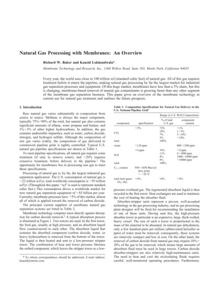
  • 1. Natural Gas Processing with Membranes: An Overview Richard W. Baker and Kaaeid Lokhandwala* Membrane Technology and Research, Inc., 1360 Willow Road, Suite 103, Menlo Park, California 94025 Every year, the world uses close to 100 trillion scf (standard cubic feet) of natural gas. All of this gas requires treatment before it enters the pipeline, making natural gas processing by far the largest market for industrial gas separation processes and equipment. Of this huge market, membranes have less than a 5% share, but this is changing; membrane-based removal of natural gas contaminants is growing faster than any other segment of the membrane gas separation business. This paper gives an overview of the membrane technology in current use for natural gas treatment and outlines the future prospects. 1. Introduction Table 1. Composition Specifications for Natural Gas Delivery to the U.S. National Pipeline Grid1 Raw natural gas varies substantially in composition from Range in U.S. Well Compositions source to source. Methane is always the major component, % of total component typically 75%-90% of the total, but natural gas also contains component specification U.S. gas content significant amounts of ethane, some propane and butane, and 1%-3% of other higher hydrocarbons. In addition, the gas <2% 72% <1% 18% 1-3% contains undesirable impurities, such as water, carbon dioxide, CO2 7% 3-10% nitrogen, and hydrogen sulfide. Although the composition of 3% >10% raw gas varies widely, the composition of gas delivered to total 100% commercial pipeline grids is tightly controlled. Typical U.S. water <120 ppm 800-1200 ppm natural gas pipeline specifications are shown in Table 1. <4 ppm 76% <4 ppm To meet pipeline specifications, all natural gas requires some H2S 11% 4-1000 ppm treatment (if only to remove water), and ∼20% requires 4% 1000-10000 ppm 8% >10000 ppm extensive treatment, before delivery to the pipeline.1 The total 100% opportunity for membranes lies in processing raw gas to meet C3+ content 950-1050 Btu/scf; these specifications. dew point: Processing of natural gas is, by far, the largest industrial gas < -20 °C separation application. The U.S. consumption of natural gas is total inert gases <4% 14% >4% ∼22 trillion scf/yr; total worldwide consumption is ∼95 trillion (N2, He) scf/yr. (Throughout this paper, “scf” is used to represent standard cubic feet.) This consumption drives a worldwide market for pressure overhead gas. The regenerated absorbent liquid is then new natural gas separation equipment of ∼$5 billion per year. recycled to the first tower. Heat exchangers are used to minimize Currently, membrane processes have <5% of this market, almost the cost of heating the absorber fluid. all of which is applied toward the removal of carbon dioxide. Absorber-stripper units represent a proven, well-accepted The principal current suppliers of membrane natural gas technology in the gas processing industry, and no gas processing separation systems are listed in Table 2. plant designer will be fired for recommending the installation Membrane technology competes most directly against absorp- of one of these units. Having said this, the high-pressure tion for carbon dioxide removal.2 A typical absorption process absorber tower in particular is an expensive, large, thick-walled, is illustrated in Figure 1. Two towers are used. In the first tower, heavy vessel. The size of such a tower is proportional to the the feed gas, usually at high pressure, and an absorbent liquid mass of the material to be absorped. In natural gas dehydration, flow countercurrent to each other. The absorbent liquid that only a few hundred parts per million (abbreviated hereafter as contains the absorbed component (carbon dioxide, water, or ppm) of water must be removed; consequently, these systems heavy hydrocarbon) is removed from the bottom of the tower. are relatively compact and low in cost. On the other hand, the The liquid is then heated and sent to a low-pressure stripper removal of carbon dioxide from natural gas may require 10%- tower. The combination of heat and lower pressure liberates 20% of the gas to be removed, which means large amounts of the sorbed component, which leaves the stripper tower as a low- absorbent fluid must be used in large towers. Carbon dioxide absorber-strippers are also relatively high-maintenance units. * To whom correspondence should be addressed. E-mail address: The need to heat and cool the recirculating fluids requires kaaeid@mtrinc.com. careful, well-monitored operating procedures. Furthermore,
  • 2. Figure 1. Typical natural gas absorber-stripper treatment process using amine absorbents to remove carbon dioxide. Similar processes use trieth- ylene glycol for water removal and lean oil for heavy hydrocarbon removal. corrosion is a critical maintenance issue. Amines are the most common sorbents for carbon dioxide, and the degradation of amines leads to corrosive mixtures that can destroy the system within a few days if left unchecked. Constant monitoring of the amine absorbent chemistry is needed. The need for regular maintenance and good operator care hinders the use of amine Figure 2. Structure of membranes used in membrane gas separation absorber-strippers in remote locations. processes: (a) anisotropic Loeb-Sourirajan membranes and (b) composite membranes. Membrane companies first broke into the natural gas process- ing industry in the 1980s, offering systems for carbon dioxide removal in competition with amine absorption. Membranes collect on the membrane surface. In addition, the gas is typically could gain a foothold in locations where the operational issues treated at relatively high pressures of 30-60 bar. Under these previously mentioned are especially problematic. The first conditions, the generally higher permeances of flat sheet membrane systems to separate carbon dioxide from natural gas membranes formed as spiral-wound modules can compensate were introduced by Grace Membrane Systems (a division of for their higher cost (on a $/(m2 membrane) basis), compared W.R. Grace), Separex (now part of UOP), and Cynara (now to hollow-fiber modules. Currently, both types of membrane part of Natco). These companies used anisotropic cellulose modules (spiral and hollow-fiber) are produced, by different acetate membrane that was produced using the Loeb-Sourirajan companies, and no clear winner has emerged. technique.3-5 Cellulose acetate membranes are still widely used. One trend that has emerged in commercial gas separation In the last 10 years, they have begun to be challenged by newer membranes is a move to composite membranes, in which a base membranes, such as the polyimide membranes (made by Medal anisotropic membrane is used as a highly porous support (to a division of Air Liquide)6 and perfluoropolymer membranes provide the mechanical strength required), and a thin layer of (made by ABB/MTR).7-9 permselective material (typically 0.2-1.0 µm thick) is deposited 1.1. Membrane Production Trends Making Membrane onto the support to perform the separation. Hollow-fiber Separations More Competitive. Current membranes used for membranes and flat sheet membranes can be made in this natural gas separation applications are produced as hollow fibers composite membrane form. Composite membranes, as shown or flat sheets packaged as spiral-wound modules. Hollow-fiber in Figure 2b, offer two key advantages over the conventional modules allow large areas of membrane to be packaged into Loeb-Sourirajan anisotropic membrane (shown in Figure 2a). compact membrane modules. This advantage proved decisive In Loeb-Sourirajan membranes, the porous support layer that in the choice of membranes for the separation of nitrogen from provides mechanical strength and the relatively dense surface air, which was an early large-scale membrane gas separation layer that performs the separation are formed at the same time process. Nitrogen production from air uses relatively low- from the same material. This limits the number of materials permeability membrane materials to process a clean, non- that can be used to make the membrane. It also means the plasticizing gas (air) at low pressures (generally <10 bar). separation properties are often compromised to make membranes Essentially all membrane nitrogen-from-air separation systems with sufficient mechanical strength. use hollow-fiber modules. Natural gas streams, in contrast, Composite membranes consist of a microporous support layer contain multiple components, some of which (water, carbon coated with one or more thin layers of a different polymer that dioxide, C4+ hydrocarbons, aromatics) degrade and plasticize performs the separation. Because the separation function and the membrane. Natural gas streams may also contain entrained the mechanical support function are separated, each can be oil mist, fine particles, and hydrocarbon vapors that can easily optimized separately, and the polymer best suited for each Table 2. Principal Suppliers of Membrane Natural Gas Separation Systems company principal natural gas separation membrane module type membrane material Medal (Air Liquide) CO2 hollow fiber polyimide W.R. Grace CO2 spiral-wound cellulose acetate Separex (UOP) CO2 spiral-wound cellulose acetate Cynara (Natco) CO2 hollow fiber cellulose acetate ABB/MTR CO2, N2, C3+ hydrocarbons spiral-wound perfluoro polymers silicone rubber Permea (Air Products) Water hollow fiber polysulfone
  • 3. Table 3. Typical Costs for Membranes, Membranes in 8-In.-Diameter Spiral-Wound Modules, and Module Skidsa Typical Cost ($/m2 of membrane) gas separation reverse osmosis (steel vessels (fiberglass vessels, type of unit and components) plastic components) membrane 20 5 membrane in spiral-wound 100 10-15 module form membrane modules in a skid 500 30-50 a Hollow-fiber reverse osmosis skids are normally less expensive on a per-square-meter-of-membrane basis; however, lower permeances offset much of this advantage. function can be used. Composite membranes allow high-cost polymer materials to be used economically in the separating layers. Tailor-made polymers with good separating properties often cost as much as $1000/kg-$10000/kg to synthesize. A Loeb-Sourirajan membrane generally uses ∼50 g of polymer/ (m2 membrane), so the material cost of membrane made from these high-cost polymers is in the $50/m2-500/m2 range. Composite membranes generally use a dense layer of polymer only 0.2-0.5 µm thick, so less than one gram of polymer/m2 of the high performance material is needed for a comparable Figure 3. Photograph showing the development of hollow-fiber membrane separation. The cost of this polymer is much more affordable, modules at Cynara, from the first 5-in. modules of the 1980s to the 30-in. at $1/m2-10/m2. The microporous support membrane for most diameter behemoths currently being introduced.10 Photo courtesy of Cynara Company (now part of NATCO Group, Inc.). natural gas applications can be made from conventional low- cost materials. Gas transport through dense polymer membranes is governed A second emerging trend in commercial membrane separa- by the expression tions is a move to larger membrane modules. Natural gas separations operate with high-pressure flammable gases that DiKi(pio - pil ) must be contained in code-stamped heavy steel vessels. The ji ) (1) impact of the cost of these vessels, flanges, valves, and pipes l on the system capital cost is illustrated in Table 3. Costs of module skids purchased for ultrafiltration/reverse osmosis where Jl is the volume (molar) flux (expressed in terms of cm3- applications are lower by a factor of 5-10. This difference (STP) of component i/(cm2 s)), l the membrane thickness, pl o reflects the higher production volumes and lower costs of the the partial pressure of component i on the feed side, and pi l plastic components and fiberglass housings that can be used in the partial pressure of component i on the permeate side. The water treatment processes. diffusion coefficient (Di) is an indication of the mobility of the Table 3 shows that the cost of membranes used in gas individual molecules in the membrane material, and the gas separation processes is a small fraction of the final membrane sorption coefficient (Ki, with units of cm3(STP) of component skid cost. High skid costs arise because of the many pressure i per cm3 of polymer per unit pressure) is an indication of the vessels, pipes, flanges, and valves that are required. One way number of molecules dissolved in the membrane material. The to reduce membrane skid cost is to increase the permeance of product DiKi can be written as Pi, which is called the membrane the membranes, allowing a smaller membrane area to be used permeability; this is a measure of the membrane’s ability to to treat the same volume of gas. All membrane manufacturers permeate gas. pursue this approach. Increasing the feed gas pressure also The best measure of a membrane’s ability to separate two reduces the membrane area required, and, hence, skid size, but gases i and j is the ratio of their permeabilities, Ri/j; this at the expense of larger compressors (higher capital cost) and parameter is called the membrane selectivity, and it can be increased energy consumption (higher operating cost). A third written as approach is to develop larger membrane modules and new skid designs. Currently, most modules, both spiral-wound or hollow- Pi [Di/Dj] fiber, are designed to fit in 8-in.-diameter housings. However, Ri/j ) ) (2) Pj [Ki/Kj] 12-in.-diameter spiral-wound modules are now being installed in some units, and some hollow-fiber module producers are also beginning to introduce very large modules, as shown in Figure The ratio Di/Dj is the ratio of the diffusion coefficients of the 3.10 These developments, combined with the use of lower-cost two gases and can be viewed as the mobility selectivity, which module skids,11 are likely to significantly reduce the cost of indicates the relative motion of individual molecules of the two future membrane systems and increase their long-term com- components i and j. The mobility selectivity is proportional to petitiveness. the ratio of the molecular size of the two permeants. The ratio Ki/Kj is the ratio of the sorption coefficients, which indicates the relative concentration of the components i and j in the 2. Permeation Theory membrane material. The sorption of a component increases with The factors that affect polymer membrane permeance and condensability of the component; therefore, the sorption selec- selectivity have been discussed in detail in several review tivity is proportional to the relative condensability of components articles12-15 and will only be briefly reviewed here. i and j.
  • 4. Table 4. Current Commercial Membrane Materials and Selectivities for Separation of Impurities from Natural Gas typical category of selectivities preferred over component polymer typical methane to be permeated material polymer used (%)a CO2 glassy cellulose acetate, 10-20 polyimide, perfluoro polymer H2S rubbery ether-amide block 20-30 co-polymer N2 glassy perfluoropolymer 2-3 Figure 4. Depiction showing the relative size (kinetic diameter) and rubbery silicone rubber 0.3 condensability (boiling point) of the principal components of natural gas. water rubbery or many >200 Glassy membranes generally separate using differences in size; rubbery glassy membranes separate using differences in condensability. C3+ hydrocarbons rubbery silicone rubber 5-20 a Selectivities are typical of those measured with high-pressure natural In polymer materials, diffusion coefficients decrease as the gas. molecular size increases, because large molecules interact with more segments of the polymer chain than do small molecules. nitrogen. These membranes minimize size selectivity and Hence, the mobility selectivity Di/Dj always favors the perme- maximize sorption selectivity, and, therefore, they are methane- ation of small molecules (such as water (kinetic diameter of permeable; but again, the selectivity is small. Finally, propane 2.65 Å) and carbon dioxide (kinetic diameter of 3.30 Å)) over and other hydrocarbons, because of their condensability, are larger ones (such as methane (kinetic diameter of 3.80 Å)). best-separated from methane with rubbery sorption-selective The sorption coefficient of gases in a polymer is a measure membranes. of the energy required for the gas to be sorbed by the polymer, Table 4 shows typical membrane materials and the selectivi- and it generally increases as the condensability increases. Hence, ties that can be obtained with good-quality membranes. These the sorption selectivity Ki/Kj favors absorption of the more- selectivities may seem low, compared to values commonly found condensable gas. Methane (which has a boiling point of 113 in the literature. This difference occurs because the literature K) is less condensable than almost all of the other components values are usually the ratios of the pure gas permeabilities. in natural gas, so the sorption selectivity usually favors Selectivities measured with high-pressure gas mixtures, espe- permeation of the nonmethane components. cially natural gas mixtures that contain plasticizing components The sorption selectivity term Ki/Kj for a particular gas pair is such as water, BTEX aromatics (benzene, toluene, ethylbenzene, relatively constant for all amorphous polymers, but the mag- and xylene), and other heavy hydrocarbons are usually signifi- nitude of the diffusion selectivity term Di/Dj is very dependent cantly lower. The values given in Table 4 are selectivities that on the nature of the polymer and, in particular, whether the might be reasonably expected by current commercial membranes polymer is above or below its glass-transition temperature. operating on “real” gas streams. Below the glass-transition temperature, the polymer chains are essentially fixed; the polymer is a rigid, tough, glassy material 3. Applications and the effect of differences in size of the permeating gases on their relative mobility is large. If the polymer is above its glass 3.1. Carbon Dioxide Removal. Carbon dioxide is a common transition temperature, motion of the polymer chains is possible. contaminant of natural gas and must be removed to a level of The polymer is then rubbery and elastic and the effect of <8% (usually <2%) to minimize corrosion of the pipeline. Until molecular size of the permeating gases on relative mobility is the introduction of membrane technology, the standard removal reduced. In extreme cases, if the polymer is plasticized by a technique was amine absorption.2 Amine absorption technology low-molecular-weight component that facilitates motion of the achieves almost complete removal of carbon dioxide. Generally, polymer chains, the mobility selectivity term can be quite small, ∼1% of the methane in the gas being treated is lost with the and for similarly sized permeating molecules, the ratio Di/Dj amine plant’s carbon dioxide vent gas stream, and another 1%- can approach unity. It follows that changing the membrane 4% of the methane is used as fuel to heat the reboiler of the material chemistry to obtain the optimum mobility selectivity amine stripper, so the total hydrocarbon losses are in the range term is the most widely used method for tailoring membrane of 2%-5%. Early membrane plants had difficulty in meeting materials and performance. this low hydrocarbon loss target. Better membranes and The molecular size and condensability of the principal improved process designs have since improved the competitive- components in natural gas, relative to methane, are shown ness of membranes. graphically in Figure 4. Water is small and condensable; The size of the absorbent recirculation rate, reboiler stripping therefore, it is easily separated from methane by both rubbery tower, pumps, and heat exchangers of an amine plant all increase and glassy polymers. Rubbery and glassy polymers can also in proportion to the mass of carbon dioxide to be removed, and separate carbon dioxide and hydrogen sulfide from natural gas. they are relatively independent of the volume of gas to be However, in practice, carbon dioxide is best separated by glassy treated. Only the high-pressure absorption tower increases in polymer membranes (maximizing size selectivity) whereas proportion to the volume of gas to be treated. Overall, this means hydrogen sulfide, which is larger and more condensable than an amine plant that is designed to treat 20 million scfd (scfd ) carbon dioxide, is best-separated by rubbery polymer membranes standard cubic feet per day) of gas that contains 5% carbon (maximizing sorption selectivity). Nitrogen can be separated dioxide would be only slightly more costly than an amine plant from methane by glassy polymers, but the difference in size is designed to treat 5 million scfd of gas that contains 20% carbon small, so the separations achieved are small. Alternatively, dioxide. Membrane plants, on the other hand, are able to treat rubbery polymers can be used to permeate methane over high-concentration gas streams much more efficiently than low-
  • 5. Figure 5. Typical membrane/amine hybrid plant for the treatment of associated natural gas produced in carbon dioxide/enhanced oil projects; a portion of the membrane plant’s permeate gas is usually used as a fuel for the amine absorption plant. concentration gas streams. A membrane plant designed to treat 5 million scfd of gas that contains 20% carbon dioxide would be less than half the size of a membrane plant designed to treat 20 million scfd of gas that contains 5% carbon dioxide. It follows that membrane plants are preferred for high-concentra- tion gas streams and amine plants are preferred for relatively low-concentration gas streams. Membrane plants, because of their simple flow schemes, are also generally preferred when processing small gas flows. Membrane plants processing <20 Figure 6. Schematic plot illustrating the effect of gas flow rate and carbon million scfd of gas are usually designed for unattended dioxide concentration in the gas on the choice of carbon dioxide removal operation. Amine plants are more complex and require careful, technology. This figure should be used with care, as site-specific issues well-monitored operating procedures, so that unattended opera- can produce very different results. tion is generally less practical. In principle, the combination of membranes for bulk removal of the carbon dioxide from natural gas with amine units as polishing systems offers a low-cost alternative to all-amine or all-membrane plants. However, this approach is limited to large plants where the overall savings in capital cost are large enough to offset the increased complexity of the plant, which now contains two separation processes.10,16 Hybrid plants have also been used in carbon dioxide flood-enhanced oil recovery projects in which carbon dioxide is injected into an oil formation to reduce the viscosity of the oil. Water, oil, and gas are removed from the formation; the carbon dioxide is separated from the gas produced and reinjected. Approximately 5% of U.S. oil is produced this way.17 In these projects, the composition and volume of the gas changes significantly over the lifetime of the project. The modular nature of membrane units lends itself to easy retrofitting of an existing amine plant, allowing the performance of the plant to be adjusted to meet the changing separation needs. Also, the capital cost of the separation system can be spread more evenly over the project lifetime. A block diagram of a membrane/amine plant is shown in Figure 5. In this design, the membrane unit removes two-thirds of the carbon dioxide, and the amine plant removes the remainder. A portion of the permeate gas from the membrane unit is used as fuel for the amine plant; the remainder is vented or reinjected. The combined plant is significantly less expensive than an all-amine or all-membrane plant. A schematic plot that illustrates the effect of gas flow rate and carbon dioxide composition on the choice of separation Figure 7. Photographs showing CO2 membrane separation plants. Top processes is shown in Figure 6. Similar figures with different photograph shows a 9 million scfd membrane plant designed to bring 6% numbers have appeared in the literature. Many site-specific CO2 gas to 2%; the plant is compact enough to be moved when the gas issues can change these plots. Membrane systems, for example, field is exhausted after a few years of operation (UOP/cellulose acetate membranes/spiral-wound modules; photo courtesy of UOP LLC). Bottom are strongly favored in offshore platforms that produce an photograph shows the world’s largest membrane CO2 removal plant; this increasing fraction of natural gas. An amine plant producer is a 500 million scfd unit that is designed to bring 5.7% CO2 gas to 2% might draw a different figure. The range of size and complexity (UOP/cellulose acetate membranes/spiral-wound modules). of membrane carbon dioxide separating plants is illustrated in Figure 7. very limited number of membrane materials, of which cellulose 3.1.1. Membranes Used. As shown previously in Table 4, acetate is probably the most common. This result surprises current membrane carbon dioxide separation plants use a many researchers who point to literature data that show the
  • 6. Figure 9. Graph showing that the difference between selectivities calculated from pure gas measurements and selectivities measured with gas mixtures can be large. The graph was constructed using data from Donohue et al.19 Figure 8. Robeson plot of CO2/CH4 selectivity versus membrane perme- for carbon dioxide/methane with cellulose acetate films. ability (permeance);18 the points shown are based on low-pressure pure- gas measurements. For comparison, the performance of commercial plasticizes the membrane, increasing the methane permeability membranes when used to separate carbon dioxide from high-pressure natural gas is shown on the same figure. far above its pure-gas value. The mixed-gas data shown in Figure 9 are limited to simple availability of much-better membrane materials. A widely CO2/CH4 mixtures; however, natural gas also contains water, used method of comparing the performance of various mem- and 1%-5% heavy hydrocarbons. These hydrocarbons are also brane materials is the selectivity/permeance plot popularized absorbed by the membrane and often have as large a plasticiza- by Robeson and shown in Figure 8.18 This plot shows the tion effect on membrane permeances as carbon dioxide. The selectivity for CO2/CH4 obtained from the ratio of pure-gas BTEX aromatics present in most natural gas at concentrations of 200-1000 ppm are particularly troublesome. At this con- permeabilities plotted against carbon dioxide permeability for centration, the BTEX aromatics can reduce membrane selectivity all the membrane materials then reported. The line that links by 30%-50%.24 The overall result of plasticization is to reduce the most-selective polymers at a particular carbon dioxide the membrane selectivity far below the pure-gas values. The permeability is called the “upper bound”, beyond which no magnitude of the effect is dependent on the gas composition material is currently known. The performance of today’s and pressure, and it is also related to the material used. Rubbery commercial membranes, when used with high-pressure natural polymers are less affected than glassy polymers. The 6-FDA gas, is also shown on this Robeson plot. Generally, commercial polyimides, which are a widely studied class of polymers that membranes that are in use have half the selectivity of the best often have very high pure-gas selectivities, are particularly upper bound materials. This difference reflects the effect of susceptible to plasticization.25 It follows from the aforemen- water, carbon dioxide, and heavy hydrocarbons present in the tioned discussion that it is the membrane’s gas permeance and gas on the membrane selectivity, as estimated from the ratio of selectivity at the expected operating conditions (mixed gas, high pure-gas permeances. pressure) that determines its suitability for practical applications. 3.1.2. Membrane Plasticization. The difference between Several strategies have been used to overcome membrane pure-gas membrane selectivity and the selectivity measured with plasticization. Pretreatment to remove aromatics and other heavy high-pressure natural gas is due to membrane plasticization, hydrocarbons from the gas is widely used (described below). which is a phenomenon that is well-known to industrial Crosslinking the membrane material often increases the mem- membrane system producers.19-23 The most important plasticiz- brane selectivity and makes the membranes more resistant to ing component in natural gas is carbon dioxide. At the high plasticization.23,25 However, fabricating cross-linked polymers pressures of natural gas operations, membrane materials absorb into thin membranes is not straightforward. Another strategy is 30-50 cm3(STP) of CO2/(cm3 polymer). This is equivalent to to use polymers such as the Teflon-like perfluoro polymers, 5-10 wt % of carbon dioxide in the polymer; not surprisingly, which are inherently resistant to plasticization by absorbed the membrane materials become plasticized. The absorbed hydrocarbons,7-9 as the membrane selective layer. carbon dioxide swells and dilates the polymer, increasing the In addition to plasticization, another problem with the glassy mobility of the polymer chains. One consequence is a sharp materials used to make CO2-selective membranes is physical drop in the polymer glass-transition temperature (Tg); another aging. The glassy polymers used in CO2-selective membranes is a decrease in the mobility (size) term in the selectivity are in a nonequilibrium state and, over time, the polymer chains equation (eq 2). Some old, but representative, results on the can slowly relax into a preferred higher-density-lower-perme- plasticization of cellulose acetate membranes are shown in ability form.26 This type of aging effect can reduce membrane Figure 9.19 Cellulose acetate has a low-pressure pure-gas (CO2/ permeabilities significantly over the average 2-5-year life of a CH4) selectivity of ∼40. At higher pressures, the pure-gas membrane used in natural gas service. selectivity (the ratio of pure-gas permeability) increases sharply, 3.1.3. Membrane Pretreatment. Pretreatment of natural gas because the permeability of pure carbon dioxide increases as feed streams to control the fouling, plasticization, and condensa- the pressure increases, but the pure-gas methane permeability tion of hydrocarbons on the membranes is required for all is relatively constant. When the same membranes are tested with membrane systems. Oil mist and particulates must always be CO2/CH4 mixtures, the membrane performance is quite different. removed, but for CO2 removal systems, treatment of the gas to The mixed-gas membrane selectivity decreases as the pressure control condensation of liquids on the membrane or excessive increases, because the membrane absorbs carbon dioxide, which plasticization of the membrane is also required.
  • 7. Figure 10. Graph showing the change in the phase envelope of CO2- containing natural gas during processing of the gas by a CO2-selective Figure 11. Natural gas pretreatment trains used in front of carbon dioxide membrane. membrane separation systems.4 The problem of liquid condensation on the membrane surface and the nature of the gas to be treated. Cellulose acetate is illustrated in Figure 10. This figure shows two natural gas- membranes, for example, are particularly sensitive to water and, phase envelope curves. These curves are calculated by computer therefore, glycol dehydration followed by silica bed drying process simulators, using equations of state that have been would be used for most streams. derived to predict the condensation point of complex natural- In Figure 11, the design labeled “maximum pretreatment” gas mixtures. At high temperatures, the natural-gas mixture would be used for a gas that contains high levels of carbon exists as a single phase. However, when the gas is cooled, heavy dioxide and a high concentration of heavy hydrocarbons (for hydrocarbons in the gas will reach their saturation values and example, gas produced as a byproduct of carbon dioxide flood condensation will occur. The dew point is the temperature at enhanced oil recovery projects). The pretreatment train labeled which condensation just begins and the gas enters the two-phase “minimum pretreatment” would be used for relatively hydro- region of the phase envelope. The dew-point temperature is carbon-lean gas that contains much smaller amounts of carbon dependent on the pressure and the concentration of heavy dioxide. hydrocarbons in the gas mixture. In the example calculation The importance of adequate pretreatment was not appreciated shown in Figure 10, the feed gas (A) is at 55 °C and 850 psia, by the builders of some of the first-generation membrane plants. comfortably above the dew point of the feed, which is ∼35 °C. Several early systems were damaged by plant upsets, which When the gas is processed by a membrane, carbon dioxide caused high levels of contaminants or liquids to reach the and some methane is removed in the permeate. Because membranes. Better plant designs are now used to control membranes are relatively impermeable to heavier hydrocarbons, membrane damage, and today’s membranes are also more these components are retained and concentrated in the residue robust. gas. This increase in heavy hydrocarbon concentration in the 3.1.4. System Design. The design of a membrane carbon gas causes the phase envelope to shift to higher temperatures, dioxide removal system will be dependent on the following as shown in Figure 10. The dew point of the residue gas (B) is factors: increased to ∼50 °C. A dew point of 50 °C is still below the (i) The selectivity and permeances of the membranes used temperature of the feed gas, but Joule-Thompson cooling, (ii) The carbon dioxide concentration of the gas and the because of expansion of the carbon dioxide permeating the separation required (for other components in the gas) membrane, cools the residue gas to 10- 15 °C below the feed (iii) The value of the gas (in the United States, the current gas. In the example shown, the combination of Joule-Thompson (2007) price of gas is $6-$7 per 1000 scf. In Nigeria, which is cooling and increased heavy hydrocarbon levels in the residue far from being as well-developed a gas market, the gas price gas is sufficient to bring the gas into the two-phase region of may be as low as $0.50 per 1000 scf, if the gas can be used at the phase envelope. Condensation of hydrocarbon liquids at the all) residue end of the membrane train would then likely occur. (iv) The location of the plant (on an offshore platform, the Condensation of this type will damage most membrane modules. weight, footprint, and simplicity of operation are critical; A solution to the condensation problem previously described onshore, total cost is more significant) is to heat the feed gas sufficiently so that the residue gas, even Block diagrams of two typical carbon dioxide removal plants when cooled by Joule-Thompson expansion, does not enter that treat natural gas with low CO2 concentration are illustrated the phase envelope. In the example shown, condensation would in Figure 12. Both plants are designed to treat 10 million scfd be avoided if the feed gas were heated to 65 °C. However, these of gas that contains 10% carbon dioxide. One-stage plants, high temperatures reduce the selectivity of the membrane. A which are simple, contain no rotating equipment, and require second solution is to remove some of the most condensable minimal maintenance, are preferred for very small gas flows. components in the gas to change the shape of the phase envelope In such plants, methane loss to the permeate is often 10%- before sending the gas to the membrane unit. This could be 15%. If there is no fuel use for this gas, it must be flared, which done using glycol absorption (to remove water), in combination represents a significant revenue loss. For gas wells that produce with cooling and condensation (to remove C4+ hydrocarbons). <1 MMscfd, one-stage membrane units, with their low capital Temperature swing adsorption is also used to remove small and operating costs, may make sense economically. As the amounts of C12+ hydrocarbons in the gas with carbon or silica natural gas stream increases in size, the methane loss from a bed adsorbents.16 In practice, feed gas heating and some form one-stage system and the resultant loss in revenue soon make of hydrocarbon removal technique are often used together. the choice of a one-stage system unattractive. Usually, the Two possible pretreatment trains for a carbon dioxide permeate gas is recompressed and passed through a second membrane separation plant are illustrated in Figure 11.4 The membrane stage. This second stage reduces the methane loss amount of pretreatment is dependent on the membranes used to a few percent, which is comparable to amine plant losses.
  • 8. onshore plants, and its installation could reduce methane loss to 3%-4%. However, offshore, the increase in weight, footprint, power consumption, and other cost-of-plant factors, may not be offset by the value of extra gas recovered. Amine absorption-stripper technology still has the bulk of the carbon dioxide natural gas treatment market. However, in some niche applications, such as offshore platforms treating high-carbon dioxide, membranes are already preferred. As membrane permeance and selectivity increase, membranes are beginning to compete in more mainstream applications. 3.2. Separation of C3+ Hydrocarbons. Natural gas usually contains propane, butane, and other higher hydrocarbons, and often the gas is close to saturation, with respect to these components. There are several reasons to control the concentra- tion of these heavy hydrocarbons in the gas. For example, at many remote natural gas production sites, only raw, untreated Figure 12. Flow scheme of one-stage and two-stage membrane separation gas is available to drive field compressor engines or power- plants to remove CO2 from natural gas (P/lCO2 ) 100 gpu; P/lCH4 ) 5 gpu). generating turbines. High levels of heavy hydrocarbons in the Because the one-stage design has no moving parts, it is very competitive gas cause pre-detonations and coking problems in these engines. with other technologies, especially if there is a use for the low-pressure permeate gas. Two-stage processes are more expensive, because a large Removal of the heavy hydrocarbons is needed to use the gas as compressor is required to compress the permeate gas. However, the loss of fuel. At other locations, large amounts of gas are produced as methane with the fuel gas is significantly reduced. a byproduct of oil production. Often, this gas cannot be transported easily to users. This “associated gas” is then usually compressed to high pressure and reinjected into the oil forma- tion. The heavy hydrocarbon content of these gases, although only a small volume fraction of the gas, may represent one- third of the mass of the gas. Separation of the heavy hydrocar- bons from the gas, followed by mixing of the heavies with the liquid oil, increases the amount of transportable hydrocarbon liquids produced. Finally, to avoid problems caused by con- densation of liquids, the dew point of U.S. natural gas is often reduced to -20 °C before delivery to the interstate pipeline. This means removing portions of the propane, butane, and higher Figure 13. Flow design of a combination two-stage and one-stage hydrocarbons from the gas. membrane system to remove CO2 from high CO2 concentration gas on an The current technology to separate heavy hydrocarbons from offshore platform. The CO2 concentration is reduced to ∼8%, which is low natural gas is cooling and condensation, or lean oil absorption. enough to allow pipelining to shore. The condensed heavy hydrocarbons separated from the gas The type of process design that might be used to treat a high- stream are then subjected to fractional distillation to recover concentration gas on an offshore platform in the Far East is the individual components. Because refrigeration is costly and shown in Figure 13. The design combines a one-stage and a uses large amounts of energy, there is interest in alternative two-stage system. The 50 million scfd of feed gas that contains techniques such as membrane gas separation. 30% CO2 is sent, after pretreatment, to two sets of membrane The competitiveness of membrane systems in this application modules. The first set of modules reduces the CO2 concentration is sensitive to the selectivity of the membrane for propane, from 30% CO2 to 15% CO2, producing a permeate stream that butane, and other hydrocarbons. These selectivities, in turn, are contains 82% CO2. This permeate gas is vented or reinjected. dependent on the pressure and composition of the gas being The second set of modules reduces the carbon dioxide concen- processed.27,28 Currently, silicone rubber membranes with a tration in the residue gas from 15% CO2 to 8% CO2. This is typical mixed-gas propane/methane selectivity of 3-5 and a the product gas that is piped to shore. The permeate from this butane/methane selectivity of 5-10 are used.29,30 Other more- set of modules contains 56% CO2; it contains too much selective materials have been reported; however, they are not hydrocarbon to be vented, so it is compressed and passed used in industrial systems.31,32 through a second membrane stage to produce a second-stage Engine fuel gas conditioning is currently the most widely permeate that contains 93% CO2 that can be vented. The second- used application of membranes for heavy hydrocarbon separa- stage residue that contains 30% CO2 is recycled to the front of tions.33 A flow diagram and a photograph of a recently installed the system. fuel gas conditioning unit (FGCU) are shown in Figure 14. At The product gas from the combined system contains 8% this site, the gas to be treated was being used to power a field carbon dioxide. This is well above the U.S. gas pipeline compressor gas engine. The gas was very rich, resulting in specification, but is low enough to control the corrosion of dry engine knocking and frequent shutdowns. A portion of the high- gas, and it allows the gas to be piped to shore, where the pressure gas (at 450 psia) was diverted from the pipeline and remaining carbon dioxide can be removed. The process design passed across the surface of a membrane that selectively shown in Figure 13 loses ∼7% of the hydrocarbons with the permeates the heavier components of the gas. Methane and carbon dioxide streams. This methane loss could be reduced ethane are retained by the membrane; propane, butane, C5+ by increasing the size of the second-stage compressor and hydrocarbons, and the BTEX aromatics all permeate preferen- membrane unit to treat some of the first-stage permeate. tially. The performance of the unit is shown in Table 5. The Installing this larger equipment would be worthwhile at most membrane selectivity increases as the size and condensability
  • 9. Figure 15. Flow scheme (top) and photograph (bottom) of a membrane dew point control unit (MTR/silicone rubber membranes/spiral-wound modules). Figure 14. Block diagram (top) and photograph (bottom) of a membrane fuel gas conditioning unit (FGCU) used for a field gas compressor engine The type of membrane system used to treat associated gas (MTR/silicone rubber membranes/spiral-wound modules). The membrane or control the dew point of pipeline gas is shown in Figure 15. modules are contained in the horizontal pressure vessels, and the unit High-pressure feed gas is sent to modules that contain a higher- produces 0.5-1.0 MMscfd of clean gas. hydrocarbon-selective membrane, which removes the higher Table 5. Performance Data for a Remote Site FGCU Removing C3+ hydrocarbons as the permeate stream. This stream is recom- Components from a Natural Gas Streama pressed and cooled by a fan-cooled heat exchanger to condense Gas Composition (mol %) higher hydrocarbons. The noncondensed bleed stream from the component feed gas conditioned fuel gas condenser will normally still contain more heavy hydrocarbons than the raw gas, so prior to returning the gas to the feed stream, propane 4.6 1.5 isobutane 2.0 0.5 the condenser bleed stream is passed through a second set of n-butane 1.5 0.3 membrane modules. The permeate streams from the two sets pentanes 1.7 0.3 of modules are combined, creating a recirculation loop around hexane 1.1 0.1 the condenser. The higher hydrocarbons are continuously C6+ 0.9 0.1 concentrated until their condensation point is reached and they balance methane and ethane total C3+ hydrocarbons 11.8 2.8 are removed as hydrocarbon liquids.34 The system shown in methane number 16 71 Figure 15 reduced the dew point of the feed gas by 25 °C. In a Data taken from ref 33. these systems, the cost of the compressor, visible in the right- hand side of the photograph in Figure 15, is often larger of each hydrocarbon in the stream increase, so the C5+ (sometimes significantly larger) than the cost of the membrane hydrocarbons with a selectivity of >20, are almost completely unit. Higher selectivity membranes would help in this applica- removed. In this particular application, the concentration of the tion, even if the membrane permeance were lower. Unfortu- C3+ hydrocarbons is reduced from 11.8% to 2.8%. The gas nately, no membrane that is significantly more selective than methane number (which is a measure similar to the octane silicone rubber has yet been found for higher hydrocarbon number of gasoline) increased from 16, which denotes a very separations. poor fuel, to 71, which denotes an excellent fuel. 3.3. Nitrogen Removal. Approximately 14% of U.S. natural The relative volume flows of the conditioned gas and the gas contains >4% nitrogen, which is the U.S. pipeline specifica- permeate recycle gas are dependent on the separation required. tion for this contaminant. Many of these high-nitrogen gas Generally, the streams will be approximately equal in size, in streams can be diluted with low-nitrogen gas to meet pipeline which case installation of the membrane unit will require ∼2%- specifications. If dilution is not practical, a nitrogen removal 4% of the pipeline gas to be diverted from the pipeline and unit must be installed. Cryogenic distillation is the only nitrogen through the gas conditioning unit. The process as shown uses removal process used on a large scale to date. As of 1999, 26 no new rotating equipment and, therefore, is ideal for remote nitrogen-removal cryogenic plants were in operation in the locations where maintenance is difficult. United States.35 Cryogenic plants are most suited to large gas
  • 10. Figure 17. Flow diagram of a 12 MMscfd membrane N2 removal plant installed on a high-N2 gas well in the Sacramento River Delta region of California. The design of a two-step nitrogen separation plant that was installed in a Sacramento River Delta gas field in California is shown in Figure 17. The feed gas contained 16% nitrogen. The Figure 16. One-stage membrane separations of a 10% N2/90% CH4 feed heating value of the gas was 900 Btu/scf. The pipeline would gas to produce a 50% N2/50% CH4 reject stream and a 4% N2/96% CH4 accept gas for dilution with low-nitrogen gas if the heating value product gas. This target can be achieved using (a) a CH4-permeable membrane with a selectivity of 6 or (b) an N2-permeable membrane with was increased to 990 Btu. To reach this target, the feed gas, at a selectivity of 17, which is far greater than that of the best membranes a pressure of 980 psia, was passed through three sets of modules known. in series. The permeate from the front set of modules was preferentially enriched in methane, ethane, and the C3+ hydro- fields that can deliver 50-500 million scfd of gas for 10-20 carbons, and the nitrogen content was reduced to 9%. These years. These large fields allow the high capital cost of the changes increased the heating value of the gas to 990 Btu/scf. cryogenic plant to be defrayed over several years. Many small This gas was compressed and sent to the pipeline. The residue nitrogen-contaminated gas wells are shut in for lack of suitable gas that contained 22% nitrogen was sent to a second membrane small-scale nitrogen separation technology. One new technology step where it was concentrated to 60% nitrogen. The permeate that has been attempted is pressure swing adsorption (PSA), from the second step contained 18% nitrogen and was recycled using molecular sieves that adsorb nitrogen.36,37 Another to mix with the feed gas. The residue gas from this unit was technology is membrane separation. then sent to a final small module to be further fractionated. This The nitrogen molecule is smaller than methane, so the module’s permeate gas, which contained 40% nitrogen, was used diffusion selectivity term in eq 2 always favors the permeation as fuel for the compressor engines. The final residue contained of nitrogen. However, methane is more condensable than 65%-70% nitrogen, and it was essentially stripped of all C3+ nitrogen, so the sorption selectivity term in eq 2 always favors hydrocarbons and was vented. the permeation of methane. Because the two terms are opposed, This unit recovered >95% of the hydrocarbon values for membranes can be made that selectively permeate nitrogen delivery to the pipeline; 2% of the hydrocarbons were used as (maximum selectivity of nitrogen over methane (RN2/CH4 ≈ 2.5)), compressor fuel, and the final 3% were vented with the separated or that selectively permeate methane (maximum selectivity of nitrogen. This system allowed 12 million scfd of gas with an methane over nitrogen (RCH4/N2 ≈ 3-4)). annual value of approximately $20 million to be produced. On The ability of nitrogen- and methane-selective membranes this basis, the system had a payback time of just a few months. to perform a target separation are compared in Figure 16. In 3.4. Water Removal. The removal of water from natural gas this comparison, a single-stage membrane unit is used to process is an extremely common operation and is usually performed a gas stream contaminated with 10% nitrogen into a product close to the wellhead to avoid hydrate formation and corrosion gas that contains 4% nitrogen and a waste gas that contains in the gas gathering system. By far, the most widely used 50% nitrogen (the latter of which is to be vented. Single-stage technology is absorption of water with diethylene or triethylene membrane units would rarely be used for these separations; glycol.40 Approximately 40 000 absorber-stripper units are in however, they do provide a good example for the difference operation at gas wellheads in the United States; there are many between the two types of membranes. A membrane unit able more in use around the world.41 The water content of high- to perform this separation would recover ∼93% of the hydro- pressure, water-saturated gas is usually ∼1000 ppm, and the carbons in the gas stream, which is sufficient for most small objective of the glycol absorption gas dryers is to bring this producers. The simulation was run iteratively, increasing the concentration to ∼100 ppm, which would be sufficient to membrane selectivity by small increments until the membrane prevent condensation, hydrate formation, and corrosion in the can just perform the separation required. In a single-stage pipeline. Because the mass of water removed by the dryer is process (rarely used), methane-permeable membrane with a small, glycol absorbers are much smaller than carbon dioxide methane/nitrogen selectivity of 6 can achieve the target separa- amine absorbers. A typical system that is designed to dry 10 tion. A selectivity of 6 is within striking distance of today’s million scfd of gas can be purchased for $100 000 and is fully most methane/nitrogen selective membranes (which have a automated for unattended operation, using pneumatic controls selectivity of 3-4).38 In contrast, a nitrogen-permeable mem- and valves and pumps. The operating costs are only a few cents brane must have a nitrogen/methane selectivity of 17 to achieve per 1000 scf of gas treated. the same separation. The best nitrogen-selective membrane The low cost and wide industry acceptance of glycol currently known has a nitrogen selectivity of 2.5, which is far dehydration systems has proved to be a stiff barrier to membrane below the value required; this is why methane-permeable competition. However, a few membrane dehydration systems membranes are used for this separation. Even so, multistep or have been built. Producing competitive membrane dehydration multistage systems are required in almost all applications.38,39 systems for natural gas treatment is not a membrane material In some applications, a combination of these two membranes performance problem. Membranes widely used to remove water proves to be the best solution. from air could be used; these membranes have good water
  • 11. Figure 18. Effect of permeate pressure on the efficiency of a membrane natural gas dehydration system. (Conditions: feed concentration, nH2OO ) 1000 ppm; residue concentration, nH2Ol ) 100 ppm; H2O/CH4 membrane selectivity, 500; feed pressure, 1000 psia.) Both CH4 loss and required membrane area decrease as the pressure ratio increases (or as the permeate Figure 19. Membrane system designs for dehydration of natural gas (H2O/ pressure decreases). CH4 selectivity ) 500; P/lH2O ) 2,000 gpu): (a) dehydration using a recycle compressor and (b) dehydration using a permeate sweep gas. permeances and water/methane selectivities of g500. The problem is a loss of methane, with the water vapor permeating One way to reduce the methane loss to an acceptable level is the membrane. Membrane units used to dry air also lose a to use a small vacuum pump to reduce the pressure of the fraction of the high-pressure air to the permeate. In air permeate gas to 1-2 psia.42,43 The membrane system then dehydration, this loss of air to the permeate is inconsequential; becomes small and the methane loss decreases to <1%. The with natural gas, a loss of even 1% of the feed gas makes the cost of such a membrane-vacuum system could be competitive process noncompetitive. with glycol dehydration, and in offshore applications, the small The reason these very high selectivity membranes lose footprint and low weight would be attractive. A membrane methane to the permeate gas is due to pressure ratio limits on system would have approximately one-fifth the weight and membrane performance. The importance of pressure ratio in footprint of a glycol absorption plant. However, the potential the separation of gas mixtures can be illustrated by considering hazard posed by air leaks contaminating the permeate gas has the separation of a gas mixture with water concentration of nH2OO to date made operators reluctant to send the gas to the plant at a feed pressure po. A flow of water across the membrane can fuel line, so the gas must be vented or flared, and even a methane only occur if the partial pressure of water on the feed side of loss of <1% normally is not economically acceptable. the membrane (nH2OOpo) is greater than the partial pressure of Another solution to this problem, shown in Figure 19a, is to water on the permeate side of the membrane (nH2Ol p ); that is, l operate the membrane system at a permeate pressure close to atmospheric pressure and then recompress the permeate gas. nH2OOpO g nH2Ol pl (3) Compressing the gas would cause almost all of the water vapor to condense and the remaining gas could be sent back to the It follows that the maximum separation achieved by the high-pressure feed. The problem with this system is cost of the membrane can be expressed as permeate compressor. This cost is larger than the cost of the membrane system, so this approach is not appealing. Yet another process design, which was developed by Air po nH2Ol g (4) Products and used in a few systems, is shown in Figure 19b.44,45 pl nH2OO In this process, a sweep gas of dry methane is passed across the permeate side of the membrane. The sweep gas increases That is, the separation achieved is always smaller than the the effective pressure ratio for water transport and reduces pressure ratio po/pl , no matter how selective the membrane. methane loss to ∼1%. The wet sweep gas-permeate mixture The effect of pressure ratio on system performance with high leaving the membrane unit is sent to a small secondary methane selectivity membranes is illustrated in Figure 18. A membrane drying loop, which produces clean dry methane to be recircu- with a water/methane selectivity of 500 is used to remove water lated. The complexity of the system and the need for a small from high-pressure natural gas. With this high selectivity compressor has limited use to a few offshore applications. membrane, the membrane area required to perform the separa- Because of all the problems previously outlined, membrane tion, and the amount of methane lost with the permeate gas technology is still struggling to break into the natural gas decreases sharply as the permeate pressure is reduced (increasing dehydration market. the pressure ratio). Clearly, operating at low permeate pressures 3.5. Other Membrane Applications. The separations of is beneficial. Nonetheless, even at a permeate pressure of 15 carbon dioxide, heavy hydrocarbons, nitrogen, and water are psia (atmospheric pressure), ∼5% of the feed gas methane is the principal applications of membrane technology in the natural lost with the permeate gas. This is too much gas to be useful as gas processing industry. At least one membrane plant to separate onsite low-pressure fuel; therefore, the bulk of the lost gas must helium from natural gas has been installed. However, most of be vented or flared. The loss of this much gas makes the process the world’s helium is produced as a byproduct of cryogenic noncompetitive. units that remove nitrogen from natural gas, so it is unlikely
  • 12. that more than a few membrane plants will be installed in the gas separation industry, especially in applications for the near future for this application. Membrane systems have also separation of carbon dioxide, nitrogen, and heavy hydrocarbons. been suggested as an alternative to amine absorption for the Improvements in polymer performance, membrane structure, separation of H2S from natural gas. Membranes with good H2S/ module fabrication, and process design have all contributed to CH4 selectivities and high permeances have been made,33 so increasing the potential range of applications for membranes membranes could be useful as part of a hybrid membrane-plus- in natural gas treatment. Membranes now give natural gas absorption process to process gas that contains high levels of producers an additional tool for upgrading the quality of the H2S. However, the complexity of this type of combination gas streams that they can deliver to the natural gas market. process is only justified for relatively large gas streams, which are limited in number. Literature Cited (1) Hugman, R. H.; Springer, P. S.; Vidas, E. H. Chemical Composition 4. Conclusions in Discovered and Undiscovered Natural Gas in the Lower-48 United States; Report No. GRI-90/0248; Energy and Environmental Analysis, Inc.: The use of membranes to process natural gas is a rapidly Arlington, VA, 1990. growing area of technology. More than 20 large (>100 million (2) Kohl, A. L.; Nielsen, R. B. Gas Purification, 5th Edition; Gulf scfd) carbon dioxide membrane removal plants have now been Publishing: Houston, TX, 1997. built, as well as many smaller systems. Membranes are the (3) Spillman, R. W. Economics of Gas Separation by Membranes. Chem. technology of choice for carbon dioxide removal systems on Eng. Prog. 1989, 85, 41. offshore platforms, and they are beginning to compete head- (4) Dortmundt, D.; Doshi, K. Recent Developments in CO2 Removal Membrane Technology. In Proceedings of the Laurance Reid Gas Condi- to-head with amine systems at onshore plants. As the technology tioning Conference, University of Oklahoma, Norman, OK, 2002; pp 22- matures, it seems likely that the membrane market share for 25. carbon dioxide separations will grow from the present low level, (5) Parro, D. Membrane CO2 SeparationsSACROC Tertiary Recovery especially for gases that have high carbon dioxide contents (20% Project. Presented at the AIChE Spring National Meeting, 1984. or higher). Cellulose acetate, which was the first material (6) Simmons, J. W.; Kulkarni, S.; Ekiner, O. M. Method for Separating developed for carbon dioxide separation applications, is still Hydrocarbon-Containing Gas Mixtures Using Hydrocarbon-Resistant Mem- branes, U.S. Patent Application No. 20040159233, August 19, 2004. the industry standard, but alternatives are now commercially (7) Baker, R. W.; Pinnau, I.; He, Z.; Amo, K. D.; DaCosta, A. R.; available. Over time, these new materials will increase the Daniels, R. Carbon Dioxide Gas Separation Using Organic-Vapor-Resistant competitiveness of membranes in the realm of carbon dioxide/ Membranes, U.S. Patent 6,572,680, June 3, 2003. natural gas separations. (8) Baker, R. W.; Pinnau, I.; He, Z.; Amo, K. D.; DaCosta, A. R.; Another growing application is the removal of heavy hydro- Daniels, R. Nitrogen Gas Separation Using Organic-Vapor-Resistant Membranes, U.S. Patent 6,579,341, June 17, 2003. carbons. Thus far, the most important use of membranes has (9) Merkel, T. C.; Pinnau, I.; Prabhakar, R.; Freeman, B. D. Gas and been in small (0.2-2.0 million scfd) streams to produce clean Vapor Transport Properties of Perfluoropolymers. In Materials Science of gas for field engines and turbines. This application is growing, Membranes for Gas and Vapor Separation; Yampolskii, Y., Pinnau, I., but a much larger market exists for units to recover heavy Freeman, B. D., Eds.; Wiley: Chichester, England, 2006. hydrocarbons as natural gas liquids from associated gas streams (10) Parro, D.; Blizzard, G.; Hornback, K. CO2 Separation Membraness A Critical Part of the Mallat CO2 Removal Facility. Presented at the produced on offshore platforms or at remote wells. These Laurance Reid Gas Conditioning Conference, University of Oklahoma, streams are large and not uncommon, and the value of the liquids Norman, OK, 2005. recovered by the membrane process can lead to short payback (11) Kaschemekat, J.; Fulton, D.; Wynn, N. Gas Separation Membrane times. The development of better, more-selective membranes Module Assembly, U.S. Patent Application No. 20060174762, 2006. would accelerate the development of these applications. (12) Baker, R. W. Membrane Technology and Applications, 2nd Edition; Wiley: Chichester, England, 2004. Nitrogen removal with membranes has also experienced (13) Freeman, B. D.; Pinnau, I. Polymeric Materials for Gas Separations. development over the past two years. Membranes offer a modest In Polymer Membranes for Gas and Vapor Separations; Freeman, B. D., separation selectivity of methane from nitrogen; however, the Pinnau, I., Eds.; American Chemical Society: Washington, DC, 1999; Vol. separation is difficult using any other technology, so membranes 733, pp 1-27. are still the low-cost solution in these applications. Most U.S. (14) Koros, W. J.; Fleming, G. K. Membrane-based Gas Separation. J. high-nitrogen gas can be brought to specification by blending Membr. Sci. 1993, 83, 1. (15) Pixton, M. R.; Paul, D. R. Relationships Between Structure and it with sufficient quantities of low-nitrogen gas. When dilution Transport Properties for Polymers with Aromatic Backbones. In Polymeric is possible, it is very difficult for membranes, or any other Gas Separation Membranes; Paul, D. R., Yampol’skii, Y., Eds.; CRC technology, to compete. However, site-specific issues can arise Press: Boca Raton, FL, 1994. requiring a membrane nitrogen removal unit, so this application (16) Anderson, C.; Siahaan, A. Case Study: Membrane CO2 Removal will likely grow, although it may be significant in the U.S. from Natural Gas, Grissik Gas Plant, Sumatra, Indonesia. Presented at the Laurance Reid Gas Conditioning Conference, University of Oklahoma, market only. Norman, OK, 2005. The dehydration of natural gas, which is a very common (17) Moritis, G. New Companies, Infrastructure, Projects Reshape natural gas treatment process, has proved disappointing as an Landscape for CO2 EOR in U.S. Oil Gas J. 2001, 99 (20), 68-73. application for membrane technology. A handful of systems that (18) Robeson, L. M. Correlation of Separation Factor versus Permeability are based on membranes and process designs developed for air for Polymeric Membranes. J. Membr. Sci. 1991, 62, 165-185. (19) Donohue, M. D.; Minhas, B. S.; Lee, S. Y. Permeation Behavior dehydration have been installed; however, current membrane of Carbon-Dioxide Methane Mixtures in Cellulose-Acetate Membranes. J. technology cannot compete with glycol absorption, except in a Membr. Sci. 1989, 42 (3), 197-214. few offshore operations where size and weight considerations (20) Sanders, E. S. Penetrant-induced Plasticization and Gas Permeation favor a membrane solution. Therefore, the dehydration of natural in Glassy Polymers. J. Membr. Sci. 1988, 37 (1), 63-80. gas with membranes is likely to remain a niche application. (21) Visser, T.; Koops, G. H.; Wessling, M. On the Subtle Balance The issue is not the availability of good membranes, but rather between Competative Sorption and Plasticization Effects in Asymmetric Hollow Fiber Gas Separation Membranes. J. Membr. Sci. 2005, 252, 265- the pressure ratio needed to allow the membrane to be used. 277. In summary, membrane-based removal of natural gas con- (22) Wind, J. D.; Paul, D. R.; Koros, W. J. Natural Gas Permeation in taminants is the most rapidly growing segment of the membrane Polyimide Membranes. J. Membr. Sci. 2004, 228 (2), 227-236.
  • 13. (23) Wind, J. D.; Staudt-Bickel, C.; Paul, D. R.; Koros, W. J. The Effects (36) Mitariten, M. Economic Nitrogen Removal. Hydrocarbon Eng. of Crosslinking Chemistry on CO2 Plasticization of Polyimide Gas 2004, 9 (7), 53-57. Separation Membranes. Ind. Eng. Chem. Res. 2002, 41 (24), 6139-6148. (37) Dolan, W. ; Mitariten, M. Nitrogen Removal from Natural Gas (24) Vu, D. Q.; Koros, W. J.; Miller, S. J. High Pressure CO2/CH4 with Molecular Gate Technology. Presented at the Laurance Reid Gas Separation Using Carbon Molecular Sieve Hollow Fiber Membranes. Ind. Conditioning Conference, University of Oklahoma, Norman, OK, February Eng. Chem. Res. 2002, 41 (3), 367-380. 2001. (25) Staudt-Bickel, C.; Koros, W. J. Improvement of CO2/CH4 Separa- (38) Baker, R. W.; Lokhandwala, K. A.; Pinnau, I.; Segelke, S. Methane/ tion Characteristics of Polyimides by Chemical Crosslinking. J. Membr. Nitrogen Separation Process, U.S. Patent 5,669,958, September 23, 1997. Sci. 1999, 155 (1), 145-154. (39) Baker, R. W.; Lokhandwala, K. A.; Wijmans, J. G.; DaCosta, A. (26) Huang, Y.; Paul, D. R. Physical Aging of Thin Glassy Polymer R. Nitrogen Removal from Natural Gas Using Two Types of Membranes, Films Monitored by Gas Permeability. Polymer 2004, 45 (25), 8377-8393. U.S. Patent 6,630,011, October 7, 2003. (27) Raharjo, R. D.; Freeman, B. D.; Sanders, E. S. Pure and Mixed (40) Choi, D. W. How to Buy Glycol Dehydrators. Hydrocarbon Gas CH4 and n-C4H10 Sorption and Dilation in Poly(dimethylsiloxane). J. Process. 2006, 85, 69. Membr. Sci. 2007, 292 (1), 45-61. (41) Graham, J. F.; Krenek, M. R.; Maxson, D. J.; Pierson, J. A.; (28) Raharjo, R. D.; Freeman, B. D.; Paul, D. R.; Sarti, G. C.; Sanders, Thompson, J. L. Natural Gas Dehydration: Status and Trends, Final Report, E. S. Pure and Mixed Gas CH4 and n-C4H10 Permeability and Diffusivity Report No. GRI-5093-810-2545, Gas Research Institute, Chicago, IL, in Poly(dimethylsiloxane). J. Membr. Sci. 2007, 306 (1), 75-92. January 1994; p 97. (29) Baker, R. W.; Wijmans, J. G. Membrane Separation of Organic Vapor Streams. In Polymeric Gas Separation Membranes; Paul, D. R., (42) Ohlrogge, K.; Brinkmann, T. Natural Gas Cleanup by Means of Yampolskii, Y. P., Eds.; CRC Press: Boca Raton, FL, 2000. Membranes. Ann. N.Y. Acad. Sci. 2003, 984 (1), 306-317. (30) Ohlrogge, K.; Peinemann, K.-V.; Wind, J.; Behling, R.-D. The (43) Sulpizio, T. E.; Minhas, B. S. Gas Dehydration by Membranes: Separation of Hydrocarbon Vapours with Membranes. Sep. Sci. Technol. Industrial Feasibility, Final Report, Report No. GRI-5089-222-1934, Gas 1990, 25 (13-15), 1375. Research Institute, Chicago, IL, June 1993. (31) Pinnau, I.; Lokhandwala, K.; Nguyen, P.; Segelke, S. Separation (44) Stookey, D. J.; Jones, K.; Kalthod, D. G.; Johannessen, T. of Low-Boiling Gases Using Super-Glassy Membranes, U.S. Patent 5,688,- Membrane DehydratorssA New Alternative for Drying High Pressure 307, November 18, 1997. Gases. In Proceedings of the 1996 Membrane Technology/Planning (32) Schultz, J.; Peinemann, K.-V. Membranes for Separation of Higher Conference: Business Communications Co., Inc.: Newton, MA, October Hydrocarbons from Methane. J. Membr. Sci. 1996, 110 (11), 37-45. 29, 1996. (33) Jariwala, A.; Lokhandwala, K.; Baker, R. W. Only Raw Sour Gas (45) Auvil, S. R.; Choe, J. S.; Kellog, L. J. Use of Membrane Separation for Engine Fuel? Proven Membrane Process Cleans Gas for Engines. to Dry Gas Streams Containing Water Vapor, U.S. Patent 5,259,869, Presented at the Laurance Reid Gas Conditioning Conference, University November 9, 1993. of Oklahoma, Norman, OK, 2006. (34) Wijmans, J. G. Membrane Process and Apparatus for Removing ReceiVed for reView August 8, 2007 Vapors from Gas Streams, U.S. Patent 5,071,451, December 10, 1991. ReVised manuscript receiVed November 30, 2007 (35) Tannehill, C. C. Nitrogen Removal Requirement from Natural Gas; Accepted December 4, 2007 Topical Report, Report No. GRI-99/0080; Gas Research Institute, Chicago, IL, May 1999. IE071083W