
Empfohlen
Empfohlen
Weitere ähnliche Inhalte
Was ist angesagt?
Was ist angesagt? (10)
Andere mochten auch
Andere mochten auch (17)
Ähnlich wie Practicing Oil Analysis - It's All About Size Film Thickness
Ähnlich wie Practicing Oil Analysis - It's All About Size Film Thickness (20)
Mehr von filtermag
Mehr von filtermag (14)
Kürzlich hochgeladen
Kürzlich hochgeladen (20)
Practicing Oil Analysis - It's All About Size Film Thickness
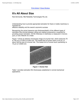
- 1. Practicing Oil Analysis - It's All About Size 1/9/09 11:26 PM Print Article | Close Window It's All About Size Rob Simmonds, R&t Reliability Technologies Pty Ltd. Understanding how to provide appropriate lubrication for fixed or mobile machinery is important for effective reliability and the owner’s economic success. Recognizing the actual clearance size (thickness/depth) of the different types of lubrication films formed between rolling and rotating components is essential for providing proper lubrication. Oil film thickness in machinery is measured in microns (µm), or one millionth of a meter. Figure 1 shows an electron microscope image of a human hair, which measures 70 to 100 µm or 0.003 to 0.004 inch. The lowest limit of human vision is 40 µm, or about half the size of a human hair. The lowest limit of human touch (sensitivity) is 15 µm or 0.0005 inch. Figure 1. Human Hair Table 1 provides lubrication film thicknesses established in normal mechanical applications. http://www.oilanalysis.com/article_printer_friendly.asp?articleid=987 Page 1 of 9
- 2. Practicing Oil Analysis - It's All About Size 1/9/09 11:26 PM Table 1. Lubrication Film Clearances During Normal Operation Some applications form thicker oil films such as journal bearings and hydrostatic bearings in combustion engines. However, in engines there are still instances of tight clearance oil films such as cam lobes, piston rings, and oiling rings that run at less than 1 µm fluid film thickness. The lubrication film thickness developed in a mechanical application impacts the typical maintenance. Without considering the lubrication film thickness, it is likely the typical maintenance will only prevent the entry of visible dirt and debris contaminants larger than 40 µm. Contaminants sized from 2 to 20 µm are typically the most damaging, and excluding these contaminants from entry is necessary for improved plant and machinery reliability. R&T Lab's reliability tests indicate that fine, hard airborne environmental contaminants ranging in size from 2 to 20 µm cause 80 to 90 percent of abnormal wear in oil- and grease-lubricated machinery. Most Frequent Ingress Points for Contamination For combustion engines, compressors and blower-type applications, contaminants generally enter through the "clean" air induction system. On gear drives, transmissions, differentials and hydraulics, contaminants enter through breather (atmospheric pressure equalization) vents. Grease-lubricated applications are commonly contaminated during the relubrication process. In a contaminated environment, the grease can carry the contaminants into the lubricated area. Understanding the behavior of the environmental contaminants is important in selecting the proper contamination control measures. Figure 2 shows the distance and time that fine particles are able to remain suspended in the normal air flow. The most damaging sizes of hard contaminants are particles ranging from 2 to 20 µm, medium mesoscale range, which is not visible to the human eye. Figure 2 indicates that larger particles can stay suspended in the air flow for a kilometer or more, indicating mobility and the continual presence of environmental contamination. Such http://www.oilanalysis.com/article_printer_friendly.asp?articleid=987 Page 2 of 9
- 3. Practicing Oil Analysis - It's All About Size 1/9/09 11:26 PM contaminants are to be expected even if there is no visual indication. In summary, the lubrication film thickness formed in the majority of machinery will not provide enough film thickness to protect the application if normal environmental air flow is permitted to have unfiltered access to the lubricant. Figure 2. Particle Travel and Suspension Time from Point of Origin Environmental Contamination of Engines, Compressors and Blowers If filter servicing frequency is increased to prevent overloading, then the filters of most well-designed systems will not be plagued with contaminants. When monitoring air induction-type applications (such as engines, compressor and blowers) the lubricant's particle count, viscosity, ferrous density and acid number (AN) must be monitored at intervals that allow any changes to be visually investigated by ferrogram or wear debris analysis. This ensures no wear damage has occurred before the next sample is taken. Photos in Figure 3 show the piston rings from a 60-foot patrol boat servicing Hong Kong Harbor. This application is designed to perform in a dust-free environment operating off-shore, but as shown, the piston ring sealing face has been damaged by fine silica quartz crystals. These crystals travel in the air flow from garbage refuse sites and construction sites across the harbor, and then they are ingested by the engines. Gear Drives, Transmissions and Hydraulic Systems If unfiltered air flow is allowed into the lubricated area of gear drives, transmissions or hydraulic systems, the repetitive thermal cycling of the application as it heats and cools will carry airborne contaminants into the lubricated area. The expansion rate for air mixture of gases is 10 percent change for every 10°C shift in temperature. As the drive heats and cools the air, it expands and contracts, leaving behind the http://www.oilanalysis.com/article_printer_friendly.asp?articleid=987 Page 3 of 9
- 4. Practicing Oil Analysis - It's All About Size 1/9/09 11:26 PM contaminants introduced to the system. This process loads the oil with contaminants and forms a homogeneous mixture that damages machine surfaces, accelerates wear debris contamination and continues the wear cycle. Measuring a lubricant's particle count, viscosity, ferrous density and AN should be a part of every condition monitoring program in gear drives, transmissions or hydraulic systems. If abnormalities are detected, then a ferrogram or wear debris analysis can check for destructive wear. Because of the continual filtering of hydraulic systems, breather filters can be designed more for air flow than to remove submicron particles unfiltered gear drives and transmissions also need a high-quality breather filter. The photos in Figure 4 show wear debris and contaminants that were created by airborne contaminants. Common dust contaminated with fine volcanic ash entered the forklift's differential through the breather vent. This contamination led to the failure of the planetary hub. In another example, research was conducted to evaluate environmental contamination on gearbox breather vents in a one year-old plastic blow molding factory. The plant's epoxy-sealed floor is wet mopped twice a week, making it cleaner than the average factory. Figure 5a shows the left-side machine layout on the factory's blow molding floor. Figure 5b from the same plant is an extruder screw gearbox. Note its clean condition. Figure 5c is the extruder screw gearbox breather vent. The breather filter was removed, washed with super clean solvent and the washing solvent was filtered. Figure 5d shows an overview of the contamination, at 100X magnification, washed out of the gearbox breather vent filter. Figures 5e and 5f show the debris at 500X magnification. The debris consists of plastic particles, fluff, fibers and dirt. Gearbox and transmission oil reservoirs are generally filled to 30 to 50 percent of gear case volume to provide adequate lubrication and to control lubricant expansion, foaming and churning. Experience has shown that periodic monitoring of the lubricant cleanliness level can protect plant machinery and control early machine wear and damage. Tables 2 through 5 show cleanliness levels of machines monitored for abnormal wear. Maintaining contamination levels in lubricants can extend equipment life. Once clean lubricant levels in plant and equipment are achieved, the lubricant's life will also be extended, reducing wear and tear to near zero. Table 2 indicates the cleanliness levels required in different lubricating fluids to prevent wear. By identifying the elevated contaminant levels, one can isolate the contaminant particles and remove them by following a couple of maintenance steps. Removing the contaminant and resulting wear debris usually allows machinery to return to normal wear modes. Subsequently, maintaining low contamination levels often achieves a service life longer than expected. Lubricant and Plant Monitoring Frequency Machinery manufacturers often suggest a lubricant sampling interval, however, this should be used only as a guideline. The operator is the best judge of sampling intervals. He or she should ask some pertinent questions in determining a sampling interval, such as: http://www.oilanalysis.com/article_printer_friendly.asp?articleid=987 Page 4 of 9
- 5. Practicing Oil Analysis - It's All About Size 1/9/09 11:26 PM What is the failure history? How costly is a failure? In repairs, lost production and life and safety? Have operating conditions changed, putting additional stress on the machine? In general, a monthly or quarterly sample interval is appropriate for industrial machinery. Answers to these questions will help decide the appropriate regimen. When beginning a new program, start with a monthly interval and then extend it as test results and experience allow. Tables 4 and 5 provide a guide to start with. After two or three test results, there should be enough information to extend or shorten the intervals as necessary, depending upon the analysis results. Basic testing should include ISO particle count, viscosity cSt at 40°C, water, oxidation, ferrous density and spectrometer wear elements. (Click Image to Enlarge) Table 2. Machinery damage will occur if contaminating wear debris and particle levels are permitted to reach the "start testing" level. (Click Image to Enlarge) Table 3. Recommended Machine Type/Cleanliness Code Note: These code numbers apply to later versions of the laser particle counting techniques. Particles at 2µm/5µm/15µm per cc of lubricant. (Click Image to Enlarge) Table 4. Recommended Testing Slate and Interval for Fixed Equipment Note: Basic testing should include ISO particle count, viscosity cSt at 40°C, water, oxidation, ferrous density and spectrometer wear elements. (Click Image to Enlarge) Table 5. Recommended Testing Slate and Interval for Mobile Equipment Note: Basic testing should include ISO particle count, viscosity cSt at 40°C, water, oxidation, ferrous density and spectrometer wear elements. Figure 3. Images at 500X http://www.oilanalysis.com/article_printer_friendly.asp?articleid=987 Page 5 of 9
- 6. Practicing Oil Analysis - It's All About Size 1/9/09 11:26 PM Note burn mark and subsequent wear surface delamination. Note the compression ring's sealing face fatigue cracking occurring from the hard particle damage to the piston rings as the environmental contaminants travel down the bore past the rings. The piston rings on these 396 Detroit V12s engines were continually damaged and required replacement every four to six months. Closeup of where the nonthrust side of the liner meets the thrust side. Note how fine hard contamination ingression has proceeded to polish away the left- side cross-hatch hone marks, leaving scored lines where hard particles have driven down the bore by the piston. Silica crystals (maybe fly ash from the shape) at 1,000X 5 to 15 µm . These fine hard airborne particles were removed from the top of the piston rings. http://www.oilanalysis.com/article_printer_friendly.asp?articleid=987 Page 6 of 9
- 7. Practicing Oil Analysis - It's All About Size 1/9/09 11:26 PM Figure 4a. RS Gear Drive Fork Lift Figure 4b, 4c. Broken Bearing Steel Wear Debris Figure 4d, 4e. Volcanic Ash Crystals http://www.oilanalysis.com/article_printer_friendly.asp?articleid=987 Page 7 of 9
- 8. Practicing Oil Analysis - It's All About Size 1/9/09 11:26 PM Figure 5a Figure 5b Figure 5c http://www.oilanalysis.com/article_printer_friendly.asp?articleid=987 Page 8 of 9
- 9. Practicing Oil Analysis - It's All About Size 1/9/09 11:26 PM Figure 5d Figure 5e Figure 5f Please reference this article as: Rob Simmonds, R&t Reliability Technologies Pty Ltd., "It's All About Size". Practicing Oil Analysis Magazine. January 2007 Issue Number: 200701 Practicing Oil Analysis Best Practices http://www.oilanalysis.com/article_printer_friendly.asp?articleid=987 Page 9 of 9