
Empfohlen
Weitere ähnliche Inhalte
Was ist angesagt?
Was ist angesagt? (20)
Ähnlich wie Measurement of unknown resistance by using a neon flash lamp and a capacitor3 (autosaved)
Ähnlich wie Measurement of unknown resistance by using a neon flash lamp and a capacitor3 (autosaved) (20)
Kürzlich hochgeladen
Kürzlich hochgeladen (20)
Measurement of unknown resistance by using a neon flash lamp and a capacitor3 (autosaved)
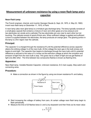
- 1. Measurement of unknown resistance by using a neon flash lamp and a capacitor Neon Flash Lamp: The French engineer, chemist, and inventor Georges Claude (b. Sept. 24, 1870, d. May 23, 1960) invent neon flash lamp on December 11, 1910, in Paris A neon lamp (also neon glow lamp) is a miniature gas discharge lamp. The lamp typically consists of a small glass capsule that contains a mixture of neon and other gases at a low pressure and two electrodes (an anode and a cathode).The two electrodes are very near to each other but not touching. The cathode consist of spiral of thick wire. When sufficient voltage is applied and sufficient current is supplied between the electrodes, the lamp produces an orange glow. The glowing portion in the lamp is a thin region near the cathode. Principal: The capacitor C is charged through the resistance R until the potential difference across capacitor attains the striking voltage VS of the neon bulb. At this voltage the neon gas in the bulb ionizes and begins to emit light. The capacitor then begins to discharge through the neon bulb until it’s potential difference is reduced to the value of Ve known as the extinction voltage at which the ionization and emission of light from the neon bulb is stop. This gives rise to a flash of light and we get flashes of light one after other. The time between two consecutive flashes is known as flashing time. Apparatus: Neon flash lamp, Variable Resistor Capacitor, Unknown resistance, D.C main supply, Stop watch and connecting wires. Procedure: Make a connection as shown in the figure by using one known resistance R1 and battery. Start increasing the voltage of battery from zero. At certain voltage neon flash lamp begin to flash periodically. Measure the time of 20 flashes twice (t1 and t2) by stopwatch and then finds out its mean value t = t1 + t2 2
- 2. Calculate the time period T of neon lamp by dividing mean with 20 T = t 20 Repeat the steps (2, 3, 4) for two other known resistances (R2and R3) and calculate time period T for each resistance Plot a graph between resistance R on x-axis and time period Ton y-axis. It will be straight line. Now put the unknown resistance RX in place of variable resistor and calculate time period T by repeating above steps (2,3,4) and note it. Mark the point 'A' on the time period axis for time period of unknown resistance. Now mark a point 'B' on straight line corresponding to point 'A'. Draw a vertical line BC from point 'B' to x-axis. Read the value of C on x-axis. It is the value of unknown resistance. Observations and Calculation: GRAPH: Resistance on X-axis and Flashing Period on Y-axis 0 0.2 0.4 0.6 0.8 1 1.2 0 1 2 3 4 5 6 FlashingPeriodT (sec) Resistance R (MΩ) 0.75s A B C S. No. Resistances R(MΩ) Time of 20 flashes Mean Time t1+t2 Flashing Period T=t/20 t1(sec) t2(sec) 1. 1 4.93 4.67 4.8 0.24 2. 3 13.7 13.9 13.8 0.690 3. 5 22.3 22.4 22.35 1.117 4. X 14.9 15.1 30 0.75 Result: The value of unknown resistance Rx is 3.26MΩ corresponding to 0.75s on Y-axis 2 t= 3.26MΩ
- 3. Precautions: Least count of stop watch should be noted and graduation on stopwatch should be studied carefully before starting the experiment. The applied voltage should be kept constant through out the experiment. The capacitance of the capacitor should be 2µF to 5µF so as to get a measureable rate of flashing with the unknown resistance. The resistances should be of the mega ohms to get measurable time period In order to avoid error due to photo electric effect the experiment should be performed in a dark room or the neon bulb may be enclosed in a box with a small sighting hole. The DC mains voltage should be greater than the striking voltage for the lamp. Reading for time and striking voltage should be noted at the instant when the lamp just glows. Sources of Error: Inaccuracy of stopwatch. Loose connections Voltage flections. Necked wire should not be touched when the switch is on. Before starting the experiment get the circuit checked by your teacher Viva Voce: Q.1 What is meant by striking voltage? Ans. The potential difference across a neon lamp at which it begins to glow periodically is called striking voltage. Generally It's value is 150-170V. Q.2 What is meant by extinction voltage? Ans. That certain voltage at which neon lamp extinguishes and stop glowing is called extinction voltage. Generally it's value is about 140V. Q.3 What do you mean by flashing period? Ans. Time between two consecutive glows of the neon lamp is flashing period. Q.4 Why it is not possible to determine the value of low resistance using neon flash lamp? Ans. It is not possible to measure low resistance because at low resistance, flashing of neon lamp is so quickly that we can't measure accurate flashing period. Q.5 Is the charging rate of capacitor constant? Ans. No, because when we plot graph between RC and q we get curve of exponential form that shows at first charge deposit on capacitor rapidly but afterward charges rate decreases. So charging rate is not constant. Q.6 How much time does capacitor take to charge upto the full voltage applied? Ans. theoretically, time required to charge a capacitor to full voltage applied is infinity as seen from the relation, V=Vo(1-e-t/CR) Q.7 Summarize some important application of neon flash lamp? It is used for the spectrometer work as a source of light in the laboratory.
- 4. It is used as bed room lamps as it consumes negligible energy. It used for traffic signal and at airports due to high visibility. Small neon lamps are most widely used as visual indicators in electronic equipment and appliances, due to their low power consumption, long life, and ability to operate on mains power. It is also used in neon sign boards for decoration and advertisements purposes. Neon lamps with several shaped electrodes were used as alphanumerical displays known as Nixie tubes. These have since been replaced by other display devices such as light emitting diodes, vacuum fluorescent displays, and liquid crystal displays.