

Empfohlen
Weitere ähnliche Inhalte
Was ist angesagt?
Was ist angesagt? (20)
Ähnlich wie Manual zmnhxd1
Ähnlich wie Manual zmnhxd1 (20)
Mehr von Domotica daVinci
Mehr von Domotica daVinci (20)
Kürzlich hochgeladen
Kürzlich hochgeladen (20)
Manual zmnhxd1
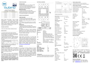
- 1. 3-Phase Smart Meter ORDERING CODE Z-WAVE FREQUENCY ZMNHXD1 868,4 MHz ZMNHXD2 921,4 MHz ZMNHXD3 908,4 MHz ZMNHXD4 869,0 MHz ZMNHXD5 916,0 MHz ZMNHXD8 865,2 MHz Qubino 3-Phase Smart Meter is used for energy measurements in three-phase electrical power network and can be used in residential, industrial and utility applications. The module measures energy directly in 4-wire networks according to the principle of fast sampling of voltage and current signals. It is designed to be mounted on DIN rail. PACKAGE CONTENTS 3-Phase Smart Meter Module, Installation Manual INSTALLATION 1. To prevent electrical shock and/or equipment damage, disconnect electrical power at the main fuse or circuit breaker (if it is compliant to standard IEC947- 2) before installation and maintenance. 2. Be aware that even if the circuit breaker is off, some voltage may remain in the wires — before proceeding with the installation, be sure no voltage is present in the wiring. 3. Take extra precautions to avoid accidentally turning on the device during installation. 4. Connect the module exactly according to the diagram. 5. Place the antenna as far as possible from metal elements as they may cause signal interference. 6. Do not shorten the antenna. Danger of electrocution! Installation of this module requires a great degree of skill and may be performed only by a licensed and qualified electrician. Please keep in mind that even when the module is turned off, voltage may still be present in the module’s terminals. Note! Do not connect the module to loads exceeding the recommended values. Connect the module exactly as shown in the provided diagrams. Improper wiring may be dangerous and result in equipment damage. Electrical installation must be protected by over current protection with rated breaking capacity up to 80A and must be used according to wiring diagram to achieve appropriate overload protection of the module. Z-WAVE INCLUSION AUTO-INCLUSION 1. Enable inclusion mode on your Z-Wave controller 2. Connect the module to the power supply 3. Auto-inclusion will be initiated within 5 seconds of connection to the power supply and the module will automatically enroll in your network MANUAL INCLUSION 1. Connect the module to the power supply 2. Enable inclusion mode on controller and press and hold the S (Service) button for at least 2 seconds 3. A new device will appear on your dashboard Z-WAVE EXCLUSION/RESET Z-WAVE EXCLUSION 1. Connect the module to the power supply 2. Enable exclusion mode on your Z-Wave controller and press and hold S (Service) button for at least 2 to 6 seconds. 3. The module will be excluded from your network but any custom configuration parameters will not be erased. FACTORY RESET 1. Connect the module to the power supply 2. Within the first minute the module is connected to the power supply, press S (Service) button at least 6 to 20 seconds By resetting the module, all custom parameters previously set on the module will return to their default values, and the owner ID will be deleted. Use this reset procedure only when the main controller is missing or otherwise inoperable. IMPORTANT DISCLAIMER Z-Wave wireless communication is not always 100% reliable. This module should not be used in situations in which life and/or valuables are solely dependent on its functioning. If the module is not recognized by your controller or shows up incorrectly, you may need to change the device type manually and make sure your gateway controller supports multi-channel devices. Contact us for help before returning the product: http://qubino.com/support/#email WARNING Do not dispose of electrical appliances as unsorted municipal waste, use separate collection facilities. Contact your local government for information regarding the collection systems available. If electrical appliances are disposed of in landfills or dumps, hazardous substances can leak into the groundwater and get into the food chain, damaging your health and well-being. When replacing old appliances with new ones, the retailer is legally obligated to take back your old appliance for disposal free of charge. ELECTRICAL DIAGRAM Notes for diagram: L1I, L2I, L3I Live input Ni Neutral input L1O,L2O, L3O Live output No Neutral output 16 Input for IR external relay/Ext. relay 15 Output for External relay (max. 3W) S Service button (used to add or remove module from the Z-Wave network) LED1 Green - Power on (solid) / no ID (blinking slow 1s) / Inc./Exc. mode (blinking fast 0,5s) LED2 Yellow on – output on (any) / Yellow off – outputs off (both) / Blinking IR communication error IR Output for IR external relay (BICOM) 500imp/kWh Red - Pulse rate (On – no load indication) MEASUREMENTS: Voltage V Current I Power - Active W Power – Active total Import kWh Power – Active total Export kWh Energy – Reactive var Energy – Reactive total kvarh Energy – Apparent total kVAh EXTERNAL RELAYS: It is possible to connect two external relay to Smart Meter module. One controlled by built-in optical (IR) communication port on the side, second controlled by output on terminal 15. TECHNICAL SPECIFICATIONS Main terminals (L1I, L2I, L3I, NO, L1O, L2O, L3O, NO) Contacts capacity: 2.5 ... 16 (25) mm 2 Connection screws: M5 Max torque: 3.5 Nm (PZ2) Optional terminals (DI, DO) Contact capacity: 1 ... 2.5 mm 2 Screws: M3 Max torque: 1.2 Nm Measuring input: Type (connection): three phase (4u) Basic current (Ib): 5 A Maximum current (Imax): 80 A Minimum current (Imin): 0.25 A Starting current: 20 mA Reference voltage (Un): 3X230V/400V Power consumption at Un: < 8 VA Nominal frequency (fn): 50 and 60 Hz Accuracy: Active energy and power: Standard EN 62053-21: class 1 Standard EN 50470-3: class B Reactive energy: Standard EN 62053-23: class 2 LED: Colour: red Pulse rate: 500 imp/kWh Led on: no load indication Optical communication: Type: IR - used to control BICOM432-40-IR Input (16): Rated voltage: 230 V (± 20%) Input resistance: 450 kOhm LCD: Display 7+1 digit (100Wh resolution) Safety: Indoor Meter: yes Degree of pollution: 2 Protection class: II AC voltage test: 4 kV Installation Category: 300 Vrms cat. III Standard: EN 50470 Ambient conditions and EMC: According standards for indoor active energy Meters. Temperature and climatic condition according to EN 62052-11 Ambient conditions and Safety: According standards for indoor active energy Meters. Temperature and climatic condition according to EN 62052-11 Dust/water protection: IP20 Operating temperature: -10 ... 55°C Storage temperature: -40 ... 70°C Enclosure material: self-extinguish complying UL94 V Indoor Meter: yes Degree of pollution: 2 AC voltage test: 4 kV Standard: EN 50470 Distance: up to 30 m indoors (depending on building materials) Weight (with packaging): 220g (240g) Frequency range: 868.4 MHz*, Z-Wave Installation Din rail 35mm (EN 60715) Dimensions (W x H x D): 53,6 x 84 x 65mm Package dimensions (W x H x D): 56 x 86 x 70mm Colour RAL 7035 * Depends on ordering code EC Directives conformity: EC Directive on Meas. Instruments 2004/22/EC EC Directive on EMC 2004/108/EC EC Directive on Low Voltage 2006/95/EC EC Directive WEEE 2002/96/ Dimensional drawings: This user manual is subject to change and improvement without prior notice. Download the extended manual: scan the QR code below or visit: http://qubino.com/products/ Goap d.o.o. Nova Gorica Ulica Klementa Juga 007, 5250 Solkan, Slovenia E-mail: info@qubino.com ; Tel: +386 5 335 95 00 Web: www.qubino.com; Date: 10.5.2017; V 1.6