duw 05458 manual
•
0 gefällt mir•1,569 views

This document provides instructions and specifications for a Z-Wave wall dimmer switch compatible with the Busch-Jaeger Duro 2000 design. It can dim lights up to 300W and is controlled via buttons or Z-Wave commands. Installation involves mounting the insert plate into a standard wall box and connecting live and load wires. The device can join a Z-Wave network via inclusion triggered by a button click.

Empfohlen
Weitere ähnliche Inhalte
Was ist angesagt?
Was ist angesagt? (20)
Andere mochten auch
Ähnlich wie duw 05458 manual
Ähnlich wie duw 05458 manual (20)
Mehr von Domotica daVinci
Mehr von Domotica daVinci (20)
Kürzlich hochgeladen
Kürzlich hochgeladen (20)
duw 05458 manual
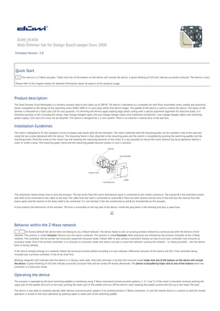
- 1. DUW_05458 Wall-Dimmer-Set for Design Busch-Jaeger Duro 2000 Firmware Version : 1.0 Quick Start A This device is a Z-Wave actuator. Triple click one of the buttons on the device will include the device. A green blinking of LED will indicate successful inclusion. The device is excluded by tri Please refer to the chapters below for detailed information about all aspects of the products usage. Product description The Duwi Dimmer Flush Mountable is a wireless actuator able to dim lights up to 300 W. The device is delivered as a complete set with flush mountable insert, paddle and mounting frame compatible to the design of the switching series DURO 2000 SI in color pearl white from Busch-Jaeger. The paddle of the device is used to control the device. The status of the dimmer is indicated on a dual color LED for test purposes. For dimming the devices apply leading edge phase cutting with a special alignment algorithm for inductive loads. It is therefore possible to dim incandescent lamps, high voltage halogen lights and low voltage halogen lights with traditional transformer. Low voltage halogen lights with switching power supply, LEDs and CFLs must not be attached. This device is designed for a 2 wire system. There is no need for a neutral wire in the wall box. Installation Guidelines The insert is designed to fit into standard circular European wall boxes with 60 mm diameter. The insert combined with the mounting plate can be screwed in top of the wall box using the two screws delivered with the device. The mounting frame is then attached to the mounting plate and the switch is completed by pushing the switching paddle into the mounting frame. Mind the arrow on the inserts top side showing the mounting direction of the insert. It is also possible to mount the insert without any local operation behind a cover or inside a lamp. The mounting plate, frame and the switching paddle become useless in such a scenario. The schematics below shows how to wire the actuator. The hot wired from the mains distribution panel is connected to the inserts contacts L. The contact S is the switched contact and need to be connected to the cable to the load. The cable from the load is connected to neutral N. If there are both neutral and hot wire in the wall box the neutral from the mains panel and the neutral to the lamp need to be connected. It is not harmful if the two connections L and S are mismatched on the actuator. A fuse protects the electronics of the actuator. The fuse is accessible on the top side of the device. Inside the plug there is the working fuse plus a spare fuse. Behavior within the Z-Wave network I On factory default the device does not belong to any Z-Wave network. The device needs to join an existing wireless network to communicate with the devices of this network. This process is called Inclusion. Devices can also leave a network. This process is called Exclusion. Both processes are initiated by the primary controller of the Z-Wave network. This controller will be turned into exclusion respective inclusion mode. Please refer to your primary controllers manual on how to turn your controller into inclusion or exclusion mode. Only if the primary controller is in inclusion or exclusion mode, this device can join or leave the network. Leaving the network - i.e. being excluded - sets the device back to factory default. If the device already belongs to a network, follow the exclusion process before including it in your network. Otherwise inclusion of this device will fail. If the controller being included was a primary controller, it has to be reset first. Blinking red/green LED indicates that the device is in factory reset state. Once the controller is turned into inclusion mode triple click one of the buttons on the device will include the device. A green blinking of LED will indicate successful inclusion that will be turned off shortly afterwards. The device is excluded by triple click to one of the buttons when the controller is in exclusion mode. Operating the device The actuator is operated by the local switching paddles or wirelessly using Z-Wave commands (communication patterns 1, 4, 5 and 7). If the insert is mounted correctly pushing the upper part of the paddle will turn on the load; pushing the lower part of the paddle will turn off the electric load. Keeping the paddle pushed will dim up or dim down the load. The device is also able to remotely operate other devices (communication pattern 5) by sending wireless Z-Wave commands. In case the remote device is a switch as well the remote operation is similar to the local operation by pushing upper to lower part of the switching paddle.
- 2. Child Protection The device can be turn into a child protection mode. In this mode all local operation is disabled. The child protection mode MUST be turned on wirelessly. However in protected by sequence mode it is possible to unlock the device for local operation with a triple click. The unlock state will last for 5 seconds. LED Control Red and green blinking continuously: Device is not included in a Z-Wave network Red lights up for 3 seconds: Device was not included/excluded after being put into learn mode by triple press of up/down button Green lights up for 3 seconds: The inclusion/exclusion was successful or new association was saved successfully Green or no light: depending on settings of configuration parameter for LED control Associations A Z-Wave devices control other Z-Wave devices. The relationship between one device controlling another device is called association. In order to control a different device, the controlling device needs to maintain a list of devices that will receive controlling commands. These lists are called association groups and they are always related to certain events (e.g. button pressed, sensor triggers, ...). In case the event happens all devices stored in the respective association group will receive a common wireless command. Association Groups: 1 Basic On/Off Group (max. nodes in group: 5) Technical Data Power Supply 230V ~50-60 Hz Attachable Loads up to 300 W resistive load or up to 300 VA inductive load Fuse Type: T 1.25 A H (Load 1.25 Ampere, high shutdown capacity), D: 5 mm, L: 20 mm IP Rating IP 20 Frequency 868.42 MHz (SRD Band) Wireless Range up to 100 m outside, on average up to 20 m inside buildings Explorer Frame Support No SDK 5.02 pl1 Device Type Slave with routing capabilities Generic Device Class Multilevel Switch Specific Device Class Multilevel Power Switch Routing Yes FLiRS No Firmware Version 1.0 (c) 2012 Z-Wave Europe GmbH, Goldbachstr. 13, 09337 Hohenstein-Ernstthal, Germany, All rights reserved, www.zwaveeurope.com