1. 60
3.1 Introduction
The vapour absorption refrigeration system is one of the oldest method of
producing refrigerating effect. The principle of vapour absorption was first
discovered by Michael Faraday in 1824 while performing a set of experiments to
liquify certain gases. The first vapour absorption refrigeration machine was
developed by a French scientist Ferdinand Carre in 1860. This system may be used in
both the domestic and large industrial refrigerating plants. The refrigerant,
commonly used in a vapour absorption system, is ammonia.
The vapour absorption system uses heat energy, instead of mechanical
energy as in vapour compression systems, in order to change the conditions of the
refrigerant required for the operation of the refrigeration cycle. We have discussed in
the previous chapters that the function of a compressor, in a vapour compression
system, is to withdraw the vapour refrigerant from the evaporator. It then raises its
temperature and pressure higher than the cooling agent in the condenser so that the
higher pressure vapours can reject heat in the condenser. The liquid refrigerant
leaving the condenser is now ready to expand to the evaporator conditions again.
In the vapour absorption system, the compressor is replaced by an absorber,
a pump, a generator and a pressure reducing valve. These components in vapour
absorption system perform the same function as that of a compressor in vapour
compression system. In this system, the vapour refrigerant from the evaporator is
drawn into an absorber where it is absorbed by the weak solution of the refrigerant
forming a strong solution. This strong solution is pumped to the generator where it is
heated by some external source. During the heating process, the vapour refrigerant is
driven off by the solution and enters into the condenser where it is liquefied. The
liquid refrigerant then flows into the evaporator and thus the cycle is completed.
2. 61
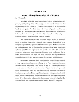
3.2 Simple Vapour Absorption System -
The simple vapour absorption system, as shown in Fig. 3.1, consists of an
absorber, a pump, a generator and a pressure reducing valve to replace the
compressor of vapour compression system. The other components of the system are
condenser, receiver, expansion valve and evaporator as in the vapour compression
system.
Fig 3.1 Simple vapour absorbtion system
. In this system, the low pressure ammonia vapour leaving the evaporator
enters the absorber where it is absorbed by the cold water in the absorber. The water
has the ability to absorb very large quantities of ammonia vapour and the solution
thus formed, is known as aqua-ammonia. The absorption of ammonia vapour in
water lowers the pressure in the absorber which in turn draws more ammonia vapour
from the evaporator and thus raises the temperature of solution. Some form of
cooling arrangement (usually water cooling) is employed in the absorber to remove
the heat of solution evolved there. This is necessary in order to increase the
absorption capacity of water, because at higher temperature water absorbs less
ammonia vapour. The strong solution thus formed in the absorber is pumped to the
generator by the liquid pump. The pump increases the pressure of the solution upto
10 bar.
3. 62
The *strong solution of ammonia in the generator is heated by some external
source such as gas or steam. During the heating process, the ammonia vapour is
driven off the solution at high pressure leaving behind the hot weak ammonia
solution in the generator. This weak ammonia solution flows back to the absorber at
low pressure after passing through the pressure reducing valve. The high pressure
ammonia vapour from the generator is condensed in the condenser to a high pressure
liquid ammonia. This liquid ammonia is passed to the expansion valve through the
receiver and then to the evaporator. This completes the simple vapour absorption
cycle.
3.3 actical Vapour Absorption System
The simple absorption system as discussed in the previous article is not very
economical. In order to make the system more practical, it is fitted with an analyser,
a rectifier and two heat exchangers as shown in Fig. 3.2. These accessories help to
improve the performance and working of the plant, as discussed below :-
Fig. 3.2. Practical vapour absorption system.
4. 63
1. Analyser. When ammonia is vaporised in the generator, some water is
also vaporised and will flow into the condenser along with the ammonia vapours in
the simple system. If these unwanted water particles are not removed before entering
into the condenser, they will enter into the expansion valve where they freeze and
choke the pipe line. In order to remove these unwanted particles flowing to the
condenser, an analyser is used. The analyser may be built as an integral part of the
generator or made as a separate piece of equipment. It consists of a series of trays
mounted above the generator. The strong solution from the absorber and the aqua
from the rectifier are introduced at the top of the analyser and flow downward over
the trays and into the generator. In this way, considerable liquid surface area is
exposed to the vapour rising from the generator. The vapour is cooled and most of
the water vapour condenses, so that mainly ammonia vapour leaves the top of the
analyser. Since the aqua is heated by the vapour, less external heat is required in the
generator.
2. Rectifier. In case the water vapours are not completely removed in the
analyser, a closed type vapour cooler called rectifier (also known as dehydrator) is
used. It is generally water cooled and may be of the double pipe, shell and coil or
shell and tube type. Its function is to cool further the ammonia vapours leaving the
analyser so that the remaining water vapours are condensed. Thus, only dry or
anhydrous ammonia vapours flow to the condenser. The condensate from the
rectifier is returned to the top of the analyser by a drip return pipe.
3. Heat exchangers. The heat exchanger provided between the pump and the
generator is used to cool the weak hot solution returning from the generator to the
absorber. The heat removed from the weak solution raises the temperature of the
strong solution leaving the pump and going to analyser and generator. This operation
reduces the heat supplied to the generator and the amount of cooling required for the
absorber. Thus the economy of the plant increases.
The heat exchanger provided between the condenser and the evaporator may
also be called liquid sub-cooler. In this heat exchanger, the liquid refrigerant leaving
the condenser is sub- cooled by the low temperature ammonia vapour from the
5. 64
evaporator as shown in Fig. 7.2. This sub-cooled liquid is now passed to the
expansion valve and then to the evaporator.
In this system, the net refrigerating effect is the heat absorbed by the
refrigerant in the evaporator. The total energy supplied to the system is the sum of
work done by the pump and the heat supplied in the generator. Therefore, the
coefficient of performance of the system is given by
C.O.P. =
Heat absorbed in evaporator
Work done by pump + Heat supplied in generator
3.4 Advantages of Vapour Absorption Refrigeration System over Vapour
Compression Refrigeration System
Following are the advantages of vapour absorption system over vapour
compression system:
1. In the vapour absorption system, the only moving part of the entire
system is a pump which has a small motor. Thus, the operation of this system is
essentially quiet and is subjected to little wear.
The vapour compression system of the same capacity has more wear, tear
and noise due to moving parts of the compressor.
2. The vapour absorption system uses heat energy to change the condition of
the refrigerant from the evaporator. The vapour compression system uses mechanical
energy to change the condition of the refrigerant from the evaporator.
3. The vapour absorption systems are usually designed to use steam, either
at high pressure or low pressure. The exhaust steam from furnaces and solar energy
may also be used. Thus this system can be used where the electric power is difficult
to obtain or is very expensive.
4. The vapour absorption systems can operate at reduced evaporator
pressure and temperature by increasing the steam pressure to the generator, with little
decrease in capacity. But the capacity of vapour compression system drops rapidly
with lowered evaporator pressure.
6. 65
5. The load variations does not effect the performance of a vapour
absorption system. The load variations are met by controlling the quantity of aqua
circulated and the quantity of steam supplied to the generator.
The performance of a vapour compression system at partial loads is poor.
6. In the vapour absorption system, the liquid refrigerant leaving the
evaporator has no bad effect on the system except that of reducing the refrigerating
effect. In the vapour compression system, it is essential to superheat the vapour
refrigerant leaving the evaporator so that no liquid may enter the compressor.
7. The vapour absorption systems can be built in capacities well above 1000
tonnes of refrigeration each which is the largest size for single compressor units.
8. The space requirements and automatic control requirements favour the
absorption system more and more as the desired evaporator temperature drops.
3.5 Coefficient of Performance of an Ideal Vapour Absorption
Refrigeration System
We have discussed earlier that in an ideal vapour absorption refrigeration
system,
(a) the heat (QG) is given to the refrigerant in the generator,
(b) the heat (Qc) is discharged to the atmosphere or cooling water from the
condenser and absorber.
(c) the heat (QE) is absorbed by the refrigerant in the evaporator, and
(d) the heat (Qp) is added to the refrigerant due to pump work.
Neglecting the heat due to pump work (Qp), we have according to First Law
of Thermodynamics,
C G EQ Q Q= + ... (i)
Let TG = Temperature at which heat (QG) is given to the generator,
7. 66
Tc = Temperature at which heat (QC) is discharged to atmosphere or cooling
water from the condenser and absorber, and
TE = Temperature at which heat (QE) is absorbed in the evaporator.
Since the vapour absorption system can be considered as a perfectly
reversible system, therefore the initial entropy of the system must be equal to the
entropy of the system after the change in its condition.
∴ G CE
G E C
Q QQ
T T T
+ = ...(ii)
= G E
C
Q Q
T
+
... [ From equation (i) ]
or G G E E
G C C E
Q Q Q Q
T T T T
− = −
C G E C
G E
G C C E
T T T T
Q Q
T T T T
+ −
=
× ×
QG = E C G C
E
C E C G
T T T T
Q
T T T T
− ×
× −
= C E G C
E
C E G C
T T T T
Q
T T T T
− ×
× −
= C E G
E
E G C
T T T
Q
T T T
−
−
... (iii)
Maximum coefficient of performance of the system is given by
(C.O.P.)max = E
G
Q
Q
= E
C E G
E
E G C
Q
T T T
Q
T T T
−
−
= G CE
C E G
T TT
T T T
−
−
...(iv)
It may noted that,
8. 67
I. The expression E
C E
T
T T−
is the C.O.P. of a Carnot refrigerator working
between the temperature limits of T E and T C.
2. The expression G C
G
T T
T
−
is the efficiency of a Carnot engine working
between the temperature limits of TG and TC.
Thus an ideal vapour absorption refrigeration system may be regarded as a
combination of a Carnot engine and a Carnot refrigerator. The maximum C.O.P. may
be written as
(C.O.P.)max = (C.O.P)carnot × ηcarnot
In case the heat is discharged at different temperatures in condenser and
absorber, then
(C.O.P.)max = G CE
C E G
T TT
T T T
−
−
where TA= Temperature at which heat is discharged in the absorber.
Example 3.1. In a vapour absorption refrigeration system, heating, cooling
and refrigeration takes place at the temperatures of 100o
C, 20o
C and _5° C
respectively. Find the maximum C.O.P. of the system.
Solution. Given: TG = 100o
C = 100 + 273 = 373 K ; Tc = 20o
C = 20 + 273
= 293 K ; T E = - 5° C = - 5 + 273 = 268 K
We know that maximum C.O.P. of the system
= G CE
C E G
T TT 268 373 293
T T T 293 268 373
− −
=
− −
= 2.3 Ans.
Example 3.2. In an absorption type refrigerator, the heat is supplied to NH3
generator by condensing steam at 2 bar and 90% dry. The temperature in the
refrigerator is to be maintained at - 5° C. Find the maximum C.O.P. possible.
9. 68
If the refrigeration load is 20 tonnes and actual C.O.P. is 10% of the
maximum C.O.P ., find the mass of steam required per hour. Take temperature of the
atmosphere as 30o
C.
Solution. Given: p = 2 bar; x = 90% = 0.9; TE = -5°C = -5 + 273 = 268 K ;
Q = 20 TR; Actual C.O.P. = 70% of maximum C.O.P. ; TC = 30° C = 30 + 273 = 303
K
Maximum C.O.P.
From steam tables, we find that the saturation temperature of steam at a
pressure of 2 bar is
TG = 120.2° C = 120.2 + 273 = 393.2 K
We know that maximum C.O.P.
= G CE
C E G
T TT
T T T
−
−
=
268 393 303
303 268 393.2
−
−
= 1.756 Ans.
Mass of steam required per hour
We know that actual C.O.P.
= 70% of maximum C.O.P. = 0.7 × 1.756 = 1.229
∴Actual heat supplied
=
Refrigeration load
Actual C.O.P.
=
20 210
1.229
×
= 3417.4 kJ/min
Assuming that only latent heat of steam is used for heating purposes,
therefore from steam tables, the latent heat of steam at 2 bar is
hfg = 2201.6 kJ/kg
∴ Mass of steam required per hour
=
fg
Actual heat supplied
x × h
=
3417.4
2201.6
= 1.552 kg/min= 93.12 kg/h Ans.
10. 69
3.6 Domestic Electrolux (Ammonia Hydrogen) Refrigerator
The domestic absorption type refrigerator was invented by two Swedish
engineers Carl Munters and Baltzer Von Platan in 1925 while they were studying for
their under-graduate course of Royal Institute of Technology in Stockholm. The idea
was first developed by the ‘Electrolux Company’ of Luton, England.
Fig. 3.3. Domestic electrolux type refrigerator.
This type of refrigerator is also called three-fluids absorption system. The
main purpose of this system is to eliminate the pump so that in the absence of
moving parts. the machine becomes noise-less. The three fluids used in this sytem
are ammonia, hydrogen and water. The ammonia is used as a refrigerant because it
possesses most of the desirable properties. It is toxic. but due to absence of moving
parts, there is very little changes for the leakage and the total amount of refrigeration
used is small. The hydrogen being the lightest gas. is used to increase the rate of
evaporation of the liquid ammonia passing through the evaporator. The hydrogen is
also non-corrosive and insoluble in water. This is used in the low-pressure side of the
system. The water is used as a solvent because it has the ability to absorb ammonia
readily. The principle of operation of a domestic electolux type refrigerator. as
shown in Fig. 3.3. is discussed below:
The strong ammonia solution from the absorber through heat exchanger is
heated in the generator by applying heat from an external source usually a gas
11. 70
burner. During this heating process, ammonia vapours are removed from the solution
and passed to the condenser. A rectifirer or a water separator fitted before the
condenser removes water vapour carried with the ammonia vapours. so that dry
ammonia vapours are supplied to the condenser. These water vapours,.
f not
removed, they will enter into the evaporator causing freezing and choking of the
machine . The hot weak solution left behind in the generator flow to the absorber
through the heat excl anger. This hot weak solution while passing through the
exchanger is cooled. The heat removed by the weak solution is utilised in raising the
temperature of strong solution passing through the heat exchanger. In this way, the
absorption is accelerated and the improvement in the performance of a plant is
achieved.
The ammonia vapours in the condenser are condensed by using external
cooling source. The liquid refrigerant leaving the condenser flows under gravity to
the evaporator where it meets the hydrogen gas. The hydrogen gas which is being fed
to the evaporator permit the liquid ammonia to evaporate at a low pressure and
temperature according to Dalton's principle. During the process of evaporation, the
ammonia absorbs latent heat from the refrigerated space and thus produces cooling
effect.
The mixture of ammonia vapour and hydrogen is passed to the absorber
where ammonia is absorbed in water while the hydrogen rises to the top and flows
hack to the evaporator. This completes the cycle. The coefficient of performance of
this refrigerator is given by :
C.O.P. =
Heat absorbed in the evaporator
Heat supplied in the generator
Notes: 1. The hydrogen gas only circulates from the absorber to the
evaporator and back.
2. The whole cycle is carried out entirely by gravity flow of the refrigerant.
3. It can not be used for industrial purposes as the C.O.P. of the system is
very low.
12. 71
3.7 Lithium Bromide Absorption Refrigeration System
The lithium-bromide absorption refrigeration system uses a solution of
lithium bromide in water. In this system, the *water is being used as a refrigerant
whereas lithium bromide, which is a highly hydroscopic salt, as an absorbent. The
lithium bromide solution has a strong affinity for water vapour because of its very
low vapour pressure. Since lithium bromide solution is corrosive, therefore inhibitors
should be added in order to protect the metal parts of the system against corrosion.
Lithium chromate is often uged as a corrosion inhibitor. This system is very popular
for air conditioning in which low refrigeration temperatures (not below 0° C)** are
required.
Fig. 3.4 shows a lithium bromide vapour absorption system. In this system.
the absorber and the evaporator are placed in one shell which operates at the same
low pressure of the system. The generator and condenser are placed in another shell
which operates at the same high pressure of the system. The principle of operation of
this system is discussed below :
The water for air-conditioning coils or process requirements is chilled as it
is pumped through the chilled-water tubes in.the evaporator by giving up heat to the
refrigerant water sprayed over the tubes. Since the pressure inside the evaporator is
maintained very low, therefore, the refrigerant water evaporates. The water vapours
thus formed will be absorbed by the strong lithium-bromide solution which is
sprayed in the absorber. In absorbing the water vapour, the lithium bromide solution
helps in maintaining very low pressure (high vacuum) needed in the evaporator, and
the solution becomes weak. This weak solution is pumped by a pump to the
generator where it is heated up by using steam or hot water in the heating coils. A
portion of water is evaporated by the heat and the solution now becomes more
strong. This strong solution is passed through the heat exchanger and then sprayed in
the absorber as discussed above. The weak solution of lithium bromide from the
absorber to the generator is also passed through the heat exchanger. This weak
solution gets heat from the strong solution in the heat exchanger, thus reducing the
quantity of steam required to heat the weak solution in the generator.
13. 72
Fig. 3.4. Lithium-Bromide absorption refrigeration system.
The refrigerant water vapours formed in the generator due to heating of
solution are passed to the condenser where they are cooled and condensed by the
cooling water flowing through the condenser water tubes. The cooling water for
condensing is pumped from the cooling water pond or tower. This cooling water first
enters the absorber where it takes away the heat of condensation and dilution. The
condensate from the condenser is supplied to the evaporator to compensate the water
vapour formed in the evaporator. The pressure reducing valve reduces the pressure of
condensate from the condenser pressure to the evaporator pressure. The cooled water
from the evaporator is pumped and sprayed in the evaporator in order to cool the
water for air conditioning flowing through the chilled tubes. This completes the
cycle.
Note: The pressure difference between the generator and the absorber and
the gravity due to the height difference of the two shells is utilised to create the
pressure for the spray.
14. 73
3.8 Refrigerats
The refrigerant is a heat carrying medium which during their cycle (i.e.
compression, condensation, expansion and evaporation) in the refrigeration system
absorb heat from a low temperature system and discard the heat so absorbed to a
higher temperature system.
The natural ice and a mixture of ice and salt were the first refrigerants. In
1834, ether, ammonia, sulphur dioxide, methyl chloride and carbon dioxide came
into use as refrigerants in compression cycle refrigeration machines. Most of the
early refrigerant materials have been discarded for safety reasons or for lack of
chemical or thermal stability. In the present days, many new refrigerants including
halo-carbon compounds, hydro-carbon compounds are used for air conditioning and
refrigeration applications.
The suitability of a refrigerant for a certain application is determined by its
physical, thermodynamic, chemical properties and by various practical factors. There
is no one refrigerant which can be used for all types of applications i.e., there is no
ideal refrigerant. If one refrigerant has certain good advantages, it will have some
disadvantages also. Hence, a refrigerant is chosen which has greater advantages and
less disadvantages.
3.9 Desirable Properties of an Ideal Refrigerant
We have discussed above that there is no ideal refrigerant. A refrigerant is
said to be ideal if it has all of the following properties:
I. Low boiling point,
2. High critical temperature,
3. High latent heat of vaporisation.
4. Low specific heat of liquid.
5. Low specific volume of vapour,
6. Non-corrosive to metal,
15. 74
7. Non-flammable and non-explosive,
8. Non-toxic,
9. Low cost,
10. Easy to liquify at moderate pressure and temperature,
11. Easy of locating leaks by odour or suitable indicator, and
12. Mixes well with oil.
The standard comparison of refrigerants, as used in the refrigeration
industry, is based on an evaporating temperature of - 15° C and a condensing
temperature of + 30° C.
3.10 Classification of Refrigerants
The refrigerants may, broadly, be classified into the following two groups:
1. Primary refrigerants, and 2. Secondary refrigerants.
The refrigerants which directly take part in the refrigeration system are
called primary refrigerants whereas the refrigerants which are first cooled by
primary refrigerants and then used for cooling purposes are known as secondary
refrigerants.
The primary refrigerants are further classified into the following four
groups:
I. Halo-carbon refrigerants,
2. Azeotrope refrigerants,
3. Inorganic refrigerants. and
4. Hydro-carbon refrigerants.
These above mentioned refrigerants are discussed, in detail, in the following pages.
8.4 Halo-carbon Refrigerants
The American Society of Heating, Refrigeration and Air-conditioning
Engineers (ASHARAE) identifies 42 halo-carbon compounds as refrigerants, but
16. 75
only a few of them are commonly used. The following table gives some of the
commonly used halo-carbon refrigerants:
Table 3.1. Commonly used halo-carbon refrigerants
Refigerant number Chemical name Chemical formula
R-11 Trichloromonofluoromethane 3CCl F
R-12 Dichlorodifluoromethane 2 2CCl F
R-13 Monochlorotrifluoromethane 3CClF
R-14 Carbontetrafluoride 4CF
R-21 Dichloromonofluoromethane 2CHCl F
R-22 Monochlorodifluoromethane 2CHClF
R-30 Methylene chloride 2 2CH Cl
R-40 Methyl chloride 3CH Cl
R-100 Ethyl chloride 2 5C H Cl
R-113 Trichlorotrifluorothane 2 2CCl FCCF
R-114 Dichlorotetrafluoroethane 2 2CClF CCIF
R-115 Monochloropentafluoroethane 2 3CClF CF
17. 76
The halo-carbon compounds are all synthetically produced and were
developed as Freon family of refrigerants. Freon is a registered trade mark of E.I. Du
Pont de Nemours and Co., America. Most of the halo-carbon refrigerants, are now
available from other manufacturers under various trade names such as Genetron,
Isotron etc. The first of the halo-carbon refrigerant i.e. R-12 was developed in 1930
by Thomas Midgley. The various halo-carbon refrigerants mentioned above are now
discussed, in detail, as below:
I. R-11, Trichloromonofluoromethane (CCl3F). The R-11 is a synthetic
chemical product which can be used as a refrigerant. It is stable, non-flammable and
non-toxic. It is considered to be a low-pressure refrigerant. It has a low side pressure
of 0.202 bar at -15°C and high side pressure of 1.2606 bar at 30°C. The latent heat at
-15°C is 195 kJ/kg. The boiling point at atmospheric pressure is 23.77°C. Due to its
low operating pressures, this refrigerant is exclusively used in large centrifugal
compressor systems of 200 TR and above. The leaks may be detected by using a
soap solution, a halide torch or by using an electronic detector.
R-11 is often used by service technicians as a flushing agent for cleaning the
internal parts of a refrigerator compressor when overhauling systems. It is useful
after a system had a motor burn out or after it has a great deal of moisture in the
system. By flushing moisture from the system with R-11, evacuation time is
shortened. R-11 is one of the safest cleaning solvent that can be used for this
purpose. The cylinder colour code for R-11 is orange.
2. R-12, Dichlorodifluoromethane (CCl2F2). The R-12 is a very popular
refrigerant. It is a colourless, almost odourless liquid with boiling point of - 29°C at
atmospheric pressure. It is non-toxic, non-corrosive, non-irritating and non-
flammable. It has a relatively low latent heat value which is an advantage in small
refrigerating machines. The large amount of refrigerant circulated will permit the use
of less sensitive and more positive operating and regulating mechanisms. It operates
at a low but positive head and back pressure and with a good volumetric efficiency.
This refrigerant is used in many different types of industrial and commercial
applications such as refrigerators, freezers, water coolers, room and window air
18. 77
conditioning units etc. Its principal use is found in reciprocating and rotary
compressors, but its use in centrifugal compressors for large commercial air
conditioning is increasing.
R-12 has a pressure of 0.82 bar at - 15°C and a pressure of 6.4 bar at 30°C.
The latent heat of R-12 at - 15°C is 159 kJ/kg. The leak may be detected by soap
solution, halide torch or an electronic leak detector. Water is only slightly soluble in
R- 12. At - 18°C, it will hold six parts per million by mass. The solution formed is
very slightly corrosive to any of the common metals used in refrigerator construction.
The addition of mineral oil to the refrigerant has no effect upon the corrosive action.
R-12 is more critical as to its moisture content when compared to R-22 and
R-502. It is soluble in oil down to - 68°C. The oil will begin to separate at this
temperature and due to its lightness than the refrigerant, it will collect on the surface
of the liquid refrigerant. The refrigerant is available in a variety of cylinder sizes and
the cylinder colour code is white.
3. R-13, Monochlorotrifluoromethane (CClF3). The R-13 has a boiling
temperature of - 81.4°C at atmospheric pressure and a critical temperature of +
28.8°C. This refrigerant is used for the low temperature side of cascade systems. It is
suitable with reciprocating compressors.
4. R-14, Carbontetraf1uoride (CF4). The R-14 has a boiling temperature of -
128°C at atmospheric pressure and critical temperature of - 45.5°C. It serves as an
ultra-low temperature refrigerant for use in cascade systems.
5. R-21, Dichloromonof1uoromethane (CHCl2F). The R-2l has a boiling
temperature of + 9°C at atmospheric pressure. It has found its principal use in
centrifugal compressor systems for relatively high temperature refrigeration
requirements.
6. R-22, Monochlorodifluoromethane (CHClF2). The R-22 is a man-made
refrigerant developed for refrigeration installations that need a low evaporating
temperature, as in fast freezing units which maintain a temperature of - 29°C to -
40°C. It has also been successfully used in air conditioning units and in household
refrigerators. It is used with reciprocating and centrifugal compressors. It is not
19. 78
necessary to use R-22 at below atmospheric pressures in order to obtain the low
temperatures.
The boiling point of R-22 is - 41°C at atmospheric pressure. It has a latent
heat of 216.5 kJ/kg at - 15°C. The normal head pressure at 30°C is 10.88 bar. This
refrigerant is stable and is non-toxic, non-corrosive, non-irritating and non-
flammable. The evaporator pressure of this refrigerant at - 15o
C is 1.92 bar. Since
water mixes better with R-22 than R- 12 by a ratio of 3 to I, therefore driers
(dessicants) should be used to remove most of the moisture to keep water to a
minimum. This refrigerant has good solubility in oil down to - 9°C. However, the oil
remains fluid enough to flow down the suction line at temperatures as low as - 40o
C.
The oil will begin to separate at this point. Since oil is lighter, therefore it will collect
on the surface of the liquid refrigerant. The leaks may be detected with a soap
solution, a halide torch or with an electronic leak detector. The cylinder colour code
for R-22 is green.
7. R-30, Methylene Chloride (CH2Cl2). The R-30 is a clear, water-white
liquid with a sweet, non-irritating odour similar to that of chloroform. It has a boiling
point of 39.8°C at atmospheric pressure. It is non-flammable, non-explosive and non-
toxic. Due to its high boiling point, this refrigerant may be stored in closed cans
instead of in compressed gas cylinders. The high and low sides of refrigeration
system using R-30 operate under a vacuum. Since the volume of vapour at suction
conditions is very high, therefore the use of R-30 is restricted to rotary or centrifugal
compressors. This refrigerant was extensively used for air conditioning of theatres,
auditoriums, and office buildings. Now-a-days, the refrigerant R-11 is used in place
of R-30.
In order to detect leaks in a system using R-30, the pressure must be
increased above atmosphere. A halide torch is used for detecting leaks.
8. R-40, Methyl-chloride (CH3Cl). The R-40 is a colourless liquid with a
faint, sweet, and non-irritating odour. Its boiling point at atmospheric pressure is -
23.7o
C and the usual condenser pressure is 5 to 6.8 bar. The latent heat of
vaporisation at - 15o
C is 423.5 kJ/kg. It is flammable and explosive when mixed with
air in concentrations from 8.1 to 17.2 percent. This refrigerant is non-corrosive in its
20. 79
pure state, but it becomes corrosive in the presence of moisture. Aluminium. zinc and
magnesium alloys should never be used with this refrigerant as they will corrode
considerably and pollute the lubricating oil. Since the refrigerant R-40 is a solvent
for many materials used in ordinary refrigeration compressors, therefore rubber and
gaskets containing rubber should never be used. However, synthetic rubber is not
affected by R-40. Thus metallic or asbestos-fibre gaskets containing insoluble
binders should be used. The mineral oils are soluble in this refrigerant to a small
extent.
This refrigerant has been used in domestic units with both reciporating and
rotary compressors and in commercial units with reciporcating compressors upto
approximately 10 TR capacity. The leaks with RAO may be detected by soap
solution or electronic leak detector.
9. R-100. Ethyl Chloride (C2H5Cl). The refrigerant R-100 is a colourless
liquid and in many respects it is similar to R-40 (Methyl chloride) but with low
operating pressures. It has a boiling point of 13.lo
C at atmospheric pressure. It is both
toxic and flammable. Due to its low operating pressure, it is not used in refrigerating
equipment.
10. R-113. Trichlorotrifluoroethane (CCl2FCClF2, or C2Cl3F3). The R-113
has a boiling point of 47 .6° C at atmospheric pressure. It is used in commercial and
industrial air- conditioning with centrifugal compressor systems. Since this
refrigerant has the advantage of remaining liquid at room temperatures and pressures,
therefore it can be carried in sealed tins rather than cylinders.
11. R-114, Dichlorotetrafluoroethane, (CClF2CClF2 or C2Cl2F4). The R-
114 has a boiling point of 3.6°C at atmospheric pressure. At - 15°C, it evaporates at a
pressure of 0.54 bar and at + 30°C it condenses at a pressure of 1.5 bar. Its latent heat
of vaporisation at - 15°C is 143 kJ/kg. It is non-toxic, non-explosive and non
corrosive even in the presence of water. It is used in fractional power household
refrigerating systems and drinking water coolers employing rotary-vane type
compressors.
Note: Out of all the halo-carbon refrigerants, discussed above, only R-11,
R-12 and R-22 are the most important and are extensively used now -a-days.
21. 80
3.11 Azeotrope Refrigerants
The term 'azeotrope'refers to a stable mixture of refrigerants whose vapour
and liquid phases retain identical compositions over a wide range of temperatures.
However, these mixtures, usually, have properties that differ from either of their
components. Some of the azeotropes are given in the following table:
Table 3.2. Azeotrope refrigerants.
Refrigerant number Azeotropic refrigerants Chemical formula
R-500 7.38% R-12 and 26.2% R-
152
2 2 3 2CCl F /CH CHF
R-502 48.8% R-22 and 51.2% R-
115
2 2 2 3CHClF /CClF CCIF CF
R-503 40.1% R-23 and 59.9% R-13 3 3CHF /CCIF
R-504 48.2% R-32 and 51.8% R-
115
2 2 2 3CH F /CCIF CF
These refrigerant are discussed, in detail, as below:
1. R-500. The R-500 is an azeotropic mixture of 73.8% R-12 ( CCl2F2) and
26.2% of R-152 (CH3CHF2). It is non flammable, low in toxicity and non-corrosive.
It is used in both industrial and commercial applications but only in systems with
reciprocating compressors. It has a fairly constant vapour pressure temperature curve
which is different from the vaporizing curves for either R-152 a or R- 12.
This refrigerant offers about 20% greater refrigerating capacity than R-12
for the same size of motor when used for the same purpose. The evaporator pressure
of this refrigerant is 1.37 bar at - 15°C and its condensing pressure is 7.78 bar at
30°C. It has a boiling point of - 33°C at atmospheric pressure. Its latent heat at -
15°C is 192 kJ/kg. It can be used whenever a higher capacity than that obtained with
R-12 is needed. The solubility of water in R-500 is highly critical. It has fairly high
solubility with oil. The leakage may be detected by using soap solution, a halide
22. 81
torch, an electronic leak detector or a coloured tracing agent. The servicing
refrigerators using this refrigerant does not present any unusual problem. Water is
quite soluble in this refrigerant. It is necessary to keep moisture out of the system by
careful dehydration and by using driers. The cylinder colour code for this refrigerant
is yellow.
2. R-502. The R-502 is an azeotropic mixture of 48.8% R-22 (CHClF2) and
51.2% of R-15 (CClF2CF3). It is a non flammable, non- corrosive, practically non-
toxic liquid. It is a good refrigerant for obtaining medium and low temperatures. It is
suitable where temperatures from - 18°C to - 51°C are needed. It is often used in
frozen food lockers, frozen food processing plants, frozen food display cases and in
storage units for frozen foods and ice-cream. It is only used with reciprocating
compressors. The boiling point of this refrigerant at atmospheric pressure is - 46° C
Its evaporating pressure at - 15°C is 2.48 bar and the condensing pressure at 30°C is
12.06 bar. Its latent heat at - 29° C is 168.6 kJ/kg.
The R-502 combines many of the good properties of R-12 and R-22. It gives
a machine capacity equal to that of R-22 with just about the condensing temperature
of a system using R-12. Since this refrigerant has a relatively low condensing
pressure and temperature, therefore it increases the life of compressor valves and
other parts. Better lubrication is possible because of the increased viscosity of the oil
at low condensing temperature. It is possible to eliminate liquid injection to cool the
compressor because of the low condensing pressure.
This refrigerant has all the qualities found in other halogenated
(fluorocarbon) refrigerants. It is non-toxic, non-flammable, non- irritating, stable and
non-corrosive. The leaks may be detected by soap solution, halide torch or electronic
leak detector. It will hold 1.5 times more moisture at - 18°C than R-12. It has fair
solubility in oil above 82°C. Below this temperature, the oil tries to separate and
tends to collect on the surface of the liquid refrigerant. However, oil is carried back
to the compressor at temperatures down to - 40°C. Special devices are sometimes
used to return the oil to the compressor. The cylinder colour code for this refrigerant
is orchid.
23. 82
3. R-503. The R-503 is an azeotropic mixture of 40.1 % R-23 (CHF3) and
59.9% of R-13 (CCIF3). This is a non-flammable, non-corrosive, practically non-
toxic liquid. Its boiling temperature at atmospheric pressure is - 88°C which is lower
than either R-23 or R-13. Its evaporating pressure at - 15°C is 17.15 bar. Its critical
temperature is 20o
C and its critical pressure is 41.15 bar. This is a low temperature
refrigerant and good for use in the low state of cascade systems which require
temperatures in the range of -73°C to - 87°C. The latent heat of vaporisation at
atmospheric pressure is 173 kJ/kg.
The leaks in R-503 systems may be detected with the use of soap solution, a
halide torch or an electronic leak detector. This refrigerant will hold more moisture
than some other low temperature refrigerants. It may be noted that all low
temperature applications must have extreme dryness, because any moisture not in
solution with refrigerant is likely to form ice at the refrigerant control devices. The
oil does not circulate well at low temperatures. The cascade and other low
temperature equipments are normally fitted with oil separators and other devices for
returning the oil to the compressor. The cylinder colour code for R-503 is
aquamarine.
4. R-504. The R-504 is an azeotropic mixture of 48.2% R-32 (CH2F2) and
51.8 % R-115 (CClF2CF3). It is non-flammable, non-corrosive and non-toxic. The
boiling temperature at atmospheric pressure is - 57°C. Its evaporating pressure at -
15°C is 5.88 bar and its critical pressure is 48 bar. As with all low temperature
refrigerants, some difficulty may be experienced with the oil circulation. With the
addition to 2 to 5% R-170 (ethane), the oil will be taken into the solution with the
refrigerant and will circulate through the system with it.
The leaks in R-504 systems may be easily detected by using soap solution, a
halide torch or an electronic leak detector. This refrigerant is used in industrial
processes where a low temperature range of - 40°C to - 62°C is desired. The cylinder
colour code for R- 504 is tan.
3.6 Inorganic Refrigerants
The inorganic refrigerants were exclusively used before the introduction of
halocarbon refrigerants. These refrigerants are still in use due to their inherent
24. 83
thermodynamic and physical properties. The various inorganic refrigerants are given
in the following table:
Table 3.3. Inorganic refrigerants.
Refrigerant number Chemical name Chemical formula
R-717 Ammonia NH3
R-729 Air _
R-744 Carbon dioxide CO2
R-764 Sulphur dioxide SO2
R-118 Water H2O
These refrigerants are discussed, in detail, as below:
I. R-717 (Ammonia). The R-717, i.e. ammonia (NH3) is one of the oldest
and most widely used of all the refrigerants. Its greatest application is found in large
and commercial reciprocating compression systems where high toxicity is secondary.
It is also widely used in absorption systems. It is a chemical compound of nitrogen
and hydrogen and under ordinary conditions, it is a colourless gas. Its boiling point at
atmospheric pressure is - 33.3°C and its melting point from the solid is - 78°C. The
low boiling point makes it possible to have refrigeration at temperatures considerably
below O°C without using pressures below atmospheric in the evaporator. Its latent
heat of vaporisation at - 15°C is 1315 kJ/kg. Thus, large refrigerating effects are
possible with relatively small sized machinery. The condenser pressure at 30o
C is
10.78 bar. The condensers for R- 717 are usually of water cooled type.
It is a poisonous gas if inhaled in large quantities. In lesser quantities, it is
irritating to the eyes, nose and throat. This refrigerant is somewhat flammable and
when mixed with air in the ratio of 16% to 25% of gas by volume, will form an
explosive mixture. The leaks of this refrigerant may be quickly and easily detected
by the use of burning sulphur candle which in the presence of ammonia forms white
25. 84
fumes of ammonium sulphite. This refrigerant attacks copper and bronze in the
presence of a little moisture but does not corrode iron or steel. It presents no special
problems in connection with lubricant unless extreme temperatures are encountered.
Since the refrigerant R-717 is lighter than oil, therefore, its separation does not create
any problem. The excess oil in the evaporator may be removed by opening a valve in
the bottom of the evaporator. This refrigerant is used in large compression machines
using reciprocating compressors and in many absorption type systems. The use of
this refrigerant is extensively found in cold storage, warehouse plants, ice cream
manufacture, ice manufacture, beer manufacture, food freezing plants etc.
2. R-729 (Air). The dry air is used as a gaseous refrigerant in some
compression systems, particularly in air-craft air conditioning.
3. R-744 (Carbon dioxide). The principal refrigeration use of carbon dioxide
is same as that of dry ice. It is non-toxic, non- irritating and non-flammable. The
boiling point of this refrigerant is so extremely low (- 73.6°C) that at - 15°C, a
pressure of well over 20.7 bar is required to prevent its evaporation. At a condenser
temperature of + 30°C, a pressure of approximately 70 bar is required to liquify the
gas. Its critical temperature is 31°C and triple point is - 56.6°C. Due to its high
operating pressure, the compressor of a carbon dioxide refrigerator unit is very small
even for a comparatively large refrigerating capacity. However, because of its low
efficiency as compared to other common refrigerants, it is seldom used in household
units, but is used in some industrial applications and aboard ships.
4. R-764 (Sulphur dioxide). This refrigerant is produced by the combustion
of sulphur in air. In the former years, it was widely used in household and small
commercial units. The boiling point of sulphur dioxide is - 10°C at atmospheric
pressure. The condensing pressure varies between 4.1 bar and 6.2 bar under normal
operating conditions. The latent heat of sulphur dioxide at - 15°C is 396 kJ/kg. It is a
very stable refrigerant with a high critical temperature and it is non-flammable and
non-explosive. It has a very unpleasant and irritating odour. This refrigerant is not
injurious to food and is used commercially as a ripener and preservative of foods. It
is however, extremely injurious to flowers, plants and shrubbery. The sulphur
dioxide in its pure state is not corrosive, but when there is moisture present, the
26. 85
mixture forms sulphurous acid which is corrosive to steel. Thus it is very important
that the moisture in the refrigerating system be held to a minimum.
The sulphur dioxide does not mix readily with oil. Therefore, oil lighter than
that used with other refrigerants may be used in the compressors. The refrigerant in
the evaporator with oil floating on the top has a tendency to have a higher boiling
point than that corresponding to its pressure. The modern evaporators overcome this
by having the liquid introduced in such a way that the refrigerant is kept agitated
while the unit is in operation. The leaks in the system with sulphur dioxide may be
easily detected by means of soap solution or ammonia swab. A dense white smoke
forms when sulphur doxide and ammonia fumes come in contact.
5. R-118 (Water). The principal refrigeration use of water is as ice. The high
freezing temperature of water limits its use in vapour compression systems. It is used
as the refrigerant vapour in some absorption systems and in systems with steam jet
compressors.
3.12Hydro-carbon Refrigerants
Most of the hydro-carbon refrigerants are successfully used in industrial and
commercial installations. They possess satisfactory thermodynamic properties but are
highly flammable and explosive. The various hydro-carbon refrigerants are given in
the following table:
Table 3.4. Hydro-carbon refrigerants.
Refrigerant number Chemical name Chemical formula
R-170 Ethane 2 6C H
R-290 Propane 3 3C H
R-600 Butane 4 10C H
R-600a Isobutane 4 10C H
27. 86
R-1120 Trichloroethylene 2 4 3C H Cl
R-1130 Dischloroethylene 2 4 2C H Cl
R-1150 Ethylene 2 4C H
R-1270 Propylene 3 6C H
Since the hydro-carbon refrigerants are not commonly used now-a- days.
therefore, they arc not discussed in detail.
3.13 Designation System for Refrigerants
The refrigerants are internationally designated as 'R'followed by certain
numbers such as R-11, R-12, R-114 etc. A refrigerant followed by a two digit
number indicates that a refrigerant is derived from methane base while three digit
number res presents ethane base. The numbers assigned to hydro-carbon and halo-
carbon refrigerants have a special meaning. The first digit on the right is the number
of fluorine (F) atoms in the refrigerant. The second digit from the right is one more
than the number of hydrogen (H) atoms present. The third digit from the right is one
less than the number of carbon (C) atoms, but when this digit is zero, it is omitted.
The general chemical formula for the refrigerant, either for methane or ethane base,
is given as CmHnClpFq, in which
n+ P + q = 2m+ 2
where
m = Number of carbon atoms,
n = Number of hydrogen atoms,
p = Number of chlorine atoms, and q = Number of fluorine atoms.
As discussed above, the number of the refrigerant is given by R (m - l)(n +
l) (q). Let us consider the following refrigerants to find its chemical formula and the
number.
1. Dichloro-tetrafluoro-ethane
28. 87
We see that in this refrigerant
Number of chlorine atoms, p = 2
Number of fluorine atoms, q = 4
and number of hydrogen atoms, n = 0
We know that n + p + q = 2m + 2
0 + 2 + 4 = 2 m + 2
∴m = 2
i.e. Number of carbon atoms = 2
Thus the chemical formula for dichloro-tetrafluoro-ethane becomes C2C12F
4 and the number of refrigerant becomes R(2-1) (0+ 1 )(4) or R-114.
2. Dichloro-difluoro-methane.
We see that in this refrigerant
Number of chlorine atoms, p = 2
Number of fluorine atoms, q = 2
and number of hydrogen atoms, n = 0
We know that n+ p + q = 2m + 2
0 + 2 + 2 = 2m + 2
∴m = 1
i.e. Number of carbon atoms = 1
Thus the chemical formula for dichloro-difluoro-methane becomes CCl2F2
and the number of refrigerant becomes R (1-1) (0 + 1) (2) or R- 012 i.e. R-12.
The inorganic refrigerants are designated by adding 700 to the molecular
mass of the compound. For example, the molecular mass of ammonia is 17, therefore
it is designated by R - (700 + 17) or R-717.
29. 88
3.14Comparison of Refrigerants
There is no such refrigerant (i.e. ideal refrigerant) which can be used under
all operating conditions. The characteristics of some refrigerants make them suitable
for use with reciprocating compressors and other refrigerants lire best suited to
centrifugal or rotary compressors Therefore in order to select a correct refrigerant, it
is necessary that it should satisfy those properties which make it ideal to be used for
the particular application. We shall now discuss the thermodynamic, chemical and
physical properties of some important refrigerants.
3.15 Thermodynamic Properties of Refrigerants
The thermodynamic properties of refrigerants are discussed, in detail, as
follows: 1. Boiling temperature. The boiling temperature of the refrigerant at
atmospheric pressure should be low. If the boiling temperature of the refrigerant is
high at atmospheric pressure, the compressor should be operated at high vacuum.
The high boiling temperature reduces the capacity and operating cost of the system.
The following table shows the boiling temperatures at atmospheric pressure of some
commonly used refrigerants. Table 3.5. Boiling temperatures.
Refrigerant Boiling temperature (o
C) at atmospheric
pressure
R-11
R-12
R-21
R-22
R-30
R-40
R-113
R-717
R-744
+23.77
-29
+9
-41
+39.8
-23.7
+3.6
-33.3
-73.6
30. 89
R-764 -10
2. Freezing temperature. The freezing temperature of a refrigerant should be
well below the operating evaporator temperature. Since the freezing temperatures of
most of the refrigerants are below - 35o
C, therefore this property is taken into
consideration only in low temperature operation. The following table shows the
freezing temperatures of some common refrig
Table 3.6. Freezing temperatures.
Refrigerant Freezing temperature (o
C)
R-11
R-12
R-21
R-22
R-30
R-40
R-113
R-717
R-744
R-764
-111
-157.5
-135
-160
-96.6
-97.5
-35
-77.8
-56.7
-75.6
3. Evaporator and condenser pressure. Both the evaporating (low side)and
condensing (high side pressures should be positive (i.e. above atmospheric) and it
should be as near to the atmospheric pressure as possible .T he positive pressures are
necessary in order to prevent leakage of air and moisture into the refrigerating
system. It also permits easier detection of leaks. Too high evaporating and
condensing pressures (above atmospheric) would require stronger refrigerating
equipment (i.e. compressor, evaporator and condenser) resulting in higher initial
cost. The following table shows the evaporating and condensing pressures, and
31. 90
compression ratio for various refrigerants when operating on the standard cycle of -
15o
C evaporator temperature and + 30°C condenser temperature.
Table 3.7. Evaporator and condenser pressures.
Refrigerant Evaporator
pressure (PE) at -
15oC, in bar
Condenser
pressure (pC) at
+30oC in bar
Compression ratio
(pC/pE)
R-11
R-12
R-21
R-22
R-30
R-40
R-113
R-717
R-744
R-764
0.2021
1.8262
0.3618
2.9670
0.0807
1.4586
0.0676
2.3634
22.90
0.8145
1.2607
7.4510
2.1540
12.0340
0.7310
6.5310
0.5421
11.67
71.930
4.5830
6.24
4.08
5.95
4.05
9.06
4.47
8.02
4.94
3.14
5.63
The reciprocating compressors are used with refrigerants having low
specific volumes, high operating pressures and high pressure ratios. The centrifugal
compressors are used with refrigerants having high specific volumes, low operating
pressures and low pressure ratios.
4.Critical temperature and pressure. The critical temperature of a
refrigerant is the highest temperature at which it can be condensed to a liquid,
regardless of a higher pressure. It should be above the highest condensing
temperature that might be encountered. If the critical temperature of a refrigerant is
too near the desired condensing temperature, the excessive power consumption
results. The following table shows the critical temperature and pressures for the
32. 91
commonly used refrigerants. The critical temperature for most of the common
refrigerants is well above the normal condensing temperature with the exception of
carbon dioxide (R-744) whose critical temperature is 31 °C.
Table 3.8. Critical temperature and pressures.
Refrigerant Critical temperature (o
C) Critical pressure (bar)
R-11
R-12
R-21
R-22
R-30
R-40
R-113
R-717
R-744
R-764
198
112
178.5
96
216
143
214
133
31
157
43.8
41.2
51.65
49.38
44.14
66.83
34.14
113.86
73.8
78.7
5. Coefficient of performance and power requirements. For an ideal
refrigerant operating between - 15°C evaporator temperature and 30° C condensor
temperature, the theoretical coefficient of performance for the reversed Carnot cycle
is 5.74. The following table shows the values of theoretical coefficient of
performance and power per tonne of refrigeration for some common refrigerants
operating between - l5°C evaporator temperature and 30°C condenser temperature.
33. 92
Table 3.9. Coefficient of performance and power per TR.
Refrigerant Coefficient of performance kW/TR
R-11
R-12
R-22
R-30
R-40
R-113
R-717
R-729
R-744
R-764
5.09
4.70
4.66
4.90
4.90
4.92
4.76
5.74
2.56
4.87
0.694
0.746
0.753
0.716
0.716
0.716
0.738
0.619
1.372
0.724
From the above table, we see that R-11 has the coefficient of performance
equal to 5.09 which is closest to the Carnot value of 5.74. The other refrigerants have
also quite high values of coefficient of performance except R-744 (carbon dioxide)
which has the value of coefficient of performance as 2.56 with a power requirement
of 1.372 kW per tonne of refrigeration. This is due to its low critical point (31°C) and
the condensing temperature is very close to it which is 30°C. Practically, all common
refrigerants have approximately the same coefficient of performance and power
requirement.
6. Latent heat of vaporisation. A refrigerant should have a high latent heat
of vaporisation at the evaporator temperature. The high latent heat results in high
refrigerating effect per kg of refrigerant circulated which reduces the mass of
refrigerant to be circulated per tonne of refrigeration. The following table shows the
refrigerating effect for the common refrigerants operating between - 15°C evaporator
temperature and 30°C condenser temperature. It also shows the latent heat, mass of
34. 93
refrigerant circulated per tonne of refrigeration and the volume of the liquid
refrigerant per tonne of refrigeration.
Table 3.10. Refrigerating effect, latent heat of vaporisation, mass of
refrigerant and volume of liquid refrigerant.
Refrigerant Refrigerating
effect for
standard cycle
of -15oC to +
30oC, in kJ/kg
Latent heat of
vaporisation at
-15oC, in kJ/kg
Mass of
refrigerant
circulated per
standard tonne,
in kg/min
Volume of liquid
refrigerant
circulating per
standard tonne
at 30oC in litres
per minute
R-11
R-12
R-22
R-30
R-40
R-113
R-717
R-744
R-764
157.3
116.5
161.5
313.6
350.0
125.1
1105.4
129.3
329.5
195.7
159.0
218.1
377.7
421.0
164.5
1316.5
274.0
394.7
1.34
1.81
1.31
0.676
0.603
1.7
0.19
1.63
0.64
0.918
1.404
1.115
0.507
0.67
1.1
0.32
2.73
0.474
7. Specific volume. The specific volume of the refrigerant vapour at
evaporator temperature (i.e volume of suction vapour to the compressor) indicates
the theoretical displacement of the compressor. The reciprocating compressors are
used with refrigerants having high pressures and low volumes of the suction vapour.
The centrifugal or turbo compressors are used with refrigerants having low pressures
and high volumes of the suction vapour. The rotary compressors are used with
refrigerants having intermediate pressures and volumes of the suction vapour. The
35. 94
following table shows the specific volume of the refrigerant vapour and theoretical
piston displacements for various refrigerants.
Table 3.11. Specific volume and theoretical piston displacements.
Refrigerant Specific volume of the
refrigerant vapour at-
15o
C (m3/kg)
Vapour displacement for
standard tonne of
refrigeration (m3/min)
R-11
R-12
R-22
R-30
R-40
R-113
R-717
R-744
R-764
0.77
0.091
0.078
3.12
0.28
0.7
0.51
0.0167
0.401
1.016
0.163
0.101
2.08
0.167
2.08
0.096
0.027
0.254
3.16 Chemical Properties of Refrigerants
The chemical properties of refrigerants are discussed as follows:
1. Flammability. We have already discussed that hydro-carbon refrigerants
such as ethane, propane etc., are highly flammable. Ammonia is also somewhat
flammable and becomes explosive when mixed with air in the ratio of 16 to 25
percent of gas by volume. The halo-carbon refrigerants are neither flammable nor
explosive .
2. Toxicity. The toxicity of refrigerant may be of prime or secondary
importance, depending upon the application. Some non- toxic refrigerants (i.e. all
fluorocarbon refrigerants) when mixed with certain percentage of air become toxic.
36. 95
The following table shows the relative toxicity of the common refrigerants,
based upon the concentration and exposure time required to produce serious results.
Table 3.12. Toxicity based upon concentration and exposure time
required.
Refrigerant Concentration in
air to produce
serious effects
(% by volume)
Duration of
exposure to
produce serious
effects
( minutes)
* Underwriters,
Laboratories
number group
R-11
R-12
R-22
R-30
R-40
R-113
R-717
R-744
R-764
10
28.5 to 30.4
18 to 22.6
5.1 to 5.3
2 to 2.5
4.8 to 5.3
0.5 to 0.6
29 to 30
0.7
120
120
120
30
120
60
30
30 to 60
5
5
6
5A
4A
4
4
2
5A
1
From the above table, we see that R-717 (ammonia) and R-764 (sulphur
dioxide) are highly toxic. These refrigerants are also strong irritants. Therefore these
refrigerants are not used in domestic refrigeration and comfort air conditioning. The
use of toxic refrigerants is only limited to cold storages.
3. Solubility of water. Water is only slightly soluble in R-12. At - 18°C, it
will hold Sill parts per million by weight. The solution formed is very slightly
corrosive to any of the common metals. The solubility of water with R-22 is more
than R-12 by a ratio of 3 to 1. If more water is present than can be dissolved by the
refrigerant, the ice will be formed which chokes the expansion valve or capillary tube
37. 96
used for throttling in the system. This may be avoided by the proper dehydration of
the refrigerating unit before charging and by the use of silica gel drier of the liquid
line. Ammonia is highly soluble in water. Due to this reason, a wetted cloth is put at
the point of leak to avoid harm to the persons working in ammonia refrigerating
plants.
4. Miscibility. The ability of a refrigerant to mix with oil is called
miscibility. This property of refrigerant is considered to be a secondary factor in the
selection of a refrigerant. The degree of miscibility depends upon the temperature of
the oil and pressure of the refrigerating vapour. The freon group of refrigerants are
highly miscible refrigerants while ammonia, carbon dioxide, sulphur dioxide and
methyl chloride are relatively non-miscible.
The non-miscible refrigerants require larger heat transfer surfaces due to
poor heat condition properties of oil. The miscible refrigerants are advantageous
from the heat transfer point of view. They give better lubrication as the refrigerant
acts as a carrier of oil to the moving parts. The miscible refrigerants also eliminate
oil-separation problems and aid in the return of oil from the evaporator.
5. Effect on perishable materials. The refrigerants used in cold storage plant
and in domestic refrigerators should be such that in case of leakage, it should have no
effect on the perishable materials. The freon group of refrigerants have no effect
upon dairy products, meats, vegetables, flowers and furs. There will be no change in
colour, taste or texture of the material when exposed to freon.
Methyl chloride vapours have no effect upon furs, flowers, eating foods or
drinking beverages. Sulphur dioxide destroys flowers, plants and furs, but it does not
effect foods *. Ammonia dissolves easily in water and becomes alkaline in nature.
Since most fruits and vegetables are acidic in nature, therefore ammonia reacts with
these products and spoils the taste.
38. 97
3.17 Physical Properties of Refrigerants
The physical properties of refrigerants are discussed as follows:
1. Stability and inertness. An ideal refrigerant should not decompose at any
temperature normally encountered in the refrigerating system. It should not form
higher boiling point liquids or solid substances through polymerization. Some
refrigerants disintegrate forming non-condensable gases which causes high
condensing pressure and vapour lock. The disintegration of refrigerant may be due to
reaction with metals. In order to avoid this, a refrigerant should be inert with respect
to all materials used in refrigerating system.
The freon group of refrigerants are stable upto a temperature of 535°C.
Above this temperature, it decomposes and forms corrosive and poisonous products.
The freon refrigerants are not used with rubber gaskets as it acts as a solvent with
rubber. Since sulphur dioxide do not decompose below I 645°C, therefore it is one of
the most stable refrigerants.
2. Corrosive property. The corrosive property of a refrigerant must be taken
into consideration while selecting the refrigerant. The freon group of refrigerants are
non-corrosive with practically all metals. Ammonia is used only with iron or steel.
Sulphur dioxide is non-corrosive t all metals in the absence of water because sulphur
dioxide reacts with water and forms sulphuric acid.
3. Viscosity. The refrigerant in the liquid and vapour states should have low
viscosity. The low viscosity of the refrigerant is desirable because the pressure drops
in passing through liquid and suction lines are small. The heat transfer through
condenser and evaporator is improved at low viscosities. The following table shows
the viscosities (in centipoises) at atmospheric pressure for the common refrigerants.
The sulphur dioxide dissolves easily in water and becomes acidic in nature
and most of the foods have acidic nature. So sulphur dioxide does not effect foods.
39. 98
Table 3.13. Viscosities at atmospheric pressure.
Refrigerant Viscosity at liquid temperature Viscosity at vapour temperature
-15o
C 37.5o
C -15o
C 60o
C
R-11
R-12
R-22
R-40
R-113
R-717
R-744
R-764
0.650
0.328
0.286
0.293
1.200
0.250
0.115
0.503
0.380
0.242
0.223
0.226
0.564
0.200
_
0.260
0.0096
0.0114
0.0114
0.0095
0.0093
0.0085
0.0132
0.0111
0.0121
0.0136
0.0143
0.0120
0.0112
0.0116
0.0165
0.0144
4. Thermal conductivity. The refrigerant in the liquid and vapour states
should have high thermal conductivity. This property is required in finding the heat
transfer coefficients in evaporators and condensers. The following table shows the
thermal conductivities of common refrigerants.
41. 100
5. Dielectric strength. The dielectric strength of a refrigerant is important in
hermetically sealed units in which the electric motor is exposed to the refrigerant.
The relative dielectric strength of the refrigerant is the ratio of the dielectric strength
of nitrogen and the refrigerant vapour mixture to the dielectric strength of nitrogen at
atmospheric pressure and room temperature. The following table shows the relative
dielectric strengths of common refrigerants.
Table 3.15. Dielectric strengths.
Refrigerant R-11 R-12 R-22 R-30 R-40 R-
113
R-717 R-744 R-
764
Relative
dielectric
strength
3 2.4 1.31 1.11 1.06 2.6 0.82 0.88 1.9
6. Leakage tendency. The leakage tendency of a refrigerant should be low. If
there is a leakage of refrigerant, it should be easily) detectable. The leakage occurs
due to opening in the joints or flaws in material used for construction. Since the
fluorocarbon refrigerants are colourless, therefore, their leakage will increase the
operating cost. The ammonia leakage is easily detected due to its pungent odour.
The leakage of fluorocabon refrigerants may be detected by soap solution. a
halide torch or an electronic leak detector. The latter is generally used in big
refrigerating plants. The ammonia leakage is detected by using burning sulphur
candle which in the presence of ammonia forms white fumes of ammonium sulphite.
7. Cost. The cost of refrigerant is not so important in small refrigerating
units but it is very important in high capacity refrigerating systems like industrial and
commercial. The ammonia, being the cheapest, is widely used in large industrial
plants such as cold storages and ice plants. The refrigerant R-n is costlier than
refrigerant R-12. The cost of losses due to leakage is also important.
42. 101
3.18 Secondary Refrigerants - Brines
Brines are secondary refrigerants and are generally used where temperatures
are required to be maintained below the freezing point of water i.e. 0°C. In case the
temperature involved is above the freezing point of water (0°C), then water is
commonly used as a secondary refrigerant.
Brine is a solution of a salt in water. It may be noted that when a salt is
mixed in water, then the freezing temperature of the solution becomes lower than
that of the water. This is due to the fact that the salt while dissolving in water takes
off its latent heat from the solution and cools It below the freezing point of water.
The mass of the salt in the solution expressed as the percentage of the mass of the
solution is known as concentration of the solution. As the concentration of the
solution increases, its freezing point decreases. But if the concentration of the salt is
increased beyond a certain point, the freezing point increases instead of decreasing.
The point at which the freezing temperature is minimum, is known as eutectic
temperature and the concentration at this point is known as eutectic concentration.
The brine used in a particular application should have a concentration for which the
freezing point of the brine is at least 5o
C to 8°C lower than the brine temperature
required.
The brines commonly used are calcium chloride (CaCl2), Sodium chloride
i.e. common salt (NaCl) and glycols such as ethylene glycol, propylene glycol etc.
The calcium chloride brine has the eutectic temperature of - 55o
C at salt
concentration of 30 % by mass. This brine is primarily used where temperatures
below - t8°C are required It IS generally used in industrial process cooling and
product freezing. The chief disadvantages of calcium chloride brine are its
dehydrating effect and its tendency to impart a bitter taste to food products.
The sodium chloride brine has the eutectic temperature of - 21.1 °C at salt
concentration of 23% by mass. This brine is used in chilling and freezing of meat and
fish.
43. 102
Both of the above two brines are corrosive in nature for metallic containers
which put limitation on their use. Also the thermal properties of the above two brines
are less satisfactory.
Other water soluble compounds known as antifreeze are also used for
decreasing the freezing point of water for certain refrigeration uses. Ethylene and
propylene glycol have a number of good properties. Since they are non-corrosive and
non- electrolytic even in the presence of water, therefore, these brines are most
extensively used as antifreeze elements. The following table shows typical
applications of various brines.
Table 3.16. Typical Application or various brines.
Application Brine used
1. Breweries
2. Chemical plants
3. Diaries
4. Food process
5. Ice-creams
6. Ice-plant
7. Meat packing
8. Skating ring
9. Special low temperature
Propylene glycol
Sodium chloride, Calcium chloride, Ethylene glycol
Sodium chloride, Calcium chloride, Propylene glycol
Sodium chloride, Calcium chloride, Propylene glycol
Calcium chloride, Propylene glycol
Sodium chloride
Sodium chloride, Calcium chloride
Calcium chloride, Ethylene glycol
Calcium chloride, Ethylene glycol
44. 103
Steam jet refrigeration system
This system uses the principle of boiling the water below 1000C. If the
pressure on the surface of the water is reduced below atmospheric pressure, water
can be made boil at low temperatures. Water boils at 60C, when the pressure on the
surface is 5 cm of Hg and at 100C, when the pressure is 6.5 cms of Hg. The very low
pressure or high vacuum on the surface of the water can be maintained by throttling
the steam through jets or nozzles. The general arrangement of the system is shown in
the Fig.
High pressure steam is supplied to the nozzle from the boiler and it is
expanded. Here, the water vapor originated from the flash chamber is entrained with
the high velocity steam jet and it is further compressed in the thermo compressor.
The kinetic energy of the mixture is converted into static pressure and mass is
discharged to the condenser. The condensate is usually returned to the boiler.
Generally, 1% evaporation of water in the flash chamber is sufficient to decrease the
temperature of chilled water to 60C. The chilled water in the flash chamber is
circulated by a pump to the point of application. The warm water from the load is
returned to the flash chamber. The water is sprayed through the nozzles to provide
maximum surface area for cooling. The water, which is splashed in the chamber and
any loss of cold water at the application, must be replaced by makeup water added to
the cold water circulating system.
45. 104
Thermoelectric Refrigeration
The first important discovery relating to thermoelectricity occurred in 1821
when German scientist Thomas Seebeck found that an electric current would flow
continuously in a closed circuit made up of two dissimilar metals, provided that the
junctions of the metals were maintained at two different temperatures. In 1834, a
French watchmaker and part-time physicist, Jean Peltier, while investigating the
Seebeck Effect, found that there was an opposite phenomenon where by thermal
energy could be absorbed at one dissimilar metal junction and discharged at the other
junction when an electric current flowed within the closed circuit. Twenty years
later, William Thomson (eventually known as Lord Kelvin) issued a comprehensive
explanation of the Seebeck and Peltier Effects and described their relationship.
Today's thermoelectric coolers make use of modern semiconductor technology in
which doped semiconductor material takes the place of the dissimilar metals used in
early thermoelectric experiments. There are many products using thermoelectric
coolers, including CCD cameras (charge coupled device), laser diodes,
microprocessors, blood analyzers and portable picnic coolers.
Thermoelectric refrigeration is a novel method of producing low temperatures
and is based on the reverse Seebeck effect.
The typical thermoelectric module is manufactured using two thin ceramic
wafers with a series of P and N doped bismuth-telluride semiconductor material
sandwiched between them as shown in Figure . The ceramic material on both sides of
the thermoelectric adds rigidity. and the necessary electrical insulation.
46. 105
The N type material has an excess of electrons, while the P type material has
a deficit of electrons. One P and one N make up a couple, as shown in Figure. The
thermoelectric couples are electrically in series and thermally in parallel. A
thermoelectric module can contain one to several hundred couples.
As the electrons move from the P type material to the N type material through
an electrical connector, the electrons jump to a higher energy state absorbing thermal
energy (cold side). Continuing through the lattice of material; the electrons flow from
the N type material to the P type material through an electrical connector dropping to
a lower energy state and releasing energy as heat to the heat sink (hot side).
Thermoelectric can be used to heat and to cool, depending on the direction of the
current. Using a thermoelectric in the heating mode is very efficient because all the
internal heating and the load from the cold side is pumped to the hot side. This
reduces the power needed to achieve the desired heating.
The electromotive force produced is given by:
where is the thermoelectroic power or Seebeck coefficient. For a constant cold
junction temperature (T2),
47. 106
Magnetic Refrigerator
Magnetic refrigeration is based on the magnetocaloric effect, discovered by
E. Warburg in 1881. Similar to mechanical compression and expansion of gases,
there are some materials that raise their temperatures when adiabatically magnetised,
and drop their temperature when adiabatically demagnetised. Temperature very near
the absolute zero may be obtained by adiabatic demagnetization of certain
paramagnetic salts. Each atom of the paramagnetic salt may be considered to be a
tiny magnet. If the salt is not magnetized then all its atoms or the magnets are
randomly oriented such that the net magnetic force is zero. If it is exposed to a strong
magnetic field, the atoms will align themselves to the direction of magnetic field.
This requires work and the temperature increases during this process. If the salt is
kept in a container surrounded by Helium, the heat will be absorbed by Helium. Now
if the magnetic field is suddenly removed, the atoms will come back to the original
random orientation. This requires work to be done by the atoms. If there is no heat
transfer from surroundings, the internal energy of the salt will decrease as it does
work. Consequently the salt will be cooled.
This process is used to achieve temperature near absolute zero. Paramagnetic
salts like gadolinium sulphate are used. Magnetization involves alignment of
electronic spin. Protons and neutron also have spins called nuclear spins, which can
be aligned by magnetic field. This gives lower temperatures for a brief instant of
time. This is however not macroscopic temperature but temperature associated with
nuclear spin.
48. 107
Vortex Tube Refrigerator
It is one of the non-conventional type refrigerating systems for the production
of refrigeration. The schematic diagram of vortex tube is shown in the Fig. It consists
of nozzle, diaphragm, valve, hot-air side, cold-air side. The nozzles are of converging
or diverging or converging-diverging type as per the design. An efficient nozzle is
designed to have higher velocity, greater mass flow and minimum inlet losses.
Chamber is a portion of nozzle and facilities the tangential entry of high velocity air-
stream into hot side. Generally the chambers are not of circular form, but they are
gradually converted into spiral form. Hot side is cylindrical in cross section and is of
different lengths as per design. Valve obstructs the flow of air through hot side and it
also controls the quantity of hot air through vortex tube. Diaphragm is a cylindrical
piece of small thickness and having a small hole of specific diameter at the center.
Air stream traveling through the core of the hot side is emitted through the
diaphragm hole. Cold side is a cylindrical portion through which cold air is passed.
Compressed air is passed through the nozzle as shown in Fig. Here, air
expands and acquires high velocity due to particular shape of the nozzle. A vortex
49. 108
flow is created in the chamber and air travels in spiral like motion along the
periphery of the hot side. This flow is restricted by the valve. When the pressure of
the air near valve is made more than outside by partly closing the valve, a reversed
axial flow through the core of the hot side starts from high-pressure region to low-
pressure region. During this process, heat transfer takes place between reversed
stream and forward stream. Therefore, air stream through the core gets cooled below
the inlet temperature of the air in the vortex tube, while air stream in forward
direction gets heated up. The cold stream is escaped through the diaphragm hole into
the cold side, while hot stream is passed through the opening of the valve. By
controlling the opening of the valve, the quantity of the cold air and its temperature
can be varied.
Advantages:
1) It uses air as refrigerant, so there is no leakage problem.
2) Vortex tube is simple in design and it avoids control systems.
3) There are no moving parts in vortex tube.
4) It is light in weight and requires less space.
5) Initial cost is low and its working expenses are also less, where
compressed air is readily available.
6) Maintenance is simple and no skilled labours are required.
Disadvantages:
Its low COP, limited capacity and only small portion of the compressed air
appearing as the cold air limits its wide use in practice.
Applications:
1) Vortex tubes are extremely small and as it produce hot as well as cold air.
It may be of use in industries where both are simultaneously required.
2) Temperature as low as –500C can be obtained without any difficulty, so it
is very much useful in industries for spot cooling of electronic components.
3) It is commonly used for body cooling of the workers in mines.