1. Packet Switching
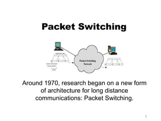
Around 1970, research began on a new form
of architecture for long distance
communications: Packet Switching.
1
2. Introduction
Packet Switching refers to protocols in
which messages are divided into packets
before they are sent. Each packet is then
transmitted individually and can even follow
different routes to its destination. Once all
the packets forming a message arrive at
the destination, they are recompiled into
the original message.
2
3. Packet Switching Operation
Data are transmitted in short packets. Typically
an upper bound on packet size is 1000 octets.
If a station has a longer message to send it
breaks it up into a series of small packets. Each
packet now contains part of the user's data and
some control information.
The control information should at least contain:
Destination Address
Source Address
Store and forward - Packets are received, stored
briefly (buffered) and past on to the next node
3
4. Advantages
Line efficiency
Single node to node link can be shared by many
packets over time
Packets queued and transmitted as fast as possible
Data rate conversion
Each station connects to the local node at its own
speed
Nodes buffer data if required to equalize rates
Packets are accepted even when network is busy
Delivery may slow down
Priorities can be used
4
5. Switching Technique - Virtual
Circuits and Datagrams
Station breaks long message into packets
Packets sent one at a time to the network
Packets handled in two ways
Datagram
Virtual circuit
5
6. Datagram Packet Switching
In datagram approach each packet is treated
independently with no reference to packets that
have gone before. No connection is set up.
Packets can take any practical route
Packets may arrive out of order
Packets may go missing
Up to receiver to re-order packets and recover
from missing packets
More processing time per packet per node
Robust in the face of link or node failures.
6
8. Virtual Circuit Packet
Switching
In the Virtual Circuit approach a pre-planned route is
established before any packets are sent.
There is a call set up before the exchange of data
(handshake).
All packets follow the same route and therefore arrive in
sequence.
Each packet contains a virtual circuit identifier instead of
destination address
More set up time
No routing decisions required for each packet - Less routing
or processing time
Susceptible to data loss in the face of link or node failure
Clear request to drop circuit
Not a dedicated path 8
10. Virtual Circuits vs. Datagram
Virtual circuits
Network can provide sequencing and error
control
Packets are forwarded more quickly
No routing decisions to make
Less reliable
Loss of a node looses all circuits through that node
Datagram
No call setup phase
Better if few packets
More flexible
Routing can be used to avoid congested parts of the
network 10
11. Packet switching -
datagrams or virtual circuits
Interface between station and network node
Connection oriented
Station requests logical connection (virtual circuit)
All packets identified as belonging to that connection
& sequentially numbered
Network delivers packets in sequence
External virtual circuit service
e.g. X.25
Different from internal virtual circuit operation
Connectionless
Packets handled independently
External datagram service
Different from internal datagram operation
11
18. Switching vs Routing
Switching Routing
path set up at connection can work as connectionless
time complex routing algorithm
simple table look up table maintainance via
table maintainance via protocol
signaling out of sequence delivery
no out of sequence delivery likely
lost path may lose robust: no connections lost
connection significant processing delay
much faster than pure output link decision based on
routing packet header contents - at
link decision made ahead of every node
time, and resources
allocated then 18