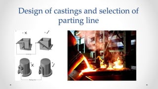
Design of castings and selection of the parting line
•Als PPTX, PDF herunterladen•
23 gefällt mir•16,238 views

General steps to be followed in the design of castings and the procedure to select the parting line in castings.

Empfohlen
Weitere ähnliche Inhalte
Was ist angesagt?
Was ist angesagt? (20)
Ähnlich wie Design of castings and selection of the parting line
Ähnlich wie Design of castings and selection of the parting line (20)
Mehr von Anand Prithviraj
Mehr von Anand Prithviraj (10)
Kürzlich hochgeladen
Kürzlich hochgeladen (20)
Design of castings and selection of the parting line
- 1. Design of castings and selection of parting line
- 2. Introduction • Successful casting practice requires the proper control of a large number of variables: characteristics of the metals (or alloys) casts, method of casting, mold/die materials, mold/die design, and various process parameters. • The flow of the molten metal in the mold cavities, the gating systems, the rate of cooling, and the gases evolved all influence the quality of a casting. • This presentation describes general design considerations and guidelines for metal casting and the selection of a parting line.
- 3. Design Considerations in Casting 1. Design the part so that the shape is cast easily. 2. Select a casting process and material suitable for the part, size, mechanical properties, etc. 3. Locate the parting line of the mold in the part. 4. Locate and design the gates to allow uniform feeding of the mold cavity with molten metal. 5. Select an appropriate runner geometry for the system. 6. Locate mold features such as sprue, screens and risers, as appropriate. 7. Make sure proper controls and good practices are in place.
- 4. Design Considerations in Casting - Design of cast parts • Corners, angles and section thickness: avoid using sharp corners and angles (act as stress raisers) and may cause cracking and tearing during solidification. Use fillets with radii ranging from 3 to 25 mm
- 5. Design Considerations in Casting - Design of cast parts Figure 1 Suggested design modifications to avoid defects in castings. Note that sharp corners are avoided to reduce stress concentrations.
- 6. Design Considerations in Casting - Design of cast parts • Sections changes in castings should be blended smoothly into each other. Location of the largest circle that can be inscribed in a particular region is critical so far as shrinkage cavities are concerned (a & b). Because the cooling rate in regions with large circles is lower, they are called hot spots. These regions can develop shrinkage cavities and porosity (c & d). • Cavities at hot spots can be eliminated by using small cores (e). It is important to maintain (as much as possible) uniform cross sections and wall thicknesses throughout the casting to avoid or minimize shrinkage cavities. Metal chills in the mold can eliminate or minimize hot spots.
- 7. Design Considerations in Casting - Design of cast parts Figure 12.2 Examples of designs showing the importance of maintaining uniform cross-sections in castings to avoid hot spots and shrinkage cavities.
- 8. Elimination of Hot Spots Figure 12.2 Examples of designs showing the importance of maintaining uniform cross-sections in castings to avoid hot spots and shrinkage cavities.
- 9. Design Considerations in Casting - Design of cast parts Figure 12.3 Examples of design modifications to avoid shrinkage cavities in castings. Figure 12.4 The use of metal padding (chills) to increase the rate of cooling in thick regions in a casting to avoid shrinkage cavities
- 10. Design Considerations in Casting - Design of cast parts o Flat areas: large flat areas (plain surfaces) should be avoided, since they may warp during cooling because of temperature gradients, or they develop poor surface finish because of uneven flow of metal during pouring. To resolve this one can break up flat surfaces with staggered ribs. o Shrinkage: pattern dimensions also should allow for shrinkage of the metal during solidification and cooling. o Allowances for shrinkage, known as patternmaker’s shrinkage allowances, usually range from about 10 to 20 mm/m. Table 12.1 gives the normal shrinkage allowance for metals that are commonly sand cast.
- 11. Design Considerations in Casting - Design of cast parts Figure: Adding ribs to flat region decreases warping and increases stiffness against bending moments
- 12. Shrinkage Allowance for Casting in Sand Molds
- 13. Design Considerations in Casting - Design of cast parts o Draft: a small draft (taper) typically is provided in sand mold pattern to enable removal of the pattern without damaging the mold. Drafts generally range from 5 to 15 mm/m. Depending on the quality of the pattern, draft angles usually range from 0.5o to 2o. o Dimensional tolerances: tolerances should be as wide as possible, within the limits of good part performance; otherwise, the cost of the casting increases. In commercial practices, tolerances are usually in the range of ± 0.8 mm for small castings. For large castings, tolerances may be as much as ± 6 mm.
- 14. Design Considerations in Casting - Design of cast parts o Lettering and markings: it is common practice to include some form of part identification (such lettering or corporate logos) in castings. These features can be sunk into the casting or protrude from the surface. o Machining and finishing operations: should be taken into account. For example, a hole to be drilled should be on a flat surface not a curved one. Better yet, should incorporate a small dimple as a starting point. Features to be used for clamping when machining.
- 15. Design Considerations in Casting - Locating and designing gates o The gates are connections between the runners and the part cavity. Some of the considerations in designing gating systems are: o Multiple gates often are preferable and are necessary for large parts. o Gates should feed into thick sections of castings. o A fillet should be used where a gate meets a casting; this feature produces less turbulence than abrupt junctions. o The gate closest to the sprue should be placed sufficiently far away so that the gate can be easily removed. This distance may be as small as a few mm for small casting and up to 500 mm for large parts.
- 16. Design Considerations in Casting - Locating and designing gates o The minimum gate length should be three to five times the gate diameter, depending on the metal being cast. The cross-section should be large enough to allow the filling of the mold cavity and should be smaller than the runner cross-section. o Curved gates should be avoided, but when necessary, a straight section in the gate should be located immediately adjacent to the casting.
- 17. Design Considerations in Casting - Runner design The runner is a horizontal distribution channel that accepts the molten metal from the sprue and delivers it to the gates. o One runner is used for simple parts, but-two runner systems can be specified for more complicated castings. o The runners are used to trap dross (dross is a mixture of oxide and metal and forms on the surface of the metal) and keep it from entering the gates and the mold cavity. o Commonly, dross traps are placed at the ends of the runners, and the runner projects above the gates to ensure that the metal in the gates is trapped below the surface.
- 18. Design Considerations in Casting - Designing other mold features o The main goal in designing a sprue is to achieve the required metal flow rates while preventing excessive dross formation. o Flow rates are determined such that turbulence is avoided, but the mold is filled quickly compared to the solidification time required. o A pouring basin can be used to ensure that the metal flow into the sprue is uninterrupted; also, if the molten metal is maintained in the pouring basin during pouring, then the dross will float and will not enter the mold cavity. o Filters are used to trap large contaminants and to slow metal velocity and make the flow more laminar. o Chills can be used to speed solidification of the metal in a particular region of a casting.
- 19. Design Considerations in Casting - Establishing good practices Some necessary quality control procedures: o Starting with a high-quality molten metal is essential for producing superior castings. Pouring temperature, metal chemistry, gas entrainment, and handling procedures all can affect the quality of the metal being poured into a mold. o The pouring of the metal should not be interrupted, since it can lead to dross entrainment and turbulence. o The different cooling rates within the body of a casting cause residual stresses. Stress relieving maybe necessary to avoid distortions of castings in critical applications.
- 20. Examples of Good and Poor Designs
- 21. Design Considerations in Casting - Locating the parting line o A part should be oriented in a mold so that the large portion of the casting is relatively lower and the height of the casting is minimized. o The parting line is a line or a plane separating the upper (cope) and lower (drag) halves of mold. In general, the parting line should be along a flat plane rather than be contoured. o Parting lines can be classified as flat, stepped, angled and profiled parting lines. o The parting line should be placed as low as possible relative to the casting for less dense metal (such as aluminum alloys) and located at around mid-height for denser metals (such as steels).
- 22. Design Considerations in Casting - Locating the parting line Figure 12.5 Redesign of a casting by making the parting line straight to avoid defects.
- 23. Factors affecting selection of parting direction and parting line • Undercut- A feature of part that is not mouldable in selected parting direction is called an undercut. • Having an undercut is not desirable as it increases process cycle time and, tooling and manufacturing cost. • For selecting an optimal parting direction or parting line the number of undercut are to be minimised
- 24. Factors affecting selection of parting direction and parting line • Draw- Draw is the minimum distance through which a component is linearly translated in order to clear it from the mould. • The draw distance is kept to a minimum for selecting a parting direction and a parting line. • Draw distance is compared with the smallest overall dimension to evaluate this criterion.
- 25. Factors affecting selection of parting direction and parting line • Projected area- It is the area of projection of a part on a plane perpendicular to parting direction. • The boundary of projected area gives the boundary of the parting surface. • Generally a parting direction with maximum projected area is selected as the optimal parting direction.
- 26. Factors affecting selection of parting direction and parting line • Draft- To facilitate removal of manufactured component from mould the cross-sectional area should gradually decrease from the parting surface in parting direction. • Necessary draft has to be applied to the part in the parting direction if the projected area does not decrease on the parting direction. • An optimal parting direction and line will have minimum possible draft.
- 27. Factors affecting selection of parting direction and parting line • Flash- Material flowing into gaps at the plane of separation of the two mould halves produces fin like protrusions or flash and is treated as imperfection. • This is generally trimmed after manufacturing. For optimal parting direction and parting line the flash must be less and easy to trim. • Flatness- The selection of the parting direction should ensure the flatness of the parting line. • A flat parting line alone can take care of the other aspects like side thrust, dimensional stability, sealing off, flash etc. • The complexity of a non-flat parting line should be minimum possible
- 28. Factors affecting selection of parting direction and parting line • Dimensional stability- It refers to reduction of the mismatch between the mould segments which affects the faces through which the parting line passes. • In order to obtain dimensional stability the faces requiring high dimensional stability and tolerances are kept completely on either side of the parting line • Side thrust- Side thrust occurs in die casting when the parting line is non-planer and asymmetric about vertical plane. • Side thrust can be reduced with the selection of a flat parting line. • In the process of selection of the parting direction and line, side thrust is taken into account as side thrust is responsible for occurrence of mismatch between two mould parts.
- 29. Factors affecting selection of parting direction and parting line • Placement and design of overflow wells and vents- Generally overflow wells and vents are placed opposite to the feeding system. • Overflow wells appear as extra material on the casting after solidification which must be removed. This causes some marks on the casting. • Parting line should be such that the overflow wells should not be placed on surfaces requiring high surface finish. • Placement of ejector pins- Placement of the ejector pins is done by considering the strength of the part which is function of wall thickness. • The ejector pins should be placed on surface with considerable strength and that does not require high surface finish.
- 30. Factors affecting selection of parting direction and parting line • Trimming and finishing operations- Trimming and finishing operations are used to cut the unnecessary flash and feeding system from the casting. • Sometimes even a flat parting line with inaccessible corners could pose problems for trimming and finishing operations. • The parting line should be such that the trimming and finishing operations could be performed easily without considerable investment in the trimming dies. • Placement of inserts- Some casting require placement of inserts. The selection of parting line also depends on easy and suitable placement of the insert. • Parting line should be selected such that the inserts maintain their position even under the feeding pressure.
- 31. Factors affecting selection of parting direction and parting line • Amount of scrap generated- The metal is injected into the cavity through feeding system which comprises of sprue, biscuit, runners and gates. • The feeding system remains attached to the cast part after solidification along with the flash at the parting line. • This extra material is then trimmed off and scrap is generated. • Parting line should be so located that the scrap produced is less.
- 32. Decision criteria for parting line selection • Factors affecting parting line selection are rated according to high, medium and low priority. • The criteria with high priority are number of undercuts, draft, projected area and dimensional stability. • Criteria with medium priority are draw, flash, flatness and placement of ejector pins. • The criteria with low priority are side thrust, placement of overflow wells, trimming and finishing operations, scrap generated. • Each parting line is evaluated using these criteria on a five point scale viz. excellent (E), good (G), fair (F), poor (P) and unacceptable (U).
- 33. Implementation
- 34. Conclusion • A method for optimal selection of parting direction and parting line has been presented. • Factors affecting selection of parting direction and parting line have been discussed and proposed. • Candidate parting directions are identified by analysing different features of the part. • Possible parting lines for suitable parting direction are identified and the Dominic method of concept evaluation can be used to identify the optimal parting line. Reference: 1. “Optimal selection of parting line for die-casting” Ranjit Singh and Jatinder Madan, 2 nd National conference on Precision Manufacturing (26-27 March, 2010), SLIET Longowal.