Transformer Interfacing with Laptop
•
0 gefällt mir•98 views

Interfacing of Transformer with Laptop and frequency control by Aurduino

Empfohlen
Weitere ähnliche Inhalte
Was ist angesagt?
Was ist angesagt? (20)
Ähnlich wie Transformer Interfacing with Laptop
Ähnlich wie Transformer Interfacing with Laptop (20)
Mehr von COMSATS Abbottabad
Mehr von COMSATS Abbottabad (20)
Kürzlich hochgeladen
Kürzlich hochgeladen (20)
Transformer Interfacing with Laptop
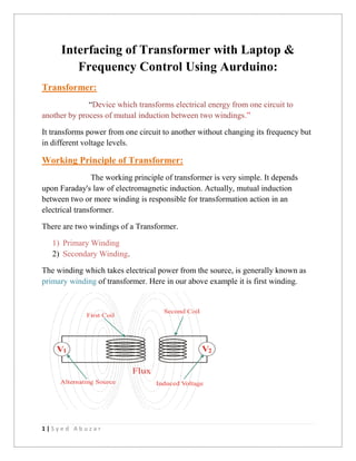
- 1. 1 | S y e d A b u z a r Interfacing of Transformer with Laptop & Frequency Control Using Aurduino: Transformer: “Device which transforms electrical energy from one circuit to another by process of mutual induction between two windings.” It transforms power from one circuit to another without changing its frequency but in different voltage levels. Working Principle of Transformer: The working principle of transformer is very simple. It depends upon Faraday's law of electromagnetic induction. Actually, mutual induction between two or more winding is responsible for transformation action in an electrical transformer. There are two windings of a Transformer. 1) Primary Winding 2) Secondary Winding. The winding which takes electrical power from the source, is generally known as primary winding of transformer. Here in our above example it is first winding.
- 2. 2 | S y e d A b u z a r The winding which gives the desired output voltage due to mutual induction in the transformer, is commonly known as secondary winding of transformer. The rate of change of flux linkage depends upon the amount of linked flux with the second winding. So, it is desired to be linked to almost all flux of primary winding to the secondary winding. This is effectively and efficiently done by placing one low reluctance path common to both of the winding.
- 3. 3 | S y e d A b u z a r Aurduino: Arduino is an open-source electronics platform based on easy-to-use hardware and software. Arduino boards are able to read inputs - light on a sensor, a finger on a button, or a Twitter message - and turn it into an output - activating a motor, turning on an LED, publishing something online. You can tell your board what to do by sending a set of instructions to the microcontroller on the board. To do so you use the Arduino programming language (based on Wiring), and the Arduino Software (IDE), based on Processing.
- 4. 4 | S y e d A b u z a r PWM: Pulse Width Modulation, or PWM, is a technique for getting analog results with digital means. Digital control is used to create a square wave, a signal switched between on and off. This on-off pattern can simulate voltages in between full on (5 Volts) and off (0 Volts) by changing the portion of the time the signal spends on versus the time that the signal spends off. The duration of "on time" is called the pulse width. To get varying analog values, you change, or modulate, that pulse width. If you repeat this on-off pattern fast enough with an LED for example, the result is as if the signal is a steady voltage between 0 and 5v controlling the brightness of the LED.
- 5. 5 | S y e d A b u z a r Working Of Project: As all major parts are discussed above. The main component used in the project is Aurduino which provides pulses (PWM). As we know that Transformer works on alternating input given to it. So for producing alternating input I used Aurduino Uno for triggering the pulses on gate of Mosfet (z44n). The MOSFET (Metal Oxide Semiconductor Field Effect Transistor) transistor is a semiconductor device which is widely used for switching. When there is no voltage on the gate the device does not conduct. More is the voltage on the gate, the better the device can conduct. When MOSFET receives the triggered pulses from aurduino, it gives output when it receives the +5V and remains off for 0V. Now this input is given to the Transformer and it works as alternating input which is amplified by the transformer at output. If I increase the frequency of PWM , output of the Transformer is also increased because rate of change of flux increases and similarly for decreasing the frequency, output will be reduced. The rated frequency for transformer is 50Hz. I used 12-0-12 to 220V Transformer.
- 6. 6 | S y e d A b u z a r Circuit Diagram :