

Empfohlen
Weitere ähnliche Inhalte
Was ist angesagt?
Was ist angesagt? (20)
Andere mochten auch
Ähnlich wie Experiment no. 9
Ähnlich wie Experiment no. 9 (20)
Kürzlich hochgeladen
Kürzlich hochgeladen (20)
Experiment no. 9
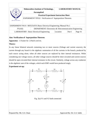
- 1. Maharashtra Institute of Technology, Aurangabad LABORATORY MANUAL Practical Experiment Instruction Sheet EXPERIMENT TITLE : Verification of Superposition Theorem. EXPERIMENT NO.9 : MIT(T)/ETC/Basic Electrical Engineering /Manual No.1 FY(All) DEPARTMENT: Electronics & Telecommunication Engineering LABORATORY : Basic Electrical Engineering Location Part I Page 41 Aim: Verification of Superposition Theorem. Apparatus: 1.Trainer kit 2.Patch cord etc. Theory: In any linear bilateral network containing two or more sources (Voltage and current sources), the current through any branch is the algebraic summation of all the currents in the branch, produced by each source acting alone, when all other sources are replaced by their internal resistances. While considering one voltage source, all other voltage sources should be short circuited and current sources should be open circuited their internal resistance in the circuit. Similarly, voltage across any conductor is the algebraic sum of the voltages, which each EMF would have produced singly. Experiment set-up: Fig. 2(a) V1 and V2 both connected Prepared By: Mr. S.S. Chate Approved By: Dr. G.S. Sable
- 2. Maharashtra Institute of Technology, Aurangabad LABORATORY MANUAL Practical Experiment Instruction Sheet EXPERIMENT TITLE :Verification of Superposition Theorem. EXPERIMENT NO.9 : MIT(T)/ETC/Basic Electrical Engineering /Manual No.1 FY(All) DEPARTMENT: Electronics & Telecommunication Engineering LABORATORY : Basic Electrical Engineering Location Part I Page 42 Fig. 2(b) When V1 acting alone Fig.-2(c) When V2 acting alone Prepared By: Mr. S.S. Chate Approved By: Dr. G.S. Sable
- 3. Maharashtra Institute of Technology, Aurangabad LABORATORY MANUAL Practical Experiment Instruction Sheet EXPERIMENT TITLE :Verification of Superposition Theorem. EXPERIMENT NO.9 : MIT(T)/ETC/Basic Electrical Engineering /Manual No.1 FY(All) DEPARTMENT: Electronics & Telecommunication Engineering LABORATORY : Basic Electrical Engineering Location Part I Page 43 Component values: R1 = R2 = 390Ω, R3 = 680Ω, R4 = R5 = 100Ω. Procedure: 1. Connect the main cord to 230v, 50Hz AC supply and switch on trainer kit. 2. Connect V1 to the voltmeter and adjust voltage to read e.g. 5V DC and similarly adjust V2 e.g. 5V DC. 3. Do the connection as shown in fig. 2(a) by using patch cords. 4. Note the value of V1, V2 and current (I) through R3. 5. Do the connection as shown in fig. 2(b) only V1 connected (with same voltage as in steps (2) and note the readings (I’). 6. Repeat the steps (5) when only V2 connected as shown in fig.2( c ) and same value of V2 as in steps (2) Note the ammeter reading through R3 (I”). 7. Now verify the superposition theorem. I = I’ + I” 8. Repeat the experiment for different values of V1 and V2. Record reading in observation table 1. Refer connection diagram fig.2 (a), (b) (c). Current meter between H and I. Prepared By: Mr. S.S. Chate Approved By: Dr. G.S. Sable
- 4. Maharashtra Institute of Technology, Aurangabad LABORATORY MANUAL Practical Experiment Instruction Sheet EXPERIMENT TITLE :Verification of Superposition Theorem. EXPERIMENT NO.9 : MIT(T)/ETC/Basic Electrical Engineering /Manual No.1 FY(All) DEPARTMENT: Electronics & Telecommunication Engineering LABORATORY : Basic Electrical Engineering Location Part I Page 44 Connection diagram for second set: Fig-3(a) Both V1 and V2 acting alone Fig-3(b) When V2 acting alone Prepared By: Mr. S.S. Chate Approved By: Dr. G.S. Sable
- 5. Maharashtra Institute of Technology, Aurangabad LABORATORY MANUAL Practical Experiment Instruction Sheet EXPERIMENT TITLE :Verification of Superposition Theorem. EXPERIMENT NO.9 : MIT(T)/ETC/Basic Electrical Engineering /Manual No.1 FY(All) DEPARTMENT: Electronics & Telecommunication Engineering LABORATORY : Basic Electrical Engineering Location Part I Page 45 Fig-3(c ) When V1 acting alone Procedure: 1. Do the connection as in fig-3(a) adjust the voltages V1, V2 and note down the readings V1, V2 and I1. 2. Note the readings when V1 acting alone I’1 3. Note the value of I”1 when V2 acting. 4. Verify the superposition theorem. I1 = I’1 + I”1 5. Repeat the experiment for different values of V1 and V2. Record your readings in observation table-2. Refer connection diagram fig-3(a), (b) and ( c ). Prepared By: Mr. S.S. Chate Approved By: Dr. G.S. Sable
- 6. Maharashtra Institute of Technology, Aurangabad LABORATORY MANUAL Practical Experiment Instruction Sheet EXPERIMENT TITLE :Verification of Superposition Theorem. EXPERIMENT NO.9 : MIT(T)/ETC/Basic Electrical Engineering /Manual No.1 FY(All) DEPARTMENT: Electronics & Telecommunication Engineering LABORATORY : Basic Electrical Engineering Location Part I Page 46 Observation Table: Sr. No. Observations Calculations V1 Volts V2 Volts I (mA) V1 & V2 Connected I’ (mA) With V1 acting alone I” (mA) With V2 acting alone I = I’ + I” (mA) 1 2 3 4 Conclusion: As I = I’ + I”, which verify the superposition theorem. The small difference is due to meter error, observation error and due to neglecting the internal resistance. Prepared By: Mr. S.S. Chate Approved By: Dr. G.S. Sable