Design and Optimization of steering and Suspension System of All Terrain Vehicle
Poster A3 Sarunas Dirse
1. 3D printed Front Suspension Upright for
KU e-racing Formula Student car
Student: Sarunas Dirse BSc Motorsport Engineering
Supervisor: Prof. M. Necip Sahinkaya
FACULTY OF SCIENCE, ENGINEERING AND COMPUTING, SCHOOL OF MECHANICAL AND AUTOMOTIVE ENGINEERING
Definition: Front upright is a
complex component of front
suspension which is also commonly
known as a wheel knuckle. It
combines suspension geometry
elements such as caster and
steering axis inclination. Suspension
upright also transfers loads from
wheel hub to upper and lower
control arms.
Problem: lack of custom made
uprights in the market. This upright
design is dictated by the specific
suspension geometry in KU e-racing
car.
INTRODUCTION
OBJECTIVES
1. To design front suspension
geometry (caster, camber, toe
and steering axis inclination).
2. To create an upright which
complies with geometry and can
withstand given forces.
3. To conduct FEA analysis in
order to improve the design.
4. To manufacture the component
and assemble the suspension.
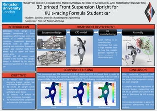
COMPONENT DEVELOPMENT
COMPONENT TESTING
This component was FEA tested with 1.7 G’s braking and 0.9 G’s lateral force in order to
simulate hard braking and cornering conditions. Maximum estimated weight of the car with a
driver is 400kg. Material used is Aluminum 7075 T-6 . The following results were achieved:
Stress Strain Displacement
After conducting research and
carrying out numerous experiments
the unique front suspension upright
has been designed.
It complies with the regulations of
Formula Student competition and
will be 3D printed and used in the
race at Silverstone by KU e-racing
team.
Tremendous knowledge is gained in
suspension components and FEA
analysis.
CONCLUSION
Suspension design
3D
manufacturing
AssemblyCAD model
Laser melting is an
manufacturing
technology that uses
a high powered laser
to fuse fine metallic
powders together to
form functional 3-
dimensional part.