
Empfohlen
Weitere ähnliche Inhalte
Was ist angesagt?
Was ist angesagt? (20)
Ähnlich wie A review of the application of Acoustic Emission Technique in Engineering
Ähnlich wie A review of the application of Acoustic Emission Technique in Engineering (20)
Kürzlich hochgeladen
Kürzlich hochgeladen (20)
A review of the application of Acoustic Emission Technique in Engineering
- 1. Structural Engineering and Mechanics, Vol. 54, No. 6 (2015) 1075-1095 DOI: http://dx.doi.org/10.12989/sem.2015.54.6.1075 1075 Copyright © 2015 Techno-Press, Ltd. http://www.techno-press.org/?journal=sem&subpage=8 ISSN: 1225-4568 (Print), 1598-6217 (Online) A review of the application of acoustic emission technique in engineering S. Gholizadeh , Z. Lemana and B.T.H.T. Baharudinb Department of Mechanical and Manufacturing Engineering, Universiti Putra Malaysia, 43400 Serdang, Selangor, Malaysia (Received September 30, 2014, Revised February 19, 2015, Accepted February 23, 2015) Abstract. The use of acoustic emission (AE) technique for detecting and monitoring damages and the progress on damages in different structures is widely used and has earned a reputation as one of the most reliable and well-established technique in non-destructive testing (NDT). Acoustic Emission is a very efficient and effective technology used for fracture behavior and fatigue detection in metals, fiberglass, wood, composites, ceramics, concrete and plastics. It can also be used for detecting faults and pressure leaks in vessels, tanks, pipes, as well as for monitoring the progression of corrosion in welding. This paper reviews major research developments over the past few years in application of acoustic emission in numerous engineering fields, including manufacturing, civil, aerospace and material engineering. Keywords: application ofAE; acoustic emission; non-destructive testing; NDT applications 1. Introduction Acoustic emission is one of the new introductions to the Non-Destructive Evaluation (NDE) industry. It was introduced to address the limitations of previous NDE technologies on applications or to cut down financial costs of evaluation. The need to evaluate AE‟s suitability for use in engineering applications was instigated by some new groups of researchers from Japan, Europe and the USA in the late 1970s and early 1980s (Barber 2006). The definition of AE as given by ASTM E1316 (2014) is “The class of phenomena whereby transient elastic waves are generated by the rapid release of energy from a localized source or sources within a material, or the transient wave(s) so generated”. Acoustic emission or stress wave emission as it is often called describes the acoustic stress waves that emerged as a result of a rapid release of energy because of the microstructural changes that occur in materials (Musa 2002). AE is a very efficient and effective technology used for fracture behavior and fatigue detection in metals, fiberglass, wood, composites, ceramics, concrete and plastics (Huang et al. 1998). It can also be used for detecting faults and pressure leaks in vessels, tanks, pipes, as well as for Corresponding author, Msc. Student, E-mail: vsco_gh@yahoo.com a Ph.D., E-mail: zleman@upm.edu.my b Ph.D., E-mail: hangtuah@upm.edu.my
- 2. S. Gholizadeh, Z. Leman and B.T.H.T. Baharudin monitoring the progression of corrosion and welding (Boehnlein et al. 2004). In order to address the challenges posed by audible sounds, which were reported by researchers particularly in the 1990s to occur during AE material deformation investigations, led to the advent of the technological era (Jackson et al. 1998). This brought about several advances particularly in the areas of rapid measurement instrumentation in AE. For example, advanced digital instruments can now be used to digitize and store large numbers of high speed digital waveform signals of AE (Holford et al. 2009). 2. Inspection requirements Common instruments used in AE include preamplifiers, amplifiers, filters, sensors and other data collection, analysis and storage equipment like computers, oscilloscopes and voltmeters (NDT 2012, Pollock 1989). Preamplifiers are used for the prevention of loss of signal and to reduce the interference from noise while the piezoelectric sensors are used for the conversion of mechanical AE waves into electrical voltages (PAC 2005). The overall objective of the measurement is to determine the various AE parameters such as the frequency range (controlled by filters) that exist in the system by observing and measuring the performance of AE amplifiers and sensors. These are very useful mechanisms for environmental noise discrimination and for identifying deterioration through the measurement of parameters such as event, count, energy-moment, maximum amplitude, hit, energy, arrival-time difference, RMS (root mean square) voltage, rise time, spectrum, frequency and duration (Grosse et al. 2008). 3. Overview on acoustic emission waveform parameters In the 1950s and „60s researchers investigated the essentials of AE, established instrumentation particularly for AE, and considered the AE behavior of numerous resources. AE was starting to be recognized for its exclusive competences as a NDT technique intended for checking dynamic procedures. In the 1970s, studies were carried out to develop more synchronized and directed through the construction of the working groups, and its usage as an NDT process continued to increase for industrial applications. During the 1980s, the computer developed as a basic component for both instrumentation, data examination, and nowadays it has flashed a resurgence of chances intended for study and improvement. Nowadays, waveform-based AE investigation is typical and there is a change in AE accomplishments through more importance on uses than on study (Drouillard 1996). Two types of analysis can be considered by AE. One is under time domain waveform which is related to basic parameter in a time domain of testing and the second is frequency domain waveform which considers the signal parameters with upcoming recorded frequency under testing. The extensively used signal measurement parameters in AE signal examination are counts, duration, amplitude, rise time, and the measured area under the corrected signal envelope that is also called relative energy as shown in Fig. 1. Amplitude: It is represented with A and shows the highest peak of the voltage signal. This is identical significant characteristic since it openly controls how much the AE event is detectable. Amplitude of the AE signal is immediately related to the magnitude of the source and varies over a wide range from micro volts to volts. According to Unnþórsson (2013), the amplitudes of AE are 1076
- 3. A review of the application of acoustic emission technique in engineering Fig. 1 Acoustic emission events recorded by using definition (Unnþoórsson 2013) usually mentioned in decibel scales. For example 1 µV at the transducer is defined as 0 dB, 10 µV as 20 dB, and 100 µV as 40 dB. Counts: Counts commonly are presented by N. When the amplitude of the signal is larger than the threshold, the number of pulses emitted by measurement circuitry is defined as N. Counts strongly rely on the AE properties and reverberant nature of the sensor and specimen material. Hits: When a signal exceeds the threshold consequently a system channel accumulates data, this signal is known as the hit and describes an AE event. The number of events or hits per time determines the event rate. Both number of hits and number of counts determines the quantity of an AE activity. Duration, D: The time interval between a signal trigger and the time it reduces below the threshold value is known as the duration of the signal. MARSE Energy: Measured Area of the Rectified Signal Envelope is known as MARSE and sometimes represented by E and referred to as energy counts. This area is the zone below the envelope of the signal which is rectified and measured from the sensor. Energy is preferred over counts since it is sensitive to amplitude as well as duration, and it relies fewer on the threshold location and functioning frequency. Absolute (true) energy also is resulting from squared voltage signal divided by reference resistance of 10 kΩ over the time duration of acoustic emission waveform packet. According to (PAC 2005), this parameter indicates the true energy of an AE event from transient signals or of certain data rate interval of continuous AE signals. The absolute energy of a detected AE burst signal commonly expressed in atto-joules (1 aJ=10-18 J) and values can be mentioned in logarithmic scales (dB, decibels) (ASTM E1316). The energy is defined as Et= 1 2 ∫ ∮ (t)dt 2 + t2 t1 - 1 2 ∫ ∮ (t)dt 2 − t2 t1 (1) Rise time: Rise time is presented by R and defines the time interval between the maximum amplitude of the burst signal and the first threshold crossing. This parameter is frequently used when time dependent processes such as vibration or dynamic loading are involved. 1077
- 4. S. Gholizadeh, Z. Leman and B.T.H.T. Baharudin Threshold: Threshold is a kind of set up parameter which is used for the elimination of electronic background noises. Its main objective is to eliminate as much background noise as it can. However, a balance should be struck so that the threshold does not also eliminate signals that are weak but useful given that background noises are characterized by low amplitude. To run proper AE monitoring, certain parameters of the data acquisition systems need to be set according to the testing material and the existing noise level. These parameters which are categorized as control parameters can be mentioned as Peak Definition Time (PDT), Hit Definition Time (HDT) and Hit Lock out Time (HLT) that are timing parameters of the signal acquisition process and contain material specific values. PDT identifies the signal peak for rise time and peak amplitude measurements. HDT quantifies a signal to be accounted as one hit and appropriate HLT setting ensures the ability to discard the spurious signal decay measurements. 3. Application of AE in engineering Several industries such as power generation, refineries, structures (cranes, bridges, etc.), pipelines, aircraft, etc., make use of AE for nondestructive testing in their operations. Since its advent in Germany in the 1950s, AE has been very widely applied especially in the areas of quality control in manufacturing operations and process monitoring. AE systems are also very useful applications of composite structures like advanced aerospace materials, reinforced plastics and fiberglass and can also be employed in research applications and quality control in manufacturing operations (Li 2002). 3.1 Manufacturing Dornfeld (1992) noted that although AE was initially intended for non-destructive testing of structures, today it has been widely applied as a technique for monitoring manufacturing processes because of its sensitivity to process parameters. Several researchers have looked into the various challenges faced in monitoring manufacturing processes such as Dornfeld et al. (2003), Haber et al. (2004), Jemielniak and Arrazola (2008), but focused mainly on sensor techniques and how they fit into future manufacturing requirements. Likewise, Chen and Li (2007) investigated the AE signals of wavelet analysis for tool condition monitoring, while, Sun and Tang (2002) used wavelet transform modulus maxima to monitor operating bearings in order to identify any abrupt changes that may occur in the signals of the vibration. Teti et al. (2010) conducted a very detailed review on sensor technology and the techniques employed for processing data in automated machine by using several sensors of varying levels of applicability based on the phenomenon type, precision level or control parameter requiring measurement so as to capture the necessary information on the manufacturing process (Lee et al. 2006). Fig. 2 shows an update of a related diagram from the aforementioned review paper (Dornfeld et al. 2003), and the diagrams of other sensors based on their class and applicability at both control parameter type and level of precision (beginning from the conventional scale edging downwards to the level of ultra-precision material removal at the ordinate scale) (Dornfeld et al. 2003, Lee et al. 2006). The use of AE as a monitoring technique for machining operations comes with a lot of advantages, one of which is its ability to discriminate between environmental noise and machine vibrations from those of AE signals due to high frequency range and sensitivity of AE signals, thus preventing it from interfering with the cutting operation (Govekar et al. 2000). This characteristic 1078
- 5. A review of the application of acoustic emission technique in engineering Fig. 2 Sensor application vs. level of precision and control (Dornfeld et al. 2003) has made AE signal one of the most preferred tools used for process monitoring. The resulting AE signal continuously generated due to friction between the tool and work piece provides rich information regarding the cutting process. Different techniques and methodologies exist for monitoring of wears in tools used in welding (Suresha and Rajaprakash 2009, Zeng et al. 2006), turning (Jemielniak et al. 2011, Sharma et al. 2008), forming (Hao et al. 2000), milling (Mathew et al. 2008, Marinescu et al. 2008), grinding (Jayakumar et al. 2005), drilling (Arul et al. 2007, Velayudham et al. 2005). 3.2 Civil Another method used for the procedure of implementing a damage characterization strategy for maintenance purposes in engineering structures is structural health monitoring (SHM) (Brown et al. 2010). SHM employs AE technique in detecting early cracks in structures. It relies on the high frequency ultrasonic waves generated energy that is rapidly emitted from a material, right from the initial to growth progression of cracks. This AE technique makes it possible to monitor structures in real-time, thereby making it enabling the immediate detection of signals caused by cracks as soon it occurs (Kaphle 2012). The two basic types of AE monitoring strategies which can be applied are local and global monitoring strategies. Global monitoring strategy aids in the assessment of the whole integrity of the structure, whereas the local monitoring strategy is concerned with a particular damage area (Carlos et al. 2000). The wide applicability of AE technique is evident in several metal piping system evaluations and fibreglass reinforced plastics (FRP) (Ai et al. 2010, Oliveira et al. 2008), concrete bridges (Golaski et al. 2002), premature crack detection, fatigue crack development monitoring and the correlation of crack development with AE activity in steel parts (Keshtgar et al. 2013, Yu et al. 2011, Yu et al. 2011). A detailed discussion on AE fracture in metals is presented by (Ono 2011), while cracking in concrete is well discussed by (Kishi et al. 2000). Most common long-term assessment conditions due to damages experienced on concrete bridges are reinforcement corrosion and its associated cracks. Several research centers such as 1079
- 6. S. Gholizadeh, Z. Leman and B.T.H.T. Baharudin Fig. 3 Composites ratio in structural aircraft weight during last decade in commercial and military aircraft (Ono and Gallego 2012) highway agencies and universities are seeking ways through which AE can be implemented on concrete bridges (Watson et al. 2005). Vogel et al. (2006) discussed the processes involved in pre- stressed concrete bridges. They found that the use of AE for new crack monitoring was very significant as most concrete structures do not exhibit any sign of cracks at their initial stage of their service life. Recent findings on AE activities include Reiterer et al. (2000), who used a wedge-splitting configuration to determine a crack's uniform growth in both soft and hard woods by investigating the emission features resulting from mode I fracture in the plane normal to the radial direction. Aicher et al. (2001) looked at the damage caused in softwood generated by tension from loading specimens in a plane normal to the tangential direction. 3.3 Aerospace The application of AE took center stage after it was employed in developing reinforced glass- fiber composite rocket motorcases that were used in 1962 for Polaris A3 circa. It was also used to test Apollo lunar module propellant tanks and various aerospace applications. AE variations were first noted by Aerojet engineers, who identified different emissions from fiber failures, interlaminar failures and resin failures (Green et al. 1964, Green 2006), thus leading to the modification of the manufacturing processes for example, shear stress could be reduced by modifying the design such that the geometrical inflection points are eliminated (Asakawa et al. 1965). The use and significance of composite structural components is on the increase particularly in commercial aircrafts such as (B787, Airbus A380, F35, Typhoon) due to the superior strength features they have over metallic properties. The applications of AE real-time monitoring in mechanical tests are evident in the traditional polymer composites, which are reinforced with fibers (Park et al. 2004), glass (Benevolenski and Karger‐Kocsis 2001, Margueres et al. 2000), or 1080
- 7. A review of the application of acoustic emission technique in engineering carbon (Mizutani et al. 2000). These studies employed classical NDT application analyzed at various stages with sound progressive analysis with the goal of accepting or rejecting the stress material to the measurement and localization of accumulated damage. Pawar and Ganguli (2007) did a comprehensive review of various techniques used in helicopter rotors. Pullin et al. (2010) determined the distinct correlation between AE and crack growth and also used TRL5 (technology readiness level of five) to detect landing gears fractures in AE. Takeda (2008) did a study on monitoring damages with small-diameter optical fiber sensors and structural health monitoring of composite structures. AE was monitored with Full Scale Aircraft Structure Test Evaluation and Research (FASTER) in several honeycomb sandwich composites curved fuselage panes, with different scenario of damage, placed in Atlantic City (US). Fiber-Bragg grating (FBG) sensors and combined with piezoelectric actuators for Lamb wave inspection of carbon fiber reinforced plastic (CFRP) structures by Leone et al. (2008). Several recent studies on NDT in aircraft manufacturing can also be found in Giurgiutiu et al. (2003), Roach (2008), Schnars and Henrich (2006), Speckmann and Henrich (2004), Ullmann et al. (2010). There are several difficulties faced in using composite components by NDE/NDT during the manufacturing process, flight conditions, SHM, and service inspections. Several tests have been carried out in laboratories on large composite components especially in the last decades for aircraft structures (Ono and Gallego 2012). The increased and varying application of composites in various military and commercial aircrafts is shown in Fig. 3. 3.4 Material engineering 3.4.1 Composite AE originates from stress waves generated as a result of the growth or movement that takes place in solid defects. AE, unlike other techniques which can only detect geometrical discontinuities, detects fiber breakage movement, delamination (debonding of neighbouring plies) in laminated composite plates, matrix cracking and fiber pull-out (Diamanti and Soutis 2010). Majority of AE is caused by the rubbing or friction that takes place between damaged components in the composite. Some studies have looked into the potential application of AE technique in assessing the impact of the damage (Aymerich and Staszewski 2010), and understanding the behavior of the fracture of composite materials (Pappas and Kostopoulos 2001). AE was used by Szabó et al. (2004) to monitor the single-edge notched tensile (SENT) samples (notch length 10 mm) in polypropylene/polyamide (PP/PA) blends (with different concentration of PA: 0, 10, 20, 30, 40 and 50 wt%) reinforced by short basalt fiber (De Groot et al. 1995) at various contents (0, 10 and 20 wt%). Shen et al. (2002) proposed a model to explain the relationship between AE signals and force that generates deformation in plastics. Other researches have looked into the application of AE technique for damage evolution analysis and failure detection methods in traditional polymer composites reinforced with glass (Oskouei and Ahmadi 2010), aramid fibres (Caneva et al. 2008, Claudio Caneva et al. 2007), or carbon (Chen and Liu 2008, Liu et al. 2012). Nevertheless, there are not many studies on damage mechanisms in composites reinforced with natural fibers in AE such as kenaf, hemp, flax and jute (Anuar et al. 2007, Czigány et al. 2005, Dogossy and Czigány 2006, Kocsis and Czigany 2007, Szabó et al. 2004). The use of AE method to investigate the behavior of fracture and failure in biodegradable jute fabric reinforced thermoplastic polyester composites was carried out by Acha et al. (2006). While the correlation that exists between AE amplitude, elongation and cumulative hits, and elongation on wood flour filled polypropylene composites was shown by Dányádi et al. 1081
- 8. S. Gholizadeh, Z. Leman and B.T.H.T. Baharudin Fig. 4 AE signals of [±_62]12 cross-ply composite: matrix cracking (A signal), fiber- matrix debonding (B signal) and delamination (D signal) (Marec et al. 2008) Fig. 5 AE signals of SMC composite: matrix cracking (A signal), fiber-matrix debonding (B signal) and fiber failure (C signal) (Marec et al. 2008) (2006). Romhány et al. (2003) used AE to monitor and identify the sequence of failure mode that occurred in flax fiber reinforced composites during a tensile test. Their study revealed the possibility of identifying, during the failure of a composite, the AE amplitudes released by the flax fibers, despite the fact the previous values are lowered due to the damping effects of the matrix. Marec et al. (2008) investigated the local damage of composite materials based on the acoustic emission signal analysis. The results clearly identified the damage mechanisms in various composite materials: cross-ply composites and sheet molding compound (SMC) under tensile tests. This study also indicated the time evolution of damage mechanisms in these materials till the global failure and identified the most critical damage mechanisms. Matrix cracking and fiber- 1082
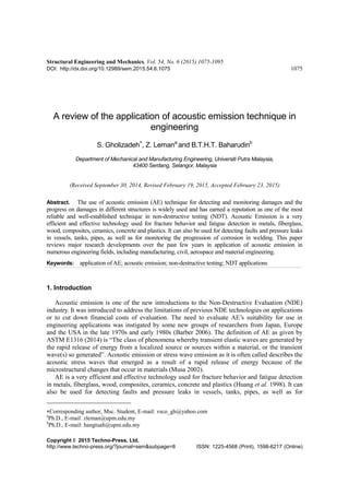
- 9. A review of the application of acoustic emission technique in engineering matrix debonding occur with delamination for the cross-ply composite material. In the SMC composite, matrix cracking, fiber matrix debonding, and fiber failure were observed. The identified A, B and D signals for the cross-ply composite and A, B and C for the SMC composite are presented in Figs. 4 and 5. 3.4.2 Metal The signals generated from AE are subject to both dispersion and attenuation due to the elasticity of the waves. Majority of the studies carried out in this domain with regards to monitoring AE in metals are mostly focused on specimens with thin plate geometries (Aggelis and Matikas 2012, Sedlak et al. 2009). However, by definition, propagation in thin plates is dispersive (Brepta et al. 1996, Rose 2004), because of the varying phase velocities at which different frequencies are propagated. According to Brown et al. (2010) there are four-point bending in which AE amplitudes correlate to stress in composite metal specimens. Dang Hoang et al. (2010) showed the relationship that exists between the duration of AE energy and the failures in a central bolt-connected aluminum plates. In a similar study, the relationship between the count rates in AE events and crack propagation rates in steel and welded steel compact tension (CT) specimens under fatigue was studied by Roberts and Talebzadeh (2003). Aggelis et al. (2011) found that some parameters like rise angle (RA), duration and rise time are very sensitive to the rate of crack propagation and are useful in the characterization of the transition to shear failure from in CT specimens under fatigue. Also Boschetto and Quadrini (2011) found that when metal powder is dropped in a controlled manner on a metal plate, the number of waveform counts was seen to be indicative to particle diameter. Furthermore, the study conducted by Han et al. (2011) on fatigue properties in a micro-alloyed steel and welds and AE characterization of fractographic and micro- structural observations reveal that AE can be used as a monitoring mechanism for damage caused by fatigue in structures due to its sensitivity to changes that occur within the fracture mode. Fig. 6 shows the relationships between the AE counts rates (dC/dN) and stress intensity factor ranges (ΔK) for different specimens. The AE counts rates increased in a linear relationship with the increase in ΔK on the log-log axes. Moreover, higher AE counts rates were also observed in the welded specimens than in the base metal specimens. In addition, the slopes of the lines for the Fig. 6 Relationships between crack growth rates and AE counts rates with ΔK for the base metal and weld under the peak loads of 16 kN and 20 kN (Han et al. 2011) 1083
- 10. S. Gholizadeh, Z. Leman and B.T.H.T. Baharudin Fig. 7 Comparison of the LEFM and AE transitions (Han et al. 2011) welded specimens were higher than the base metal specimens, also suggesting that the weld generated more AE signals during fatigue crack propagation. It was known that the stable and unstable crack propagations are generally identified by different slopes in the log-log plot of da/dN versus ΔK in the classical linear elastic fracture mechanics (LEFM). Fig. 7 shows for a base metal specimen, when the AE transition occurres at ΔK=56 MPa m1/2 , there is no change in the linear relationship between da/dN and ΔK on the double logarithmic axes. Until ΔK=70 MPa m1/2 , an unapparent change in the slope is observed. Thus, the AE stage transition precedes the unstable crack propagation defined by LEFM. 3.4.3 Concrete Structural safety monitoring is very significant especially in concrete structures where early material condition assessment can help prevent large-scale failure and also aids in the safe and economic management of the structures. AE is one of the most widely used techniques employed for real time non-destructive monitoring. The methodology behind the AE technique is measurement and recording of the elastic waves emitted during crack propagation incidences by transducers that are kept on the material surface (Ohtsu and Uddin 2008). In a study carried out by Ohno and Ohtsu (2010), two types of crack methods were investigated using AE technique to classify cracks in concrete by applying the RA value and average frequency parameters. The results from the laboratory investigation showed that concrete cracking were more powerful because of the metal reinforcing bar corrosion (Ohtsu and Tomoda 2008), Also, discriminations were observed between the pull-out that occurred when bending the fiber reinforced concrete and matrix cracking (Soulioti et al. 2009). Several studies have also used the boundary element method (BEM) and AE measurements to carry out both experimental and numerical investigations on the mechanism associated with corrosion-induced cracks in concretes (Ohtsu and Uddin 2008, Uddin et al. 2006). An estimation of the level of damage experienced in concrete structures can be easily obtained by measuring the maximum AE signal amplitude and the total number of AE hits (Ohtsu 2006), whereas the source of AE localization as a result of the micro-cracks can be estimated by computing the differences in the time it takes for each AE waveform to arrive at the AE sensor (Mclaskey and Glaser 2007). Aggelis (2011) studied the AE monitoring of different types of concrete during bending. The investigation showed AE parameters 1084
- 11. A review of the application of acoustic emission technique in engineering Fig. 8 Correlation plots between (a) AF and RA, (b) AF and AE energy, and (c) duration and AE energy (Aggelis 2011) as a simple classification scheme between different modes of fracture in concrete. Fig. 8 illustrates the correlation plots between AE parameters in before fracturing and after. Fig. 8(a) shows the average frequency (AF) vs. RA for different fracture stages for all specimens. There is a very strong discrimination between the different stages based on these two AE parameters. Only a number of few dots are overlapping, allowing a robust classification by one straight line. When the AF of a signal is higher than 0.03*RA+200, the crack can be securely classified to the tensile mode. Fig. 8(b) shows the corresponding correlation plot between AF and AE energy. The classification based on these two parameters is also strong, indicating that when the AF of a signal is higher than the energy (ENE)+255 the crack is tensile. Another parameter showing high sensitivity to the fracture pattern is AE duration (DUR). Its correlation vs. energy is depicted in Fig. 8(c), which shows a few more overlaps between micro-cracking and macro-fracture with pull out but still exhibits high classification potential. 3.4.4 Rock As of today, AE technique has been employed in several studies in evaluating the processes of 1085
- 12. S. Gholizadeh, Z. Leman and B.T.H.T. Baharudin failure in different engineered materials, rock and concrete types, and is being widely applied in the field of geoscience and material science (Michlmayr et al. 2012). AE is undoubtedly a very powerful nondestructive technique used for the detection of elastic waves emitted from crack initiations, growth, and coalescence. These AE signals generated from these emissions yield several kinds of useful information about the AE induced-sources through evaluation of the characteristics of the fracture sources and waveform or parametric analysis (Shiotani 2006). Recent studies also show how AE technique have been employed in the investigation of fractures caused as a result of pore pressure changes and fluid injection (Mayr et al. 2011, Stanchits et al. 2011). Several studies have also applied AE technique in the study of rock stability. Aker et al. (2014) used AE technique to study on the effects of triaxial stress on shear and tensile experienced in a standalone sample of around horizontal borehole and observed that a relationship exists between the macroscopic sample deformation based on the AE event rate and the deviatoric and isotopic percentage of the seismic moment tensors component based on the expected failures mechanisms. Mori et al. (2004) employed AE in the study of AE characteristics and electromagnetic emission activities on granite samples by testing repeated loading and taking their respective AE measurements in order to determine the Kaiser Effect in rock sample. 4. A comparison of the AE technique and other NDT AE monitors components continuously via structural health monitoring tool starting from the qualification phase through the testing phase, to the eventual periodic replacement of that component. AE utilizes the energy generated from within the defected structure for its operation and does not require any external energy source. This makes it a passive technology (Kaphle 2012). Through the use of AE technique, structures can be monitored in real time given that signals are emitted immediately when a crack occurs. These signals can also be analyzed in real time using AE technique to generate constant information regarding the nature of the crack or energy source. Besides its primary role of monitoring specific structure locations, AE can also be employed for monitoring complete structures or large areas if its number of sensors is increased. This makes it a global or semi-global monitoring technique. AE differs from other non-destructive techniques that source signals from external sources like ultrasonic in that its signal is internally sourced from the material itself (Vallen 2002). The ability of AE to detect movements unlike the detection of geometrical discontinuities that exist by other techniques makes it superior to these techniques Table 1 Comparison of AE characristics with other methods (Kaphle 2012) Acoustic emission Other methods Detects movement of detect Detect geometric form of detect Requires stress Do not require stress Each loading is unique Inspection is directly repeatable More material sensitive Less material sensitive Less geometry sensitive More geometry sensitive Less intrusive on plant process More intrusive on plant process Requires access only at sensors Requires access to whole area of inspection Main problems noise related Main problems geometry related 1086
- 13. A review of the application of acoustic emission technique in engineering (Kaphle 2012). A summary of the comparison of AE and other inspection methods, highlighting their major differences, is presented in Table 1. Some researchers used AE with another NDT method such as ultrasound, thermography, digital image and etc, as tools for detecting the onset damage and crack growth in materials. Kurz et al. (2005) used ultrasound signals and acoustic emissions based on the Akaike Information Criterion (AIC). The AIC picker was then compared to an acoustic onset detection algorithm based on Hinkley criterion. Manual picks were also performed for reference values. Both automatic onset detection algorithms were applied to ultrasound signals and acoustic emission for monitoring the hardening of the concrete during the pull out test. The AIC-picker produced reliable results for ultrasound signals with small deviation from manual picking between 2% and 4%. Concerning acoustic emission, only 10% of the events resulted in a mislocation vector greater than 5 mm, which can approve that the AIC-picker is a reliable tool for automatic onset detection of different signals. Aggelis et al. (2009) used AE and ultrasound for monitoring damage characterization of reinforced concrete beams at different levels of loading. Ultrasound pulse velocity measurement obtained transient three dimensional tomographic reconstruction of the internal structure at different loading. Results showed that the AE technique and velocity tomography can be useful tools for finding the failure progress of concrete. Figs. 9 and 10 show the location of actual cracks obtained by AE events and ultrasonic pulse. Small cracks that cannot influence pulse velocity can be identified by AE as they propagate. On the other hand, inactive cracks those show no AE activity influence ultrasonic pulse velocity (UPV) and can be detected. Therefor AE and UPV can work complementary to each other. According to Fig. 9(b), AE event shows two-layer composite specimen that 89% of loading to maximum loading was applied; the aggregation of number of event near the edge of the diagonal crack developing from the left is obvious. Other events near the smaller crack propagating vertically towards the top surface can also be seen. The final fracture pattern was similar to the one (a) (b) Fig. 9 Location of AE events and actual pattern of cracks for (a) plain concrete at third loading (b) composite specimen at fifth loading (Aggelis et al. 2009) 1087
- 14. S. Gholizadeh, Z. Leman and B.T.H.T. Baharudin Fig. 10 Velocity tomography of central cross section of: (a) plain concrete; and (b) two-layer specimen for different loading stages (Aggelis et al. 2009) of plain concrete (development of diagonal cracks from the bottom to the top surface). Tomography results based on the pulse velocity are depicted in Fig. 10. The top graphs shows the intact condition that the velocity of the material was more than 4000 m/s, and the next two to the last two loading stages for the central cross section of the specimens that pulse velocity decreased to 3000 m/s at the zone where the diagonal macroscopic cracks developed. Naderi et al. (2012) presented experimental approach for characterizing dissipated thermal energy and damage evolution in a woven glass/epoxy (G10/FR4) laminate by using infrared thermography and AE. A fraction of the input mechanical energy was converted to thermal energy, which resulted in an increasing the specimen temperature, during cyclic loading. Thermal energy was estimated by analyzing surface temperature. Infrared thermography was used to assess the temperature evolution and various damage states; and AE was utilized to certify the thermography results in characterizing the reduction progression. The results showed similar evolutionary response revealing the existence of degradation stages. Using calculated dissipated thermal energy (DTE), a damage growth model was developed that appropriately characterizes the three damage phases during fatigue process of glass/epoxy. A real-time crack growth measurements in composites using combined NDE techniques infrared thermography (IRT) and AE was conducted by Dassios et al. (2014). Glass-ceramic matrix composites were loaded under cyclic tension with unloading-reloading loops under the compact tension (CT) specimen configuration. During the test, the front side of specimen was monitored by infrared thermographic camera and back side of specimen AE sensor was mounted. Fig. 11 shows thermographs collected at indicative successive stages of crack growth and Fig. 12 represents the time history of the cumulative received AE energy, along with load-line crack opening displacement (COD). In Fig. 11 warmer colors correspond to higher damage accumulation as opposed to colder colors. Violet color, corresponding to the maximum temperature, is attributed to crack growth. Fig. 13(e), collected just before composite failure, represents the maximum damage span on the specimen. Fig. 11(f) shows damage zone and its evolution with time during composite fracture. In Fig. 12, AE energy increased as the strain was reaching the peak of each 1088
- 15. A review of the application of acoustic emission technique in engineering Fig. 11 Indicative thermographs showing crack growth and extent of damage during composite fracture (Dassios et al. 2014) Fig. 12 (a) Cumulative acoustic emission (AE) energy history and (b) RA of entire AE signal population (Dassios et al. 2014) cycle, an observation indicating increased damage accumulation within this specific regime. Fig. 12(b) shows the RA values for the entire population of AE signals; RA increased with strain within each cycle, while low RA values are seen at the descending part of load-line COD. In this study, AE was particularly successful in closely following the actual crack growth measured by IRT, an observation that brings out the potential of the technique for quantitative measurements. Aggelis et al. (2013) used AE for monitoring of the fracture behavior of externally reinforced concrete beams under bending. The monitoring was complemented by Digital Image Correlation (DIC) for assessing a clear depiction of the surface strain field and its transient changes according to stress redistribution which occurs after fracture moments. AE parameters provided information on the damage mechanisms, while DIC was used to measure the results by the obtained strain fields and their fluctuations. The complementary information supplied by DIC helped to minimize the assumptions in the interpretation of the AE trends in relation to the responsible damage 1089
- 16. S. Gholizadeh, Z. Leman and B.T.H.T. Baharudin mechanisms by revealing the fluctuation of the surface strain fields. Results showed that AE were thus benchmarked and certain trends reliably attributed to specific processes and the mechanical performance of the different reinforcing materials on the beams. Moreover Rouchier et al. (2013) developed a methodology for monitoring and detection of damage and fracture in fibre reinforced mortar materials by energetic renovation. DIC and AE monitoring were simultaneously performed during tensile loading. All ranges of cracks were obtained by DIC, from microscopic to macroscopic, and an image processing procedure was conducted as to quantify their evolution in the course of the degradation of the samples. The comparison of these measurements with the acoustic activity of the material showed a fair match in terms of quantification and localisation of damage. It was shown that after such a calibration procedure, AE monitoring can be autonomously used for the characterisation of damage and fractures at larger scales. 5. Conclusions The AE technique has been found to be a very effective method for monitoring and detecting fracture and failure of materials. AE is an NDT method that allows acoustic energy emitted from material due to mechanical or physical change, to be detected without any energy input. It is a very efficient method for fatigue detection and for understanding the behaviors of fractures in wood, metals, concrete, ceramics, composites, fiberglass and plastics. AE and NDT were used to follow the fracture behavior of different types of materials. This showed the reliability of the techniques, which can be used in large structures. AE yields detailed information regarding the origin and development of flaws experienced by a component under stress or that is subjected to continuous or repetitive stress. The main distinction between other NDT methods and AE method of NDT is in their passive nature unlike the other NDT methods that mostly active. Lastly, AE method of NDT can help prevent repair- and damage-related costs as it detects faults at an early stage. References Acha, B.A., Marcovich, N.E. and Karger-Kocsis, J. (2006), “Biodegradable jute cloth reinforced thermoplastic copolyester composites: fracture and failure behavior”, Plast. Rub. Compos., 35(2), 73-82. Aggelis, D., Kordatos, E. and Matikas, T. (2011), “Acoustic emission for fatigue damage characterization in metal plates”, Mech. Res. Commun., 38(2), 106-110. Aggelis, D. and Matikas, T. (2012), “Effect of plate wave dispersion on the acoustic emission parameters in metals”, Comput. Struct., 98, 17-22. Aggelis, D., Verbruggen, S., Tsangouri, E., Tysmans, T. and Van Hemelrijck, D. (2013), “Characterization of mechanical performance of concrete beams with external reinforcement by acoustic emission and digital image correlation”, Construct. Build. Mater., 47, 1037-1045. Aggelis, D.G. (2011), “Classification of cracking mode in concrete by acoustic emission parameters”, Mech. Res. Commun., 38(3), 153-157. Aggelis, D.G., Shiotani, T., Momoki, S. and Hirama, A. (2009), “Acoustic emission and ultrasound for damage characterization of concrete elements”, ACI Mater. J., 106(6), 509-514. Ai, Q., Liu, C.X., Chen, X.R., He, P. and Wang, Y. (2010), “Acoustic emission of fatigue crack in pressure pipe under cyclic pressure”, Nucl. Eng. Des., 240(10), 3616-3620. Aicher, S., Höfflin, L. and Dill-Langer, G. (2001), “Damage evolution and acoustic emission of wood at tension perpendicular to fiber”, Euro. J. Wood Wood Prod., 59(1), 104-116. Aker, E., Kühn, D., Vavryčuk, V., Soldal, M. and Oye, V. (2014), “Experimental investigation of acoustic 1090
- 17. A review of the application of acoustic emission technique in engineering emissions and their moment tensors in rock during failure”, Int. J. Rock Mech. Min. Sci., 70, 286-295. Anuar, H., Ahmad, S., Rasid, R., Surip, S., Czigany, T. and Romhany, G. (2007), “Essential work of fracture and acoustic emission study on TPNR composites reinforced by kenaf fiber”, J. Compos. Mater., 41(25), 3035-3049. Arul, S., Vijayaraghavan, L. and Malhotra, S. K. (2007), “Online monitoring of acoustic emission for quality control in drilling of polymeric composites”, J. Mater. Proc. Tech., 185(1-3), 184-190. Asakawa, T. and Peregoy, C.F. (1965), Manufacturing Technology for Large Monolithic Fiberglass Reinforced Plastic Rocket Motor Case, Volume I: Basic Text: Defense Technical Information Center. ASTM E1316 (2014), Standard Terminology for Nondestructive Examinations, West Conshohocken, ASTM International. Aymerich, F. and Staszewski, W. (2010), “Experimental study of impact-damage detection in composite laminates using a cross-modulation vibro-acoustic technique”, Struct. Hlth. Monit., doi: 10.1177/1475921710365433. Barber, G. (2006), “An overview Of NDT technologies and systems”, Proceedings of the Asia-Pacific Conference on NDT, 5th, Auckland, New Zealand. Benevolenski, O. and Karger‐Kocsis, J. (2001), “Fracture and failure behavior of partially consolidated ciscontinuous glass fiber mat?reinforced polypropylene composites (Azdel SuperLite® )”, Paper presented at the Macromolecular Symposia. Boehnlein, T., Fox, J., Frock, B., Klosterman, E. and Ko, R. (2004), “Research on Advanced Nondestructive Evaluation (NDE) Methods for Aerospace Structures”, DTIC Document. Boschetto, A. and Quadrini, F. (2011), “Powder size measurement by acoustic emission”, Measurement, 44(1), 290-297. Brepta, R., Valeš, F., Cerv, J. and Tikal, B. (1996), “Rayleigh wave dispersion due to spatial (FEM) discretization of a thin elastic solid having non-curved boundary”, Comput. Struct., 58(6), 1233-1244. Brown, J., Vendra, L. and Rabiei, A. (2010), “Bending properties of al-steel and steel-steel composite metal foams”, Metal. Mater. Tran. A, 41(11), 2784-2793. Caneva, C., De Rosa, I. and Sarasini, F. (2008), “Monitoring of impacted aramid-reinforced composites by embedded PVDF acoustic emission sensors”, Strain, 44(4), 308-316. Caneva, C., De Rosa, I.M. and Sarasini, F. (2007), “Acoustic emission monitoring of flexurally loaded aramid/epoxy composites by embedded PVDF sensors”, J. Acoust. Emission, 25, 80-91. Carlos, M., Cole, P., Vahaviolos, S., Halkyard, T. and Alampalli, S. (2000), “Acoustic emission bridge inspection/monitoring strategies”, Paper presented at the Proc., 4th Structural Materials Technology-An NDT Conf. Chen, B. and Liu, J. (2008), “Damage in carbon fiber-reinforced concrete, monitored by both electrical resistance measurement and acoustic emission analysis”, Construct. Build. Mater., 22(11), 2196-2201. Chen, X., and Li, B. (2007), “Acoustic emission method for tool condition monitoring based on wavelet analysis”, Int. J. Adv. Manuf. Tech., 33(9-10), 968-976. Czigany, T., Pölöskei, K. and Karger-Kocsis, J. (2005), “Fracture and failure behavior of basalt fiber mat- reinforced vinylester/epoxy hybrid resins as a function of resin composition and fiber surface treatment”, J. Mater. Sci., 40(21), 5609-5618. Dang Hoang, T., Herbelot, C. and Imad, A. (2010), “Rupture and damage mechanism analysis of a bolted assembly using coupling techniques between AE and DIC”, Eng. Struct., 32(9), 2793-2803. Dányádi, L., Renner, K., Szabo, Z., Nagy, G., Moczo, J. and Pukanszky, B. (2006), “Wood flour filled PP composites: adhesion, deformation, failure”, Poly. Adv. Tech., 17(11-12), 967-974. Dassios, K.G., Kordatos, E.Z., Aggelis, D.G. and Matikas, T.E. (2014), “Crack growth monitoring in ceramic matrix composites by combined infrared thermography and acoustic emission”, J. Am. Ceramic Soc., 97(1), 251-257. De Groot, P.J., Wijnen, P.A. and Janssen, R.B. (1995), “Real-time frequency determination of acoustic emission for different fracture mechanisms in carbon/epoxy composites”, Compos. Sci. Tech., 55(4), 405- 412. de Oliveira, R. and Marques, A.T. (2008), “Health monitoring of FRP using acoustic emission and artificial 1091
- 18. S. Gholizadeh, Z. Leman and B.T.H.T. Baharudin neural networks”, Comput. Struct., 86(3-5), 367-373. Diamanti, K. and Soutis, C. (2010), “Structural health monitoring techniques for aircraft composite structures”, Pr. Aerosp. Sci., 46(8), 342-352. Dogossy, G. and Czigány, T. (2006), “Failure mode characterization in maize hull filled polyethylene composites by acoustic emission”, Poly. Test., 25(3), 353-357. Dornfeld, D. (1992), “Application of acoustic emission techniques in manufacturing”, NDT & E Int., 25(6), 259-269. Dornfeld, D., Lee, Y. and Chang, A. (2003), “Monitoring of ultraprecision machining processes”, Int. J. Adv. Manuf. Tech., 21(8), 571-578. Drouillard, T. (1996), “A history of acoustic emission”, J. Acoust. Emission, 14(1), 1-34. Giurgiutiu, V., Zagrai, A., Bao, J., Redmond, J., Roach, D. and Rackow, K. (2003), “Active sensors for health monitoring of aging aerospace”, Int. J. Comadem, 6(1), 3-21. Golaski, L., Gebski, P. and Ono, K. (2002), “Diagnostics of reinforced concrete bridges by acoustic emission”, J. Acoust. Emission, 20, 83-89. Govekar, E., Gradisek, J. and Grabec, I. (2000), “Analysis of acoustic emission signals and monitoring of machining processes”, Ultrasonics, 38(1-8), 598-603. Green, A., Lockman, C. and Steele, R. (1964), “Acoustic verification of structural integrity of polaris chambers”, Modern Plast., 41(11), 137-139. Green, A.T. (2006), Proceedings of the 27th European Conference on Acoustic Emission Testing (EWGAE27), Cardiff, Wales, UK. Grosse, CU. and Ohtsu, M.E. (2008), Acoustic Emission Testing, Springer, Verlag Berlin Heidelberg. Haber, R.E., Jiménez, J.E., Peres, C.R. and Alique, J.R. (2004), “An investigation of tool-wear monitoring in a high-speed machining process”, Sens. Actu. A: Phy., 116(3), 539-545. Han, Z., Luo, H., Cao, J. and Wang, H. (2011), “Acoustic emission during fatigue crack propagation in a micro-alloyed steel and welds”, Mater. Sci. Eng. A, 528(25), 7751-7756. Hao, S., Ramalingam, S. and Klamecki, B. (2000), “Acoustic emission monitoring of sheet metal forming: characterization of the transducer, the work material and the process”, J. Mater. Proc. Tech., 101(1), 124- 136. Holford, K.M., Pullin, R., Evans, S.L., Eaton, M.J., Hensman, J. and Worden, K. (2009), “Acoustic emission for monitoring aircraft structures”, Proceedings of the Institution of Mechanical Engineers, Part G: Journal of Aerospace Engineering, 223(5), 525-532. Huang, M., Jiang, L., Liaw, P.K., Brooks, C.R., Seeley, R. and Klarstrom, D.L. (1998), “Using acoustic emission in fatigue and fracture materials research”, JOM, 50(11), 1-14. Jackson, C.N., Sherlock, C.N. and Moore, P.O. (1998), Nondestructive Testing Handbook, Acoustic Emission Testing, American Society for Nondestructive Testing. Jayakumar, T., Mukhopadhyay, C.K., Venugopal, S., Mannan, S.L. and Raj, B. (2005), “A review of the application of acoustic emission techniques for monitoring forming and grinding processes”, J. Mater. Proc. Tech., 159(1), 48-61. Jemielniak, K. and Arrazola, P.J. (2008), “Application of AE and cutting force signals in tool condition monitoring in micro-milling”, CIRP J. Manuf. Sci. Tech., 1(2), 97-102. Jemielniak, K., Kossakowska, J. and Urba?ski, T. (2011), “Application of wavelet transform of acoustic emission and cutting force signals for tool condition monitoring in rough turning of Inconel 625”, Proceedings of the Institution of Mechanical Engineers, Part B: Journal of Engineering Manufacture, 225(1), 123-129. Kaphle, M.R. (2012), “Analysis of acoustic emission data for accurate damage assessment for structural health monitoring applications”, http://eprints.qut.edu.au/53201/1/Manindra_Kaphle_Thesis.pdf. Keshtgar, A. and Modarres, M. (2013), “Acoustic emission-based fatigue crack growth prediction”, Reliability and Maintainability Symposium (RAMS), 2013 Proceedings - Annual. Kishi, T., Ohtsu, M. and Yuyama, S. (2000), Acoustic Emission-Beyond the Millennium, Elsevier. Kocsis, Z. and Czigany, T. (2007), Investigation of the Debonding Process in Wood Fiber Reinforced Polymer Composites by Acoustic Emission, Trans Tech Publications. 1092
- 19. A review of the application of acoustic emission technique in engineering Kurz, J.H., Grosse, C.U. and Reinhardt, H.W. (2005), “Strategies for reliable automatic onset time picking of acoustic emissions and of ultrasound signals in concrete”, Ultrasonics, 43(7), 538-546. Lee, D.E., Hwang, I., Valente, C.M.O., Oliveira, J.F.G. and Dornfeld, D. (2006), “Precision Manufacturing Process Monitoring with Acoustic Emission”, Eds. Wang, L. and Gao, R., Condition Monitoring and Control for Intelligent Manufacturing, Springer, London. Leone Jr, F.A., Ozevin, D., Godinez, V., Mosinyi, B., Bakuckas Jr, J.G., Awerbuch, J. and Tan, T.M. (2008), “Acoustic emission analysis of full-scale honeycomb sandwich composite curved fuselage panels”, Proceedings of the 15th International Symposium on: Smart Structures and Materials & Nondestructive Evaluation and Health Monitoring. Li, X. (2002), “A brief review: acoustic emission method for tool wear monitoring during turning”, Int. J. Mach. Tool. Manuf., 42(2), 157-165. Liu, P.F., Chu, J.K., Liu, Y.L. and Zheng, J.Y. (2012), “A study on the failure mechanisms of carbon fiber/epoxy composite laminates using acoustic emission”, Mater. Des., 37, 228-235. Marec, A., Thomas, J.H. and El Guerjouma, R. (2008), “Damage characterization of polymer-based composite materials: Multivariable analysis and wavelet transform for clustering acoustic emission data”, Mech. Syst. Signal Pr., 22(6), 1441-1464. Margueres, P., Meraghni, F. and Benzeggagh, M. (2000), “Comparison of stiffness measurements and damage investigation techniques for a fatigued and post-impact fatigued GFRP composite obtained by RTM process”, Compos. Part A: Appl. Sci. Manuf., 31(2), 151-163. Mathew, M.T., Pai, P.S. and Rocha, L.A. (2008), “An effective sensor for tool wear monitoring in face milling: Acoustic emission”, Sadhana, 33(3), 227-233. Mayr, S.I., Stanchits, S., Langenbruch, C., Dresen, G. and Shapiro, S.A. (2011), “Acoustic emission induced by pore-pressure changes in sandstone samples”, Geophysics, 76(3), MA21-MA32. Mclaskey, G.C. and Glaser, S.D. (2007), “Temporal evolution and 3D locations of acoustic emissions produced from the drying shrinkage of concrete”, J. Acoust. Emission, 25(1), 52-57. Michlmayr, G., Cohen, D. and Or, D. (2012), “Sources and characteristics of acoustic emissions from mechanically stressed geologic granular media-A review”, Earth-Sci. Rev., 112(3), 97-114. Mizutani, Y., Nagashima, K., Takemoto, M. and Ono, K. (2000), “Fracture mechanism characterization of cross-ply carbon-fiber composites using acoustic emission analysis”, NDT & E Int., 33(2), 101-110. Mohd, S. (2013), “Acoustic emission for fatigue crack monitoring in nuclear piping system (PHD)”, Cardiff Univeristy, Retrieved from http://orca.cf.ac.uk/id/eprint/47735. Mori, Y., Obata, Y., Pavelka, J., Sikula, J. and Lokajicek, T. (2004), “AE Kaiser effect and electromagnetic emission in the deformation of rock sample”, J. Acoust. Emission. Musa, J. (2002), “Application of Acoustic Emission (AE) technique in various materials (metals, woods and bricks)”, University Malaysia Sarawak. Naderi, M., Kahirdeh, A. and Khonsari, M.M. (2012), “Dissipated thermal energy and damage evolution of Glass/Epoxy using infrared thermography and acoustic emission”, Compos. Part B: Eng., 43(3), 1613- 1620. NDT (2012), The Collaboration for NDT Education, www.ndt-ed.org. Ohno, K. and Ohtsu, M. (2010), “Crack classification in concrete based on acoustic emission”, Construct. Build. Mater., 24(12), 2339-2346. Ohtsu, M. (2006), “Quantitative AE techniques standardized for concrete structures”, Adv. Mater. Res., 13, 183-192. Ohtsu, M. and Tomoda, Y. (2008), “Phenomenological model of corrosion process in reinforced concrete identified by acoustic emission”, ACI Mater. J., 105(2), 194-199. Ohtsu, M. and Uddin, F.A. (2008), “Mechanisms of corrosion-induced cracks in concrete at meso-and macro-scales”, J. Adv. Concrete Tech., 6(3), 419-429. Ono, K. (2011), “Acoustic emission in materials research-a review”, J. Acoust Emission, 29, 284-308. Ono, K. and Gallego, A. (2012), “Research and applications of AE on advanced composites”, Proceedings 30th European Conference on Acoustic Emission 2012, Eds. Gallego, A. and Ono, K., Granada, Spain, September. 1093
- 20. S. Gholizadeh, Z. Leman and B.T.H.T. Baharudin Oskouei, A.R. and Ahmadi, M. (2010), “Acoustic emission characteristics of mode I delamination in glass/polyester composites”, J. Compos. Mater., 44(7), 793-807. PAC (2005), DiSP with AEwin User‟s Manual Rev. 3, from Physical Acoustic Corporation. Pappas, Y.Z. and Kostopoulos, V. (2001), “Toughness characterization and acoustic emission monitoring of a 2-D carbon/carbon composite”, Eng. Fract. Mech., 68(14), 1557-1573. Park, J.M., Kong, J.W., Kim, J.W. and Yoon, D.J. (2004), “Interfacial evaluation of electrodeposited single carbon fiber/epoxy composites by fiber fracture source location using fragmentation test and acoustic emission”, Compos. Sci. Tech., 64(7), 983-999. Pawar, P. and Ganguli, R. (2007), “Helicopter rotor health monitoring-a review”, Proceedings of the Institution of Mechanical Engineers, Part G: Journal of Aerospace Engineering, 221(5), 631-647. Pollock, A.A. (1989), Acoustic Emission Inspection, Vol. 17, Nondestructive Evaluation and Quality Control, ASM International. Pullin, R., Eaton, M.J., Hensman, J.J., Holford, K.M., Worden, K. and Evans, S. (2010), “Validation of acoustic emission (AE) crack detection in aerospace grade steel using digital image correlation”, Appl. Mech. Mater., 24, 221-226. Reiterer, A., Stanzl-Tschegg, S. and Tschegg, E. (2000), “Mode I fracture and acoustic emission of softwood and hardwood”, Wood Sci. Tech., 34(5), 417-430. Roach, D. (2008), “Assessing conventional and advanced NDI for composite aircraft”, High Perform. Compos., 16(4), 72. Roberts, T. and Talebzadeh, M. (2003), “Acoustic emission monitoring of fatigue crack propagation”, J. Construct. Steel Res., 59(6), 695-712. Romhány, G., Karger‐Kocsis, J. and Czigány, T. (2003), “Tensile fracture and failure behavior of thermoplastic starch with unidirectional and cross-ply flax fiber reinforcements”, Macromol. Mater. Eng., 288(9), 699-707. Rose, J.L. (2004), Ultrasonic Waves in Solid Media, Cambridge University Press. Rouchier, S., Foray, G., Godin, N., Woloszyn, M. and Roux, J.J. (2013), “Damage monitoring in fibre reinforced mortar by combined digital image correlation and acoustic emission”, Construct. Build. Mater., 38, 371-380. Schnars, U. and Henrich, R. (2006), “Applications of NDT methods on composite structures in aerospace industry”, Proceedings of the Conference on Damage in Composite Materials, Stuttgart, Germany. Sedlak, P., Hirose, Y., Khan, S.A., Enoki, M. and Sikula, J. (2009), “New automatic localization technique of acoustic emission signals in thin metal plates”, Ultrasonics, 49(2), 254-262. Sharma, V., Sharma, S.K. and Sharma, A. (2008), “Cutting tool wear estimation for turning”, J. Intel. Manuf., 19(1), 99-108. Shen, G., Geng, R. and Liu, S. (2002), “Parameter analysis of acoustic emission signals”, Chin. J. Nondestruct. Test., 24, 72-77. Shiotani, T. (2006), “Evaluation of long-term stability for rock slope by means of acoustic emission technique”, NDT & E Int., 39(3), 217-228. Soulioti, D., Barkoula, N., Paipetis, A., Matikas, T., Shiotani, T. and Aggelis, D. (2009), “Acoustic emission behavior of steel fibre reinforced concrete under bending”, Construct. Build. Mater., 23(12), 3532-3536. Speckmann, H. and Henrich, R. (2004), “Structural health monitoring (SHM)-overview on technologies under development”, Proceedings of the 16th World Conference on NDT, Montreal, Canada. Stanchits, S., Mayr, S., Shapiro, S. and Dresen, G. (2011), “Fracturing of porous rock induced by fluid injection”, Tectonophysics, 503(1), 129-145. Sun, Q. and Tang, Y. (2002), “Singularity analysis using continuous wavelet transform for bearing fault diagnosis”, Mech. Syst. Signal Pr., 16(6), 1025-1041. Suresha, C. and Rajaprakash, B. (2009), “Applicability of acoustic emission in the analysis of friction stir welded joints”, doi:10.1.1.381.5964. Szabó, J.S., Kocsis, Z. and Czigány, T. (2004), “Mechanical properties of basalt fibre reinforced PP/PA blends”, Mech. Eng., 48(2), 119-132. Takeda, N. (2008), “Recent development of structural health monitoring technologies for aircraft composite 1094
- 21. A review of the application of acoustic emission technique in engineering structures”, Proceedings of the 26th International Congress of the Aeronautical Sciences. Teti, R., Jemielniak, K., O‟Donnell, G. and Dornfeld, D. (2010), “Advanced monitoring of machining operations”, CIRP Annal. Manuf. Tech., 59(2), 717-739. Uddin, F.A., Shigeishi, M. and Ohtsu, M. (2006), “Fracture mechanics of corrosion cracking in concrete by acoustic emission”, Meccanica, 41(4), 425-442. Ullmann, T., Schmidt, T., Hofmann, S. and Jemmali, R. (2010), “In-line quality assurance for the manufacturing of carbon fiber reinforced aircraft structures”, Proceedings of 2nd International Symposium on NDT in Aerospace. Unnþórsson, R. (2013), Hit Detection and Determination in AE Bursts, Ed. Sikorski, W., Acoustic Emission - Research and Applications. Vallen, H. (2002), AE Testing Fundamentals, Equipment, Applicationsm NDTnet, 7. Velayudham, A., Krishnamurthy, R. and Soundarapandian, T. (2005), “Acoustic emission based drill condition monitoring during drilling of glass/phenolic polymeric composite using wavelet packet transform”, Mater. Sci. Eng. A, 412(1), 141-145. Vogel, T., Schechinger, B. and Fricker, S. (2006), “Acoustic emission analysis as a monitoring method for prestressed concrete structures”, Proceedings of the 9th European Conference on NDT (ECNDT), Berlin, September. Watson, J., Yuyama, S., Pullin, R. and Ing, M. (2005), Acoustic emission monitoring applications for civil structures, Bridge Management 5, Thomas Telford, London. Yu, J., Ziehl, P., Zárate, B. and Caicedo, J. (2011), “Prediction of fatigue crack growth in steel bridge components using acoustic emission”, J. Construct. Steel Res., 67(8), 1254-1260. Yu, L., Momeni, S., Godinez, V., Giurgiutiu, V., Ziehl, P. and Yu, J. (2011), “Dual mode sensing with low- profile piezoelectric thin wafer sensors for steel bridge crack detection and diagnosis”, Adv. Civil Eng., Article ID 402179, 10. Zeng, W., Wu, H. and Zhang, J. (2006), “Effect of tool wear on microstructure, mechanical properties and acoustic emission of friction stir welded 6061 Al alloy”, Acta Metallurgica Sinica (English Letters), 19(1), 9-19. Zeng, W.M., Wu, H.L. and Zhang, J. (2006), “Effect of tool wear on microstructure, mechanical properties and acoustic emission of friction stir welded 6061 Al ALLOY”, Acta Metallurgica Sinica (English Letters), 19(1), 9-19. CC 1095