SlideShare ist ein Scribd-Unternehmen logo
1 von 42
1
1. INTRODUCTION
In factories where products are mass-produced, it's extremely important to know how
long the human workers take to perform certain tasks. This not only allows the pace of
the assembly line to be set, but it also allows factory owners to identify time-wasting
problems such as superfluous movements, overly frequent tool changes, or impractically-
located components. Typically, workers are periodically timed by a stopwatch-wielding
supervisor, or using a timer that they start and stop themselves. A new wearable time-
keeping system, however, promises more accurate readings.
There are at least two main drawbacks to existing time-keeping methods. For one thing,
workers tend to be nervous when being monitored by someone else, and will work faster
than normal, possibly also making more mistakes. Additionally, a supervisor timing their
employees is being taken away from other duties, decreasing efficiency.
Figure no.1-sensorsleeve
2
2. LITERARY SURVEY
In an attempt to further narrow the gap between man and machine,
German tech company Fraunhofer has created a device that will measure the
movements of industrial workers down to the second.
Industrial manufacturers can use the device, a sleeve equipped with tiny sensors,
to analyze each individual movement during assembly and ensure that not a
moment is wasted. With data from sleeve movements, manufacturers should be
able to minimize “impractically located components” or “overly frequent tool
changes.” In other words, with a few tweaks to the manufacturing process,
workers can essentially become well-oiled machines.
“The present stopwatch method only allows a process organizer to time five
individuals simultaneously, depending on the situation,” said Martin Woitag,
research manager at the Fraunhofer IFF in a press release. “Our solution makes it
possible to record time simultaneously, even at several workplaces, without
requiring additional labor. The system’s greater precision and objectivity is
crucial.” Inside the sleeve are three matchbox-sized sensors, each designed to
record hand and arm movements from start to finish. Actions such as reaching,
grasping, joining and releasing can all be differentiated.
Once the manual labor is done, a PC application completes the process by
calculating and reconstructing motion sequences based on the sensor data from
the sleeve. Each process is then broken down into segments and relative time is
established, allowing researchers to shave off the more superfluous of motions
from workers’ routines.
Pinpointing workers’ exact movements may be a crucial step in maximizing
efficiency, but it could also be seen as a burden for employees who simply need a
break every now and then. Wasted seconds, like cotton mills and mule-drawn
plows, may simply be a thing of the past.
At present, the sleeves can be used for assembly jobs at sitting workplaces in
logistics and manufacturing. In the next stage, the researchers in Magdeburg
3
intend to configure the system to also analyze assembly operations during which
workers stand or move around. They additionally plan to use the sensors to detect
posture and thus analyze workplace ergonomics.
4
3. DESIGN METHODOLOGY
3.1. Block diagramand description
Figure no. 2 Block diagram
ACCELEROMETER*2 LCD (16*2)
PULSE RATE
SENSOR
IR
SENSOR
ARM7
ZIGBEE
PC
(VB)
ZIGBEE
5
ACCELEROMETER:
An accelerometer is an electromechanical device that will measure acceleration
forces. These forces may be static, like the constant force of gravity pulling at your feet,
or they could be dynamic - caused by moving or vibrating the accelerometer.
Accelerometers use the piezoelectric effect - they contain microscopic crystal structures
that get stressed by accelerative forces, which causes a voltage to be generated. Another
way to do it is by sensing changes in capacitance. If you have two microstructures next to
each other, they have a certain capacitance between them. If an accelerative force moves
one of the structures, then the capacitance will change. The capacitance is then converted
into voltage.
The three axis accelerometer are basically used to identify the movements across the
three axis i.e. x-axis, y-axis, z-axis. Accelerometer is an electronic device which is
interfaced using I2C protocol and provides the reading after every 1msec. According to
the requirement of the application, the microcontroller will take the reading from the
accelerometer within a fixed interval of time and do the necessary operation according to
the requirement of the application
IR OBSTACLE SENSOR:
Here we are connecting an IR based obstacle sensor. The 50 ohm resister is used for
current limiting. The current through the LED is 5v / 50 ohm = 100 mA, which is high
for an LED. But to increase the range of the obstacle sensor we are using a lower range
resistor (50 ohm). On the receiver side we have connected the IR receiver in reverse bias.
So as soon as the light falls in the IR receiver, the anode voltage increases and when the
anode voltage is more than the cathode voltage then the LED is in forward bias mode and
start conducting.
6
PULSE RATE SENSOR:
The pulse rate sensor interfaced within the system will keep on monitoring the pulses of
the worker in order to ensure that the worker is in good health. If the pulse rate of the
worker is fast then it will indicate that the worker is stressed and needs to be given a
break. So on the basis of the output provided by the pulse rate sensor, we can track the
health issues of the worker.
RF Tx-Rx (ZIGBEE):
Zigbee is the result of the demand from industry and consumer for wireless applications
that demand for lower data rate, longer battery life, simple design, shorter range and low
cost solutions.
Introduction to IEEE 802.15.4
IEEE 802.15.4 is a simple standard that specifies the media access controller (mac) and
physical (phy) networking layers for packet data protocol. Its license free frequency
bands are: 2.4Ghz(16 channels with baud rate of 250 kps)
902 mhz - 928 mhz (10 channels with baud rate of 40 kps) 868 mhz - 870 mhz (1 channel
with baud rate of 20 kps)
North america, europe, australia and new zealand use the sub 1 ghz bands whereas the
rest of the world uses 2.4 ghz bands.
It uses carrier sense multiple access with collision avoidance for channel access. The
security method used is aes-128. Have message acknowledgement and a host of other
features.
7
Zigbee applications
Zigbee technology is based on IEEE 802.15.4 industry standard. It incorporates the
standard, adding the logical network, security and software to it. It supports up to 3
network topologies namely star, mesh and cluster tree. Developers need only have to
focus on application while the MCU/microprocessor/RF transceiver makers and
Zigbeealliance take care of the RF transmitter, RF receiver, RF channel and its protocol.
There are 3 types of traffics that can be used.
A) Periodic data
An example of this traffic is a wireless sensor to read the water meter. The sensor is
programmed to wake up at certain interval to transmit the information needed and goes
back to sleep after this is done.
B) Intermittent data
An example of this traffic is a wireless light switch to on or off a light manually. It is
triggered only by external input and hence wakes up to transmit the message to the
network. When done, it is disconnected to the network and hence save energy.
C) Repetitive data
An example of this traffic is the security system monitoring. The devices are time
multiplex to return its status to the network. This type uses more energy.
There are numerous applications that can be implemented using zigbee. Amongst others
are in the industry and home applications.
In the industry, the applications include utility and metering where gas/water/electricity
meter readings are automated and send back to utility headquarter for further action. This
saves the time it takes for their personnel to come to the premises to take its reading. In
8
the area of warehousing/inventory management, the wireless technology will enable
accurate and hassle free management of goods. Security and access control, building
management system and lighting control are among the applications that can be
implemented with ease. In the home, a total home automation system to control lightings,
blinds, air conditioning, security system, remote control and appliances can be
implemented. We are going to use ZIGBEE technology to control various electrical
appliances remotely.
9
3.2 Hardware design and specifications
MICROCONTROLLER LPC 2138
 16/32-bit ARM7TDMI-S microcontroller in a tiny LQFP64 or HVQFN package.
 8/16/32 kB of on-chip static RAM and 32/64/128/256/512 kB of on-chip flash
program memory.
 128-bit wide interface/accelerator enables high-speed 60 MHz operation.
 In-System Programming/In-Application Programming (ISP/IAP) via on-chip
bootloader software.
 Single flash sector or full chip erase in 400 ms and programming of 256 B in 1
millisecond.
 Embedded ICE RT and Embedded Trace interfaces offer real-time debugging
with the On-chip Real Monitor software and high-speed tracing of instruction
execution.
 8-channel 10-bit ADCs provide a total of up to 16 analog inputs, with conversion
times as low as 2.44 ms per channel.
 Single 10-bit DAC provides variable analog output.
 Two 32-bit timers/external event counters (with four capture and four compare
channels each), PWM unit (six outputs) and watchdog.
 Low power Real-time clock with independent power and dedicated 32 kHz clock
input.
 Multiple serial interfaces including two UARTs (16C550), two Fast I2C-bus (400
kbit/s),SPI and SSP with buffering and variable data length capabilities.
 On-chip integrated oscillator operates with external crystal in range of 1 MHz to
30 MHz and with external oscillator up to 50 MHz.
 Power saving modes include Idle and Power-down.
 CPU operating voltage range of 3.0 V to 3.6 V (3.3 V ± 10 %) with 5 V tolerant
I/O pads.
10
Figure no.3 LPC 213x
LCD :-
LAMPEX
16*2,BACKLIT FACILITY,
TRANSMISSION CHARACTERISTICS:
1> RS 232 PROTOCOL is used for serial communication in between MCS to
Zigbee.
And pc to Zigbee.
SOFTWARE
µC programming: Embedded C
11
RESET DESIGN:
Figure no.4- Reset circuit
Reset is used for putting the microcontroller into a 'known' condition. That
practically means that microcontroller can behave rather inaccurately under certain
undesirable conditions. In order to continue its proper functioning it has to be reset,
meaning all Registers would be placed in a starting position. Reset is not only used when
microcontroller doesn't behave the way we want it to, but can also be used when trying
out a device as an interrupt in program execution, or to get a microcontroller ready when
loading a program.
In order to prevent from bringing a logical zero RESET pin accidentally, RESET
has to be connected via resistor to the positive supply pole AND a capacitor from RESET
to the ground. Resistor should be between 5 and 10K and the capacitor can be in between
1µf tp 10 µf. This kind of resistor capacitor combination, gives the RC time delay for the
µc to reset properly.
R4
10k
C7
10u
3.3V
1
2
3
4
5
6
7
8
9
10
11
12
13
14
15
16
17
18
19
20
22
21
23
24
25
26
27
28
29
30
31
32
33
34
35
36
37
38
39
40
41
42
43
44
45
46
47
48
49
50
51
52
53
54
55
56
57
58
59
60
61
62
63
64
XTAL1
XTAL2
P0.0/TxD0/PWM1
P0.1/RxD0/PWM3/EINT0
P0.2/SCL0/CAP0.0
P0.3/SDA0/MAT0..0/EINT1
P0.4/SCK0/CAP0.1/AD0.6
P0.5/MISO0/MAT0.1/AD0.7
P0.6/MOSI0/CAP0.2/AD1.0
P0.7/SSEL0/PWM2/EINT2
P0.8/TxD1/PWM4/AD1.1
P0.9/RxD1/PWM6/EINT3
P0.10/RTS1/CAP1.0/AD1.2
P0.11/CTS1/CAP1.1/SCL1
P0.12/DSR1/MAT1.0/AD1.3
P0.13/DTR1/MAT1.1/AD1.4
P0.14/DCD1/EINT1/SDA1
P0.15/RI1/EINT2/AD1.5
P0.16/EINT0/MAT0.2/CAP0.2
P0.17/CAP1.2/SCK1/MAT1.2
P0.18/CAP1.3/MISO1/MAT1.3
P0.19/MAT1.2/MOSI1/CAP1.2
P0.20/MAT1.3/SSEL1/EINT3
P0.21/PWM5/AD1.6/CAP1.3
P0.22/AD1.7/CAP0.0/MAT0.0
P0.23
P0.25/AD0.4/AOUT
P0.27/AD0.0/CAP0.1/MAT0.1
P0.28/AD0.1/CAP0.2/MAT0.2
P0.29/AD0.2/CAP0.3/MAT0.3
P0.30/AD0.3/EINT3/CAP0.0
V3
RST
VREF
VSS
VSSA
P1.16/TRACEPKT0
P1.17/TRACEPKT1
P1.18/TRACEPKT2
P1.19/TRACEPKT3
P1.20/TRACESYNC
P1.21/PIPESTAT0
P1.22/PIPESTAT1
P1.23/PIPESTAT2
P1.24/TRACECLK
P1.25/EXTIN0
P1.26/RTCK
P1.27/TDO
P1.28/TDI
P1.29/TCK
P1.30/TMS
P1.31/TRST
V3
V3
VSS
VSS
VSS
VSS
RTXC1
RTXC2
V3A
VBAT
P0.31
P0.26/AD0.5
U3
LPC2138_SQUARE
12
As shown in the above circuit we are connecting an RC circuit to the RESET (pin 57) of
µC .The ARM µC has an active low reset, therefore we connect an RC circuit. As shown
the capacitor is initially at 0v.It charges via the supply through a 10 Kohm resistance in
series, therefore the reset time of our circuit is:
R*C = 10kohm * 0.1 µf = 1 msec
Recommended time of reset = 1 µsec
Here the RC time can vary from 10 µsec to 1 msec.
13
CRYSTAL CIRCUIT:
Pins OSC1 & OSC2 are provided for connecting a resonant network to form oscillator.
Typically a quartz crystal and capacitors are employed. The crystal frequency is the basic
internal clock frequency of the microcontroller. The manufacturers make available PIC
designs that can run at specified maximum & minimum frequencies, typically 1 MHz to
32 Mhz.
P2 P1 P2 P1 P2 P1 P2 P1 P2 P1 P2 P1 P2 P1
State 1State 2 State 3 State 4 State 5 State 6
One Machine Cycle
Figure no.5-Crystal circuit
X1
CRYSTAL
C9
33p
C8
33p
1
2
3
4
5
6
7
8
9
10
11
12
13 36
37
38
39
40
41
42
43
44
45
46
47
48
49
50
51
52
53
54
55
56
57
58
59
60
61
62
63
64
XTAL1
XTAL2
P0.11/CTS1/CAP1.1/SCL1
P0.12/DSR1/MAT1.0/AD1.3
P0.13/DTR1/MAT1.1/AD1.4
P0.14/DCD1/EINT1/SDA1
P0.15/RI1/EINT2/AD1.5
P0.16/EINT0/MAT0.2/CAP0.2
P0.17/CAP1.2/SCK1/MAT1.2
P0.18/CAP1.3/MISO1/MAT1.3
P0.19/MAT1.2/MOSI1/CAP1.2
P0.20/MAT1.3/SSEL1/EINT3
P0.21/PWM5/AD1.6/CAP1.3
P0.22/AD1.7/CAP0.0/MAT0.0
P0.23
P0.25/AD0.4/AOUT
P0.27/AD0.0/CAP0.1/MAT0.1
P0.28/AD0.1/CAP0.2/MAT0.2
RST
VREF
VSSA
P1.17/TRACEPKT1
P1.18/TRACEPKT2
P1.19/TRACEPKT3
P1.20/TRACESYNC
P1.21/PIPESTAT0
P1.22/PIPESTAT1
P1.23/PIPESTAT2
P1.27/TDO
P1.28/TDI
P1.29/TCK
P1.30/TMS
V3
V3
VSS
VSS
VSS
RTXC1
RTXC2
V3A
VBAT
P0.26/AD0.5
U3
14
Here we are connecting twp ceramic capacitors which are basically used for
filtering. In other words to give a pure square wave to the µC we are connecting the two
capacitors. The basic rule for placing the crystal on the board is that it should be as close
to the µC as possible to avoid any interference in the clock.
POWER SUPPLY:
Figure no.6 –Power Supply
5v supply design:
The basic step in the designing of any system is to design the power supply required
for that system. The steps involved in the designing of the power supply are as follows,
1) Determine the total current that the system sinks from the supply.
2) Determine the voltage rating required for the different components.
15
Figure no.7-5V DC fixed voltage regulator
The bridge rectifier and capacitor i/p filter produce an unregulated DC voltage
which is applied at the I/P of 7805.As the minimum dropout voltage is 2v for IC 7805,
the voltage applied at the input terminal should be at least 7 volts .C1 (1000 µf / 65v)is
the filter capacitor and C2 and C3 (100n f) is to be connected across the regulator to
improve the transient response of the regulator. Assuming the drop out voltage to be 2
volts, the minimum DV voltage across the capacitor C1 should be equal to 7volts (at
least).
Power supply design of the Project :
The average voltage at the output of a bridge rectifier capacitor filter combination is
given by
Vin (DC) = Vm – Idc / 4 f C1
Where, Vm=√2 Vs and Vs = rms secondary voltage
Assuming Idc to be equal to max load current, say 100mA
C = 1000 Gf / 65v , f=50hHz
19 = Vm – 0.1 / 4*50*1000*10¯6
19= Vm – 0.1 / 0.2
16
Vm=19.5 volts
Hence the RMS secondary Voltage
Vrms = Vm / √2
= 19.5 / √2
=19, 5 / 1.4421
=13.5 volts
So we can select a 15v secondary Voltage
In our system most of the components used require 5 V as operating voltage such
as micro controller, MAX 232, MCT2E etc. The total current, which our circuit sinks
from the power supply, is not more than 100 mA. We have used Regulator IC 7805 that
gives output voltage of 5V.The minimum input voltage required for the 7805 is near
about 7V. Therefore we have used the transformer with the voltage rating 230v-10v and
current rating 500 mA. The output of the transformer is 12 V AC. This Ac voltage is
converted into 12 V DC by Bridge rectifier circuit.
The reasons for choosing the bridge rectifier are
a) The TUF is increased to 0.812 as compared the full wave rectifier.
b) The PIV across each diode is the peak voltage across the load =Vm, not 2Vm as in
the two diode rectifier
Output of the bridge rectifier is not pure DC and contains some AC some AC ripples
in it. To remove these ripples we have used capacitive filter, which smoothens the rippled
out put that we apply to 7805 regulators IC that gives 5V DC. We preferred to choose
capacitor filters since it is cost effective, readily available and not too bulky.
17
3.3Volts design
Figure no.8 Variablevoltageregulator
The formula for calculating the output voltage of ARM is (As given in the datasheet of
LM317)
Assuming
R2=470 ohms and I adj =0 then,
Vout= 3.3v = 1.25v (1+R2/450)
3.3v/1.25v = (450+R2)/450
18
2.64* 0.45 Kohm = 0.45kohm+R2
1.18 – 0.45 Kohm = R2
R2=738 ohms
Nearest value of resistance is 750 ohms
Therefore with R1=450 ohms and R2=750 ohms we get an o/p of 3.3v
19
LCD SECTION:
Figure no.9-LCD interfacing
1. LCD has 2 powersources,
1st VCC and GND are at 1 and 2 NO. Pins of LCD Used to drive the LCD 3mA current
consumption.
2ndVCC and GND is at 15 and 16 NO. Pins of LCD used to drive the backlight of LCD.
100 ma current
Total current consumption = 3mA + 100mA = 103 mA
So, in order to reduce the current requirement we are connecting a 330 ohm resistance in
series with the backlight pin VCC. This reduces the current consumption (100mA /
330ohm = 0.303 mA).
Therefore new total current consumption = 0.303mA+3 mA =3.303 mA.
20
2. LCD data and controllines
LCD has 8 / 4 data lines and 3 control lines .The 4 data lines of LCD (pin 11 to
pin 14 of lcd) are connected to port 0 of the µC (0.25 , 0.26 , 0.27 , 0.28 ).
The control lines are LCD RS, LCD R/W, and LCD E. In this we are connecting
only 2 lines, viz, LCD E and LCD RS. The LCD RD/WR pin is grounded, since we only
write into the LCD and never read from LCD. These two lines are connected to the port 0
(0.21, 0.22) of the ARM µC. The LCD RS is for selecting the data or the code register
.The LCDR/W is for choosing between reading or writing on LCD. LCDE is for enabling
or disabling the LCD.
21
Rs 232 :
Figure no. 10- MAX232 IC
RS 232 IC is a driver IC to convert the µC TTL logic (0-5) to the RS 232 logic (+-
9v).Many device today work on RS 232 logic such as PC, GSM modem, GPS etc. so in
order to communicate with such devices we have to bring the logic levels to the 232 logic
(+/-9v).
Here as we can see the RS 232 chip has two pairs of TTL and 232 logic viz,
Pair 1: Pin 7, 8,9,10 of RS 232
22
Pair 2: pin 11,12,13,14 of RS 232
We can use any one pair in our project either 7, 8,9,10 pair or 11,12,13,14 pair. if
we require 2 serial ports then Depending on the requirement of the project we may have
to use both the pair in the same project .
The µC works on TTL logic (0-5 v).So to convert the TTL logic to 232 logic we
use the 4 capacitors connected to the RS232 IC. These capacitors are called charge
pumps used to convert the TTL voltage to the +/- 9 v swing required by the 232 IC.
Dual Charge-Pump Voltage Converter
The MAX220–MAX249 has two internal charge-pumps that convert +5V to
±10V (unloaded) for RS-232 driver operation. The first converter uses capacitor C1 to
double the +5V input to +10V on C3 at the V+ output. The second converter uses
capacitor C2 to invert +10V to -10V on C4 at the V- output.
23
3.3PCB Designand layout
Figure no.11 PCB layout
Layout basically means placing or arranging things in a specific order on the
PCB. Layout means placing of components in an order. This placement is made such that
the interconnection lengths are optimal .At the same time, it also aims at providing
accessibility to the components for insertion testing and repair.
24
The PCB layout is the starting point for the final artwork preparation layout
design should reflect the concept of final equipment. There are several factors, which
we must keep in mind for placing the layout.
Schematic Diagram:
The schematic diagram forms main input document for preparation of the layout.
For this purpose the software for PCB design, ORCAD was used.
Electricaland thermal requirement:
The PCB designer must be aware of the circuit performance in critical aspects of
the same concerning electrical conditions and the environment to be used in.
Mechanicalrequirement:
The designer should have the information about physical size of the board, type of
installation of board (vertical/horizontal). The method of cooling adopted, front panel
operated components etc.
Component placing requirement:
All components are to placed first in a configuration that demands only the
minimum length for critical conductors. These key components are placed first and the
others are grouped around like satellites.
Components mounting requirements:
All components must be placed parallel to one another as far as possible .i.e. in the same
direction and orientation mechanical over stressing of solder should be avoided.
Layout Methodology:
For proper layout design minimal steps to be followed are:
1. Get the final circuit diagram and component list.
2. Choose the board types, single sided / double sided / multilayer
3. Identify the appropriate scale for layout.
4. Select suitable grid pattern.
5. Choose the correct board size keeping in view the constraints.
6. Select appropriate layout technique, manual / automated.
7. Document in the form of the layout scale.
25
Art Work:
Art work is accurately scaled configuration of the printed circuit from which the
master pattern is made photographically.
Art Work Rule:
Rules followed while selecting artwork symbol takes:
1. Minimum spacing between conductor and pad should be 0 / 35 mm in
1:1 scale .
2. Minimum spacing between parallel conductors should be 0.4 mm in 1:1 scale.
3. The area of non-PTH solder pad should not be less than 5 sq.mm.
4. The width of current carrying conductors should be determined for max..temp. rise of
20 ْC .
GeneralArt Work Rules:
When there is higher conductor density assumes the conductors parallel to any
one of the edge of the board.
When conductors have to be placed in other direction preference should be given to the
45ْ direction or to the 30ْ / 60ْ direction.
Whenever there is sufficient space available the conductors can be run in any direction so
as to achieve sorted possible interconnection.
As far as possible, design and the conductor on the solder pad.
Conductor forming sharp internal angles must be avoided.
When a member of conductor has to run between two pads the conductor lines are run
perpendicular w.r.t. the center-to-center line of pair of pads.
Equally distributed spacing is to be provided when three or more conductors run along a
direction and / or between two pads.
Minimum spacing is provided when three or more lines run along a direction and / or
between two pads.
The diameter of solder pad should be approximately 8 times the drilled hole diameter.
26
SOFTWARE DESIGN
The Project team is meeting once a week to discuss the progress made by each member
and to share the relevant information and be documents that have been prepared. The
Number of meetings may increase during the final semester as the team members will
have more time.
The major milestones to be achieved are as follows:
 Results of research of existing system and discussions with the Project leader.
 Results of interview with experts and team meetings to finalize the requirements
of the software.
 Results of the Design Phase, which include a number of modeling diagrams, like
the use cases, class diagrams, etc.
 Results of the first coding phase will be an initial code that will be then tested.
 Based on the results of the testing, they code will be reviewed in the second
coding phase.
27
Accelerometer:
A
Select ADC0 Ch1
Read ADC
Store and display X axis on LCD
Select ADC0 Ch2
Read ADC
Store and display Y axis on LCD
Select ADC0 Ch3
Read ADC
Store and display Z axis on LCD
Compare the acc. Y axis reading
with set points
Is Movement
detected? DA
YES
A
28
29
ADC ARM:
30
LCD ARM: Initialize LCD
Start
IODIR0 |= 0x1E600000; //0001 1110 110 (1E6)
// D4 to D7 RS E
//Initialize LCD using set commands
LCD_Function(0x28);
//Data length = 4bit,Number of lines = 2 , Font = 5*7
LCD_Function (0x0C);
//Display ON , Cursor off , Blink Off
LCD_Function (0x06);
//Set cursor direction ON
LCD_Function (0x01);
//Clear display
Is End of
conversion
detected?
Stop
31
Pulse rate:
32
Timer Interrupt:
33
UART:
A
Is serial interrupt
detected?
A
A
Is serial Interrupt
= RLS
A
Is serial Interrupt
= IIR_CTI
A
Is serial Interrupt
= IIR_THRE
A
Is serial Interrupt =
RDA
B
NO
YES
YES
YES
YES
NO
NO
NO
NO
34
TESTING AND RESULT
PROTEUS
The PROTEUES is an editor, which is easy-to-use, yet powerful tool for designing
printed circuit boards (PCBs). It is a complete platform for the development of any type
of complicated sophisticated multilayered PCBs. This software consist of the following
tools
 Schematic Editor
In this one can develop design circuits for the required PCB.
 Layout Editor
In this one can develop design actual PCB structure required. This is done
automatically by the software using the circuit in the schematic editor itself.
 Library Editor
This is very useful in case of customized component design that does not occur in
the predefined library according to our need.
 Auto Router
This is an artificial intelligence based tool or subroutine that can do auto routing
of the PCB tracks designed.
 Cam Processor
This is used to finally print the various layers of the designed PCB viz. Top
Layer, Bottom Layer, Component Layer, Masking Layer etc.
35
RESULT
36
37
CONCLUSION
Advantages
 Less time delays
 Quick response time
 Fully automated system
 Low power requirement
 Robust system
 Cost effective
 High reliability
 Good stability
Applications
 In factories where products are mass produced
 To monitor the stress levels and health of workers
Conclusion
By using this intelligent sensor sleeves the efficiency of the workers would increase
thereby increasing the production efficiency of the factory.
The supervisor of the workers can get the data on a remote computer and will be able to
devote his time to other responsibilities.
This project follows the spirit of F.W.Taylor’s theorem of scientific management.
38
FUTURE SCOPE
 It can be expanded to identify best practices and eliminate movements that could
lead to injury.
 It can be used as a data gathering exercise for robotic arm manipulators.
39
REFERENCE
Books:
 ARM System Developer's Guide: Designing and Optimizing System Software
April 8, 2004by Andrew Sloss (Author), Dominic Symes (Author), Chris
Wright (Author)
 Blackbook of embedded system.
 The 8051 Microcontroller and Embedded Systems (2nd Edition) by Muhammad
Ali Mazidi, Janice G. Mazidi and Rolin D. McKinlay
 ARM System-on-Chip Architecture (2nd Edition) August 14, 2000 by Steve
Furber (Author)
Webpages:
LCD 16*2:
 www.engineersgarage.com/sites/default/files/LCD%2016x2.pdf
 www.electro-tech-online.com/datasheets.../40487-2-16-dot-matrix-lcd-datasheet
 www.datasheetcatalog.com/datasheets.../-/LCD-016M002B.
RS232:
 www.datasheetcatalog.com/datasheet/M/MAX232.shtm
 www.camiresearch.com/Data_Com.../RS232_standard.html
 www.arcelect.com/rs232.htm
40
APPENDIX A- Circuit schematic
Figure no. Circuit diagram
41
APPENDIX B- Data sheets
42
LIST OF FIGURES
Serial no. Name of figure Page no.
1 Sensor sleeve 1
2 Block diagram 4
3 LPC 213x 10
4 Reset circuit 11
5 Crystal oscillator circuit 13
6 Power Supply 14
7 5V DC Voltage Regulator 15
8 Variable Voltage Regulator 17
9 LCD Interfacing 19
10 MAX 232 IC 21
11 PCB Layout 23
12 Accelerometer 27,28
13 ADC interfacing with ARM 29
14 LCD interfacing with ARM 30
15 Pulse Rate 31
16 Timer Interrupt 32
17 UART 33
18 Result 35,36
19 Circuit diagram 39

Weitere ähnliche Inhalte

Was ist angesagt?

IRJET- Solar Powered Transmission Line Inspection Robot
IRJET- Solar Powered Transmission Line Inspection RobotIRJET- Solar Powered Transmission Line Inspection Robot
IRJET- Solar Powered Transmission Line Inspection RobotIRJET Journal
 
IRJET- Design & Implementation of Black Box in Automobiles System
IRJET-  	  Design & Implementation of Black Box in Automobiles SystemIRJET-  	  Design & Implementation of Black Box in Automobiles System
IRJET- Design & Implementation of Black Box in Automobiles SystemIRJET Journal
 
Mems based hand gesture controlled robot
Mems based hand gesture controlled robotMems based hand gesture controlled robot
Mems based hand gesture controlled robotSriteja Rst
 
IRJET- ARM 7 based Smart Accident Detection and Tracking System
IRJET- ARM 7 based Smart Accident Detection and Tracking SystemIRJET- ARM 7 based Smart Accident Detection and Tracking System
IRJET- ARM 7 based Smart Accident Detection and Tracking SystemIRJET Journal
 
INTELLIGENT HELMET FOR COAL MINERS
INTELLIGENT HELMET FOR COAL MINERSINTELLIGENT HELMET FOR COAL MINERS
INTELLIGENT HELMET FOR COAL MINERSARUN P S
 
Wireless Sensor Network Protocol for Smart Parking Application Experimental S...
Wireless Sensor Network Protocol for Smart Parking Application Experimental S...Wireless Sensor Network Protocol for Smart Parking Application Experimental S...
Wireless Sensor Network Protocol for Smart Parking Application Experimental S...Jeroen Doggen
 
Emergency vehicle detection system using rf module and ultrasonic sensor
Emergency vehicle detection system using rf module and ultrasonic sensorEmergency vehicle detection system using rf module and ultrasonic sensor
Emergency vehicle detection system using rf module and ultrasonic sensorIRJET Journal
 
Security Robot
Security RobotSecurity Robot
Security Robotdiego5wh
 
Ekeeda - Instrumentation Engineering
Ekeeda - Instrumentation EngineeringEkeeda - Instrumentation Engineering
Ekeeda - Instrumentation EngineeringEkeedaPvtLtd
 
IRJET- Automated Targeting System for Open Space Military Area
IRJET- Automated Targeting System for Open Space Military AreaIRJET- Automated Targeting System for Open Space Military Area
IRJET- Automated Targeting System for Open Space Military AreaIRJET Journal
 
IRJET- Automation in Substation using Programmable Logic Controller (PLC)
IRJET- Automation in Substation using Programmable Logic Controller (PLC)IRJET- Automation in Substation using Programmable Logic Controller (PLC)
IRJET- Automation in Substation using Programmable Logic Controller (PLC)IRJET Journal
 
Biomedical Parameter Transfer Using Wireless Communication
Biomedical Parameter Transfer Using Wireless CommunicationBiomedical Parameter Transfer Using Wireless Communication
Biomedical Parameter Transfer Using Wireless Communicationijsrd.com
 
IRJET- Health Monitoring System Based on GSM
IRJET-  	  Health Monitoring System Based on GSMIRJET-  	  Health Monitoring System Based on GSM
IRJET- Health Monitoring System Based on GSMIRJET Journal
 
A Review on Zigbee, Gsm and Wsn Based Home Security by Using Embedded Control...
A Review on Zigbee, Gsm and Wsn Based Home Security by Using Embedded Control...A Review on Zigbee, Gsm and Wsn Based Home Security by Using Embedded Control...
A Review on Zigbee, Gsm and Wsn Based Home Security by Using Embedded Control...ijesajournal
 
Advanced lock in amplifier for detection of phase transitions in liquid crystals
Advanced lock in amplifier for detection of phase transitions in liquid crystalsAdvanced lock in amplifier for detection of phase transitions in liquid crystals
Advanced lock in amplifier for detection of phase transitions in liquid crystalsIAEME Publication
 
IRJET- Radiosonde Payload for Weather Balloons
IRJET-  	  Radiosonde Payload for Weather BalloonsIRJET-  	  Radiosonde Payload for Weather Balloons
IRJET- Radiosonde Payload for Weather BalloonsIRJET Journal
 
Ultrasonic level meter
Ultrasonic level meterUltrasonic level meter
Ultrasonic level meterhandson28
 

Was ist angesagt? (19)

IRJET- Solar Powered Transmission Line Inspection Robot
IRJET- Solar Powered Transmission Line Inspection RobotIRJET- Solar Powered Transmission Line Inspection Robot
IRJET- Solar Powered Transmission Line Inspection Robot
 
Industrial Monitoring System Using Wireless Sensor Networks
Industrial Monitoring System Using Wireless Sensor NetworksIndustrial Monitoring System Using Wireless Sensor Networks
Industrial Monitoring System Using Wireless Sensor Networks
 
IRJET- Design & Implementation of Black Box in Automobiles System
IRJET-  	  Design & Implementation of Black Box in Automobiles SystemIRJET-  	  Design & Implementation of Black Box in Automobiles System
IRJET- Design & Implementation of Black Box in Automobiles System
 
Mems based hand gesture controlled robot
Mems based hand gesture controlled robotMems based hand gesture controlled robot
Mems based hand gesture controlled robot
 
IRJET- ARM 7 based Smart Accident Detection and Tracking System
IRJET- ARM 7 based Smart Accident Detection and Tracking SystemIRJET- ARM 7 based Smart Accident Detection and Tracking System
IRJET- ARM 7 based Smart Accident Detection and Tracking System
 
INTELLIGENT HELMET FOR COAL MINERS
INTELLIGENT HELMET FOR COAL MINERSINTELLIGENT HELMET FOR COAL MINERS
INTELLIGENT HELMET FOR COAL MINERS
 
Wireless Sensor Network Protocol for Smart Parking Application Experimental S...
Wireless Sensor Network Protocol for Smart Parking Application Experimental S...Wireless Sensor Network Protocol for Smart Parking Application Experimental S...
Wireless Sensor Network Protocol for Smart Parking Application Experimental S...
 
Emergency vehicle detection system using rf module and ultrasonic sensor
Emergency vehicle detection system using rf module and ultrasonic sensorEmergency vehicle detection system using rf module and ultrasonic sensor
Emergency vehicle detection system using rf module and ultrasonic sensor
 
Security Robot
Security RobotSecurity Robot
Security Robot
 
Ekeeda - Instrumentation Engineering
Ekeeda - Instrumentation EngineeringEkeeda - Instrumentation Engineering
Ekeeda - Instrumentation Engineering
 
E033021025
E033021025E033021025
E033021025
 
IRJET- Automated Targeting System for Open Space Military Area
IRJET- Automated Targeting System for Open Space Military AreaIRJET- Automated Targeting System for Open Space Military Area
IRJET- Automated Targeting System for Open Space Military Area
 
IRJET- Automation in Substation using Programmable Logic Controller (PLC)
IRJET- Automation in Substation using Programmable Logic Controller (PLC)IRJET- Automation in Substation using Programmable Logic Controller (PLC)
IRJET- Automation in Substation using Programmable Logic Controller (PLC)
 
Biomedical Parameter Transfer Using Wireless Communication
Biomedical Parameter Transfer Using Wireless CommunicationBiomedical Parameter Transfer Using Wireless Communication
Biomedical Parameter Transfer Using Wireless Communication
 
IRJET- Health Monitoring System Based on GSM
IRJET-  	  Health Monitoring System Based on GSMIRJET-  	  Health Monitoring System Based on GSM
IRJET- Health Monitoring System Based on GSM
 
A Review on Zigbee, Gsm and Wsn Based Home Security by Using Embedded Control...
A Review on Zigbee, Gsm and Wsn Based Home Security by Using Embedded Control...A Review on Zigbee, Gsm and Wsn Based Home Security by Using Embedded Control...
A Review on Zigbee, Gsm and Wsn Based Home Security by Using Embedded Control...
 
Advanced lock in amplifier for detection of phase transitions in liquid crystals
Advanced lock in amplifier for detection of phase transitions in liquid crystalsAdvanced lock in amplifier for detection of phase transitions in liquid crystals
Advanced lock in amplifier for detection of phase transitions in liquid crystals
 
IRJET- Radiosonde Payload for Weather Balloons
IRJET-  	  Radiosonde Payload for Weather BalloonsIRJET-  	  Radiosonde Payload for Weather Balloons
IRJET- Radiosonde Payload for Weather Balloons
 
Ultrasonic level meter
Ultrasonic level meterUltrasonic level meter
Ultrasonic level meter
 

Andere mochten auch

ppt Puasa sunah
ppt Puasa sunah ppt Puasa sunah
ppt Puasa sunah ika_hany
 
EIP-TheCWAandtheChesapeakeDec20122_000
EIP-TheCWAandtheChesapeakeDec20122_000EIP-TheCWAandtheChesapeakeDec20122_000
EIP-TheCWAandtheChesapeakeDec20122_000Tom Lyons
 
PM.11-Handout-Team Building-01
PM.11-Handout-Team Building-01PM.11-Handout-Team Building-01
PM.11-Handout-Team Building-01Philip Martinson
 
Lista de ganadores tótem 2014
Lista de ganadores tótem 2014Lista de ganadores tótem 2014
Lista de ganadores tótem 2014letskalk
 
ppt Shadaqah, hibah dan hadiah
ppt Shadaqah, hibah dan hadiah ppt Shadaqah, hibah dan hadiah
ppt Shadaqah, hibah dan hadiah ika_hany
 
Construcció d´un porta cd
Construcció d´un porta cdConstrucció d´un porta cd
Construcció d´un porta cdrcarbon6
 
La Residence Blanc D'Angkor Presentation - june 2015 (2)
La Residence Blanc D'Angkor Presentation - june 2015 (2)La Residence Blanc D'Angkor Presentation - june 2015 (2)
La Residence Blanc D'Angkor Presentation - june 2015 (2)La Residence Blanc D'​ Angkor
 

Andere mochten auch (11)

ppt Puasa sunah
ppt Puasa sunah ppt Puasa sunah
ppt Puasa sunah
 
EIP-TheCWAandtheChesapeakeDec20122_000
EIP-TheCWAandtheChesapeakeDec20122_000EIP-TheCWAandtheChesapeakeDec20122_000
EIP-TheCWAandtheChesapeakeDec20122_000
 
PM.11-Handout-Team Building-01
PM.11-Handout-Team Building-01PM.11-Handout-Team Building-01
PM.11-Handout-Team Building-01
 
Lista de ganadores tótem 2014
Lista de ganadores tótem 2014Lista de ganadores tótem 2014
Lista de ganadores tótem 2014
 
AHMED C.V 2016
AHMED C.V  2016AHMED C.V  2016
AHMED C.V 2016
 
Study In Abroad
Study In AbroadStudy In Abroad
Study In Abroad
 
SFW 3-17-16
SFW 3-17-16SFW 3-17-16
SFW 3-17-16
 
ppt Shadaqah, hibah dan hadiah
ppt Shadaqah, hibah dan hadiah ppt Shadaqah, hibah dan hadiah
ppt Shadaqah, hibah dan hadiah
 
Construcció d´un porta cd
Construcció d´un porta cdConstrucció d´un porta cd
Construcció d´un porta cd
 
Perfect fabricators
Perfect fabricatorsPerfect fabricators
Perfect fabricators
 
La Residence Blanc D'Angkor Presentation - june 2015 (2)
La Residence Blanc D'Angkor Presentation - june 2015 (2)La Residence Blanc D'Angkor Presentation - june 2015 (2)
La Residence Blanc D'Angkor Presentation - june 2015 (2)
 

Ähnlich wie version1

Industrial Automation Monitor and Control using IoT
Industrial Automation Monitor and Control using IoT Industrial Automation Monitor and Control using IoT
Industrial Automation Monitor and Control using IoT IRJET Journal
 
Tracking limb motion using inertial measurement units (IMU)
Tracking limb motion using inertial measurement units (IMU)Tracking limb motion using inertial measurement units (IMU)
Tracking limb motion using inertial measurement units (IMU)IRJET Journal
 
Remote Monitoring System for Solar Inverters
Remote Monitoring System for Solar InvertersRemote Monitoring System for Solar Inverters
Remote Monitoring System for Solar InvertersIRJET Journal
 
Study on Smart Security Technology for Women based on IOT
Study on Smart Security Technology for Women based on IOTStudy on Smart Security Technology for Women based on IOT
Study on Smart Security Technology for Women based on IOTIRJET Journal
 
ARM based System for Monitoring Grain Condition
ARM based System for Monitoring Grain ConditionARM based System for Monitoring Grain Condition
ARM based System for Monitoring Grain ConditionAM Publications
 
Ijeee 33-36-surveillance system for coal mines based on wireless sensor network
Ijeee 33-36-surveillance system for coal mines based on wireless sensor networkIjeee 33-36-surveillance system for coal mines based on wireless sensor network
Ijeee 33-36-surveillance system for coal mines based on wireless sensor networkKumar Goud
 
Physical biochemistry
Physical biochemistry  Physical biochemistry
Physical biochemistry WIPRO BPS
 
Wireless energy meter monitoring with automated tariff calculation
Wireless energy meter monitoring with automated tariff calculationWireless energy meter monitoring with automated tariff calculation
Wireless energy meter monitoring with automated tariff calculationUdayalakshmi JK
 
Design Efficient Wireless Monitoring Platform for Recycling Point Spots
Design Efficient Wireless Monitoring Platform for Recycling Point SpotsDesign Efficient Wireless Monitoring Platform for Recycling Point Spots
Design Efficient Wireless Monitoring Platform for Recycling Point SpotsIJMTST Journal
 
IRJET- Transformer Monitoring and Protection System using AVR Atmega16 Mi...
IRJET-  	  Transformer Monitoring and Protection System using AVR Atmega16 Mi...IRJET-  	  Transformer Monitoring and Protection System using AVR Atmega16 Mi...
IRJET- Transformer Monitoring and Protection System using AVR Atmega16 Mi...IRJET Journal
 
Design and Implementation of Secured Wireless Communication Using Raspberry Pi
Design and Implementation of Secured Wireless Communication Using Raspberry PiDesign and Implementation of Secured Wireless Communication Using Raspberry Pi
Design and Implementation of Secured Wireless Communication Using Raspberry PiIRJET Journal
 
ULTRASONIC SENSOR DISTANCE CALCULATE
ULTRASONIC SENSOR DISTANCE CALCULATEULTRASONIC SENSOR DISTANCE CALCULATE
ULTRASONIC SENSOR DISTANCE CALCULATETechno Electronics
 
Health Monitoring System of Elderly using Wireless Sensor NetworkIjcatr04031005
Health Monitoring System of Elderly using Wireless Sensor NetworkIjcatr04031005Health Monitoring System of Elderly using Wireless Sensor NetworkIjcatr04031005
Health Monitoring System of Elderly using Wireless Sensor NetworkIjcatr04031005Editor IJCATR
 

Ähnlich wie version1 (20)

Industrial Automation Monitor and Control using IoT
Industrial Automation Monitor and Control using IoT Industrial Automation Monitor and Control using IoT
Industrial Automation Monitor and Control using IoT
 
Robotic Vehicle with Hand Motion Control Using a RF Module
Robotic Vehicle with Hand Motion Control Using a RF Module Robotic Vehicle with Hand Motion Control Using a RF Module
Robotic Vehicle with Hand Motion Control Using a RF Module
 
E044081720
E044081720E044081720
E044081720
 
Tracking limb motion using inertial measurement units (IMU)
Tracking limb motion using inertial measurement units (IMU)Tracking limb motion using inertial measurement units (IMU)
Tracking limb motion using inertial measurement units (IMU)
 
Remote Monitoring System for Solar Inverters
Remote Monitoring System for Solar InvertersRemote Monitoring System for Solar Inverters
Remote Monitoring System for Solar Inverters
 
Study on Smart Security Technology for Women based on IOT
Study on Smart Security Technology for Women based on IOTStudy on Smart Security Technology for Women based on IOT
Study on Smart Security Technology for Women based on IOT
 
ARM based System for Monitoring Grain Condition
ARM based System for Monitoring Grain ConditionARM based System for Monitoring Grain Condition
ARM based System for Monitoring Grain Condition
 
Ig3314081417
Ig3314081417Ig3314081417
Ig3314081417
 
Ig3314081417
Ig3314081417Ig3314081417
Ig3314081417
 
Ijeee 33-36-surveillance system for coal mines based on wireless sensor network
Ijeee 33-36-surveillance system for coal mines based on wireless sensor networkIjeee 33-36-surveillance system for coal mines based on wireless sensor network
Ijeee 33-36-surveillance system for coal mines based on wireless sensor network
 
Physical biochemistry
Physical biochemistry  Physical biochemistry
Physical biochemistry
 
Wireless energy meter monitoring with automated tariff calculation
Wireless energy meter monitoring with automated tariff calculationWireless energy meter monitoring with automated tariff calculation
Wireless energy meter monitoring with automated tariff calculation
 
Design Efficient Wireless Monitoring Platform for Recycling Point Spots
Design Efficient Wireless Monitoring Platform for Recycling Point SpotsDesign Efficient Wireless Monitoring Platform for Recycling Point Spots
Design Efficient Wireless Monitoring Platform for Recycling Point Spots
 
IRJET- Transformer Monitoring and Protection System using AVR Atmega16 Mi...
IRJET-  	  Transformer Monitoring and Protection System using AVR Atmega16 Mi...IRJET-  	  Transformer Monitoring and Protection System using AVR Atmega16 Mi...
IRJET- Transformer Monitoring and Protection System using AVR Atmega16 Mi...
 
Customized Monitoring and Assessment of Circuit Breaker Operations in Differe...
Customized Monitoring and Assessment of Circuit Breaker Operations in Differe...Customized Monitoring and Assessment of Circuit Breaker Operations in Differe...
Customized Monitoring and Assessment of Circuit Breaker Operations in Differe...
 
Design and Implementation of Secured Wireless Communication Using Raspberry Pi
Design and Implementation of Secured Wireless Communication Using Raspberry PiDesign and Implementation of Secured Wireless Communication Using Raspberry Pi
Design and Implementation of Secured Wireless Communication Using Raspberry Pi
 
Embedded two mark question
Embedded two mark questionEmbedded two mark question
Embedded two mark question
 
ULTRASONIC SENSOR DISTANCE CALCULATE
ULTRASONIC SENSOR DISTANCE CALCULATEULTRASONIC SENSOR DISTANCE CALCULATE
ULTRASONIC SENSOR DISTANCE CALCULATE
 
V01 i010403
V01 i010403V01 i010403
V01 i010403
 
Health Monitoring System of Elderly using Wireless Sensor NetworkIjcatr04031005
Health Monitoring System of Elderly using Wireless Sensor NetworkIjcatr04031005Health Monitoring System of Elderly using Wireless Sensor NetworkIjcatr04031005
Health Monitoring System of Elderly using Wireless Sensor NetworkIjcatr04031005
 

version1

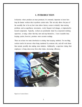
  • 1. 1 1. INTRODUCTION In factories where products are mass-produced, it's extremely important to know how long the human workers take to perform certain tasks. This not only allows the pace of the assembly line to be set, but it also allows factory owners to identify time-wasting problems such as superfluous movements, overly frequent tool changes, or impractically- located components. Typically, workers are periodically timed by a stopwatch-wielding supervisor, or using a timer that they start and stop themselves. A new wearable time- keeping system, however, promises more accurate readings. There are at least two main drawbacks to existing time-keeping methods. For one thing, workers tend to be nervous when being monitored by someone else, and will work faster than normal, possibly also making more mistakes. Additionally, a supervisor timing their employees is being taken away from other duties, decreasing efficiency. Figure no.1-sensorsleeve
  • 2. 2 2. LITERARY SURVEY In an attempt to further narrow the gap between man and machine, German tech company Fraunhofer has created a device that will measure the movements of industrial workers down to the second. Industrial manufacturers can use the device, a sleeve equipped with tiny sensors, to analyze each individual movement during assembly and ensure that not a moment is wasted. With data from sleeve movements, manufacturers should be able to minimize “impractically located components” or “overly frequent tool changes.” In other words, with a few tweaks to the manufacturing process, workers can essentially become well-oiled machines. “The present stopwatch method only allows a process organizer to time five individuals simultaneously, depending on the situation,” said Martin Woitag, research manager at the Fraunhofer IFF in a press release. “Our solution makes it possible to record time simultaneously, even at several workplaces, without requiring additional labor. The system’s greater precision and objectivity is crucial.” Inside the sleeve are three matchbox-sized sensors, each designed to record hand and arm movements from start to finish. Actions such as reaching, grasping, joining and releasing can all be differentiated. Once the manual labor is done, a PC application completes the process by calculating and reconstructing motion sequences based on the sensor data from the sleeve. Each process is then broken down into segments and relative time is established, allowing researchers to shave off the more superfluous of motions from workers’ routines. Pinpointing workers’ exact movements may be a crucial step in maximizing efficiency, but it could also be seen as a burden for employees who simply need a break every now and then. Wasted seconds, like cotton mills and mule-drawn plows, may simply be a thing of the past. At present, the sleeves can be used for assembly jobs at sitting workplaces in logistics and manufacturing. In the next stage, the researchers in Magdeburg
  • 3. 3 intend to configure the system to also analyze assembly operations during which workers stand or move around. They additionally plan to use the sensors to detect posture and thus analyze workplace ergonomics.
  • 4. 4 3. DESIGN METHODOLOGY 3.1. Block diagramand description Figure no. 2 Block diagram ACCELEROMETER*2 LCD (16*2) PULSE RATE SENSOR IR SENSOR ARM7 ZIGBEE PC (VB) ZIGBEE
  • 5. 5 ACCELEROMETER: An accelerometer is an electromechanical device that will measure acceleration forces. These forces may be static, like the constant force of gravity pulling at your feet, or they could be dynamic - caused by moving or vibrating the accelerometer. Accelerometers use the piezoelectric effect - they contain microscopic crystal structures that get stressed by accelerative forces, which causes a voltage to be generated. Another way to do it is by sensing changes in capacitance. If you have two microstructures next to each other, they have a certain capacitance between them. If an accelerative force moves one of the structures, then the capacitance will change. The capacitance is then converted into voltage. The three axis accelerometer are basically used to identify the movements across the three axis i.e. x-axis, y-axis, z-axis. Accelerometer is an electronic device which is interfaced using I2C protocol and provides the reading after every 1msec. According to the requirement of the application, the microcontroller will take the reading from the accelerometer within a fixed interval of time and do the necessary operation according to the requirement of the application IR OBSTACLE SENSOR: Here we are connecting an IR based obstacle sensor. The 50 ohm resister is used for current limiting. The current through the LED is 5v / 50 ohm = 100 mA, which is high for an LED. But to increase the range of the obstacle sensor we are using a lower range resistor (50 ohm). On the receiver side we have connected the IR receiver in reverse bias. So as soon as the light falls in the IR receiver, the anode voltage increases and when the anode voltage is more than the cathode voltage then the LED is in forward bias mode and start conducting.
  • 6. 6 PULSE RATE SENSOR: The pulse rate sensor interfaced within the system will keep on monitoring the pulses of the worker in order to ensure that the worker is in good health. If the pulse rate of the worker is fast then it will indicate that the worker is stressed and needs to be given a break. So on the basis of the output provided by the pulse rate sensor, we can track the health issues of the worker. RF Tx-Rx (ZIGBEE): Zigbee is the result of the demand from industry and consumer for wireless applications that demand for lower data rate, longer battery life, simple design, shorter range and low cost solutions. Introduction to IEEE 802.15.4 IEEE 802.15.4 is a simple standard that specifies the media access controller (mac) and physical (phy) networking layers for packet data protocol. Its license free frequency bands are: 2.4Ghz(16 channels with baud rate of 250 kps) 902 mhz - 928 mhz (10 channels with baud rate of 40 kps) 868 mhz - 870 mhz (1 channel with baud rate of 20 kps) North america, europe, australia and new zealand use the sub 1 ghz bands whereas the rest of the world uses 2.4 ghz bands. It uses carrier sense multiple access with collision avoidance for channel access. The security method used is aes-128. Have message acknowledgement and a host of other features.
  • 7. 7 Zigbee applications Zigbee technology is based on IEEE 802.15.4 industry standard. It incorporates the standard, adding the logical network, security and software to it. It supports up to 3 network topologies namely star, mesh and cluster tree. Developers need only have to focus on application while the MCU/microprocessor/RF transceiver makers and Zigbeealliance take care of the RF transmitter, RF receiver, RF channel and its protocol. There are 3 types of traffics that can be used. A) Periodic data An example of this traffic is a wireless sensor to read the water meter. The sensor is programmed to wake up at certain interval to transmit the information needed and goes back to sleep after this is done. B) Intermittent data An example of this traffic is a wireless light switch to on or off a light manually. It is triggered only by external input and hence wakes up to transmit the message to the network. When done, it is disconnected to the network and hence save energy. C) Repetitive data An example of this traffic is the security system monitoring. The devices are time multiplex to return its status to the network. This type uses more energy. There are numerous applications that can be implemented using zigbee. Amongst others are in the industry and home applications. In the industry, the applications include utility and metering where gas/water/electricity meter readings are automated and send back to utility headquarter for further action. This saves the time it takes for their personnel to come to the premises to take its reading. In
  • 8. 8 the area of warehousing/inventory management, the wireless technology will enable accurate and hassle free management of goods. Security and access control, building management system and lighting control are among the applications that can be implemented with ease. In the home, a total home automation system to control lightings, blinds, air conditioning, security system, remote control and appliances can be implemented. We are going to use ZIGBEE technology to control various electrical appliances remotely.
  • 9. 9 3.2 Hardware design and specifications MICROCONTROLLER LPC 2138  16/32-bit ARM7TDMI-S microcontroller in a tiny LQFP64 or HVQFN package.  8/16/32 kB of on-chip static RAM and 32/64/128/256/512 kB of on-chip flash program memory.  128-bit wide interface/accelerator enables high-speed 60 MHz operation.  In-System Programming/In-Application Programming (ISP/IAP) via on-chip bootloader software.  Single flash sector or full chip erase in 400 ms and programming of 256 B in 1 millisecond.  Embedded ICE RT and Embedded Trace interfaces offer real-time debugging with the On-chip Real Monitor software and high-speed tracing of instruction execution.  8-channel 10-bit ADCs provide a total of up to 16 analog inputs, with conversion times as low as 2.44 ms per channel.  Single 10-bit DAC provides variable analog output.  Two 32-bit timers/external event counters (with four capture and four compare channels each), PWM unit (six outputs) and watchdog.  Low power Real-time clock with independent power and dedicated 32 kHz clock input.  Multiple serial interfaces including two UARTs (16C550), two Fast I2C-bus (400 kbit/s),SPI and SSP with buffering and variable data length capabilities.  On-chip integrated oscillator operates with external crystal in range of 1 MHz to 30 MHz and with external oscillator up to 50 MHz.  Power saving modes include Idle and Power-down.  CPU operating voltage range of 3.0 V to 3.6 V (3.3 V ± 10 %) with 5 V tolerant I/O pads.
  • 10. 10 Figure no.3 LPC 213x LCD :- LAMPEX 16*2,BACKLIT FACILITY, TRANSMISSION CHARACTERISTICS: 1> RS 232 PROTOCOL is used for serial communication in between MCS to Zigbee. And pc to Zigbee. SOFTWARE µC programming: Embedded C
  • 11. 11 RESET DESIGN: Figure no.4- Reset circuit Reset is used for putting the microcontroller into a 'known' condition. That practically means that microcontroller can behave rather inaccurately under certain undesirable conditions. In order to continue its proper functioning it has to be reset, meaning all Registers would be placed in a starting position. Reset is not only used when microcontroller doesn't behave the way we want it to, but can also be used when trying out a device as an interrupt in program execution, or to get a microcontroller ready when loading a program. In order to prevent from bringing a logical zero RESET pin accidentally, RESET has to be connected via resistor to the positive supply pole AND a capacitor from RESET to the ground. Resistor should be between 5 and 10K and the capacitor can be in between 1µf tp 10 µf. This kind of resistor capacitor combination, gives the RC time delay for the µc to reset properly. R4 10k C7 10u 3.3V 1 2 3 4 5 6 7 8 9 10 11 12 13 14 15 16 17 18 19 20 22 21 23 24 25 26 27 28 29 30 31 32 33 34 35 36 37 38 39 40 41 42 43 44 45 46 47 48 49 50 51 52 53 54 55 56 57 58 59 60 61 62 63 64 XTAL1 XTAL2 P0.0/TxD0/PWM1 P0.1/RxD0/PWM3/EINT0 P0.2/SCL0/CAP0.0 P0.3/SDA0/MAT0..0/EINT1 P0.4/SCK0/CAP0.1/AD0.6 P0.5/MISO0/MAT0.1/AD0.7 P0.6/MOSI0/CAP0.2/AD1.0 P0.7/SSEL0/PWM2/EINT2 P0.8/TxD1/PWM4/AD1.1 P0.9/RxD1/PWM6/EINT3 P0.10/RTS1/CAP1.0/AD1.2 P0.11/CTS1/CAP1.1/SCL1 P0.12/DSR1/MAT1.0/AD1.3 P0.13/DTR1/MAT1.1/AD1.4 P0.14/DCD1/EINT1/SDA1 P0.15/RI1/EINT2/AD1.5 P0.16/EINT0/MAT0.2/CAP0.2 P0.17/CAP1.2/SCK1/MAT1.2 P0.18/CAP1.3/MISO1/MAT1.3 P0.19/MAT1.2/MOSI1/CAP1.2 P0.20/MAT1.3/SSEL1/EINT3 P0.21/PWM5/AD1.6/CAP1.3 P0.22/AD1.7/CAP0.0/MAT0.0 P0.23 P0.25/AD0.4/AOUT P0.27/AD0.0/CAP0.1/MAT0.1 P0.28/AD0.1/CAP0.2/MAT0.2 P0.29/AD0.2/CAP0.3/MAT0.3 P0.30/AD0.3/EINT3/CAP0.0 V3 RST VREF VSS VSSA P1.16/TRACEPKT0 P1.17/TRACEPKT1 P1.18/TRACEPKT2 P1.19/TRACEPKT3 P1.20/TRACESYNC P1.21/PIPESTAT0 P1.22/PIPESTAT1 P1.23/PIPESTAT2 P1.24/TRACECLK P1.25/EXTIN0 P1.26/RTCK P1.27/TDO P1.28/TDI P1.29/TCK P1.30/TMS P1.31/TRST V3 V3 VSS VSS VSS VSS RTXC1 RTXC2 V3A VBAT P0.31 P0.26/AD0.5 U3 LPC2138_SQUARE
  • 12. 12 As shown in the above circuit we are connecting an RC circuit to the RESET (pin 57) of µC .The ARM µC has an active low reset, therefore we connect an RC circuit. As shown the capacitor is initially at 0v.It charges via the supply through a 10 Kohm resistance in series, therefore the reset time of our circuit is: R*C = 10kohm * 0.1 µf = 1 msec Recommended time of reset = 1 µsec Here the RC time can vary from 10 µsec to 1 msec.
  • 13. 13 CRYSTAL CIRCUIT: Pins OSC1 & OSC2 are provided for connecting a resonant network to form oscillator. Typically a quartz crystal and capacitors are employed. The crystal frequency is the basic internal clock frequency of the microcontroller. The manufacturers make available PIC designs that can run at specified maximum & minimum frequencies, typically 1 MHz to 32 Mhz. P2 P1 P2 P1 P2 P1 P2 P1 P2 P1 P2 P1 P2 P1 State 1State 2 State 3 State 4 State 5 State 6 One Machine Cycle Figure no.5-Crystal circuit X1 CRYSTAL C9 33p C8 33p 1 2 3 4 5 6 7 8 9 10 11 12 13 36 37 38 39 40 41 42 43 44 45 46 47 48 49 50 51 52 53 54 55 56 57 58 59 60 61 62 63 64 XTAL1 XTAL2 P0.11/CTS1/CAP1.1/SCL1 P0.12/DSR1/MAT1.0/AD1.3 P0.13/DTR1/MAT1.1/AD1.4 P0.14/DCD1/EINT1/SDA1 P0.15/RI1/EINT2/AD1.5 P0.16/EINT0/MAT0.2/CAP0.2 P0.17/CAP1.2/SCK1/MAT1.2 P0.18/CAP1.3/MISO1/MAT1.3 P0.19/MAT1.2/MOSI1/CAP1.2 P0.20/MAT1.3/SSEL1/EINT3 P0.21/PWM5/AD1.6/CAP1.3 P0.22/AD1.7/CAP0.0/MAT0.0 P0.23 P0.25/AD0.4/AOUT P0.27/AD0.0/CAP0.1/MAT0.1 P0.28/AD0.1/CAP0.2/MAT0.2 RST VREF VSSA P1.17/TRACEPKT1 P1.18/TRACEPKT2 P1.19/TRACEPKT3 P1.20/TRACESYNC P1.21/PIPESTAT0 P1.22/PIPESTAT1 P1.23/PIPESTAT2 P1.27/TDO P1.28/TDI P1.29/TCK P1.30/TMS V3 V3 VSS VSS VSS RTXC1 RTXC2 V3A VBAT P0.26/AD0.5 U3
  • 14. 14 Here we are connecting twp ceramic capacitors which are basically used for filtering. In other words to give a pure square wave to the µC we are connecting the two capacitors. The basic rule for placing the crystal on the board is that it should be as close to the µC as possible to avoid any interference in the clock. POWER SUPPLY: Figure no.6 –Power Supply 5v supply design: The basic step in the designing of any system is to design the power supply required for that system. The steps involved in the designing of the power supply are as follows, 1) Determine the total current that the system sinks from the supply. 2) Determine the voltage rating required for the different components.
  • 15. 15 Figure no.7-5V DC fixed voltage regulator The bridge rectifier and capacitor i/p filter produce an unregulated DC voltage which is applied at the I/P of 7805.As the minimum dropout voltage is 2v for IC 7805, the voltage applied at the input terminal should be at least 7 volts .C1 (1000 µf / 65v)is the filter capacitor and C2 and C3 (100n f) is to be connected across the regulator to improve the transient response of the regulator. Assuming the drop out voltage to be 2 volts, the minimum DV voltage across the capacitor C1 should be equal to 7volts (at least). Power supply design of the Project : The average voltage at the output of a bridge rectifier capacitor filter combination is given by Vin (DC) = Vm – Idc / 4 f C1 Where, Vm=√2 Vs and Vs = rms secondary voltage Assuming Idc to be equal to max load current, say 100mA C = 1000 Gf / 65v , f=50hHz 19 = Vm – 0.1 / 4*50*1000*10¯6 19= Vm – 0.1 / 0.2
  • 16. 16 Vm=19.5 volts Hence the RMS secondary Voltage Vrms = Vm / √2 = 19.5 / √2 =19, 5 / 1.4421 =13.5 volts So we can select a 15v secondary Voltage In our system most of the components used require 5 V as operating voltage such as micro controller, MAX 232, MCT2E etc. The total current, which our circuit sinks from the power supply, is not more than 100 mA. We have used Regulator IC 7805 that gives output voltage of 5V.The minimum input voltage required for the 7805 is near about 7V. Therefore we have used the transformer with the voltage rating 230v-10v and current rating 500 mA. The output of the transformer is 12 V AC. This Ac voltage is converted into 12 V DC by Bridge rectifier circuit. The reasons for choosing the bridge rectifier are a) The TUF is increased to 0.812 as compared the full wave rectifier. b) The PIV across each diode is the peak voltage across the load =Vm, not 2Vm as in the two diode rectifier Output of the bridge rectifier is not pure DC and contains some AC some AC ripples in it. To remove these ripples we have used capacitive filter, which smoothens the rippled out put that we apply to 7805 regulators IC that gives 5V DC. We preferred to choose capacitor filters since it is cost effective, readily available and not too bulky.
  • 17. 17 3.3Volts design Figure no.8 Variablevoltageregulator The formula for calculating the output voltage of ARM is (As given in the datasheet of LM317) Assuming R2=470 ohms and I adj =0 then, Vout= 3.3v = 1.25v (1+R2/450) 3.3v/1.25v = (450+R2)/450
  • 18. 18 2.64* 0.45 Kohm = 0.45kohm+R2 1.18 – 0.45 Kohm = R2 R2=738 ohms Nearest value of resistance is 750 ohms Therefore with R1=450 ohms and R2=750 ohms we get an o/p of 3.3v
  • 19. 19 LCD SECTION: Figure no.9-LCD interfacing 1. LCD has 2 powersources, 1st VCC and GND are at 1 and 2 NO. Pins of LCD Used to drive the LCD 3mA current consumption. 2ndVCC and GND is at 15 and 16 NO. Pins of LCD used to drive the backlight of LCD. 100 ma current Total current consumption = 3mA + 100mA = 103 mA So, in order to reduce the current requirement we are connecting a 330 ohm resistance in series with the backlight pin VCC. This reduces the current consumption (100mA / 330ohm = 0.303 mA). Therefore new total current consumption = 0.303mA+3 mA =3.303 mA.
  • 20. 20 2. LCD data and controllines LCD has 8 / 4 data lines and 3 control lines .The 4 data lines of LCD (pin 11 to pin 14 of lcd) are connected to port 0 of the µC (0.25 , 0.26 , 0.27 , 0.28 ). The control lines are LCD RS, LCD R/W, and LCD E. In this we are connecting only 2 lines, viz, LCD E and LCD RS. The LCD RD/WR pin is grounded, since we only write into the LCD and never read from LCD. These two lines are connected to the port 0 (0.21, 0.22) of the ARM µC. The LCD RS is for selecting the data or the code register .The LCDR/W is for choosing between reading or writing on LCD. LCDE is for enabling or disabling the LCD.
  • 21. 21 Rs 232 : Figure no. 10- MAX232 IC RS 232 IC is a driver IC to convert the µC TTL logic (0-5) to the RS 232 logic (+- 9v).Many device today work on RS 232 logic such as PC, GSM modem, GPS etc. so in order to communicate with such devices we have to bring the logic levels to the 232 logic (+/-9v). Here as we can see the RS 232 chip has two pairs of TTL and 232 logic viz, Pair 1: Pin 7, 8,9,10 of RS 232
  • 22. 22 Pair 2: pin 11,12,13,14 of RS 232 We can use any one pair in our project either 7, 8,9,10 pair or 11,12,13,14 pair. if we require 2 serial ports then Depending on the requirement of the project we may have to use both the pair in the same project . The µC works on TTL logic (0-5 v).So to convert the TTL logic to 232 logic we use the 4 capacitors connected to the RS232 IC. These capacitors are called charge pumps used to convert the TTL voltage to the +/- 9 v swing required by the 232 IC. Dual Charge-Pump Voltage Converter The MAX220–MAX249 has two internal charge-pumps that convert +5V to ±10V (unloaded) for RS-232 driver operation. The first converter uses capacitor C1 to double the +5V input to +10V on C3 at the V+ output. The second converter uses capacitor C2 to invert +10V to -10V on C4 at the V- output.
  • 23. 23 3.3PCB Designand layout Figure no.11 PCB layout Layout basically means placing or arranging things in a specific order on the PCB. Layout means placing of components in an order. This placement is made such that the interconnection lengths are optimal .At the same time, it also aims at providing accessibility to the components for insertion testing and repair.
  • 24. 24 The PCB layout is the starting point for the final artwork preparation layout design should reflect the concept of final equipment. There are several factors, which we must keep in mind for placing the layout. Schematic Diagram: The schematic diagram forms main input document for preparation of the layout. For this purpose the software for PCB design, ORCAD was used. Electricaland thermal requirement: The PCB designer must be aware of the circuit performance in critical aspects of the same concerning electrical conditions and the environment to be used in. Mechanicalrequirement: The designer should have the information about physical size of the board, type of installation of board (vertical/horizontal). The method of cooling adopted, front panel operated components etc. Component placing requirement: All components are to placed first in a configuration that demands only the minimum length for critical conductors. These key components are placed first and the others are grouped around like satellites. Components mounting requirements: All components must be placed parallel to one another as far as possible .i.e. in the same direction and orientation mechanical over stressing of solder should be avoided. Layout Methodology: For proper layout design minimal steps to be followed are: 1. Get the final circuit diagram and component list. 2. Choose the board types, single sided / double sided / multilayer 3. Identify the appropriate scale for layout. 4. Select suitable grid pattern. 5. Choose the correct board size keeping in view the constraints. 6. Select appropriate layout technique, manual / automated. 7. Document in the form of the layout scale.
  • 25. 25 Art Work: Art work is accurately scaled configuration of the printed circuit from which the master pattern is made photographically. Art Work Rule: Rules followed while selecting artwork symbol takes: 1. Minimum spacing between conductor and pad should be 0 / 35 mm in 1:1 scale . 2. Minimum spacing between parallel conductors should be 0.4 mm in 1:1 scale. 3. The area of non-PTH solder pad should not be less than 5 sq.mm. 4. The width of current carrying conductors should be determined for max..temp. rise of 20 ْC . GeneralArt Work Rules: When there is higher conductor density assumes the conductors parallel to any one of the edge of the board. When conductors have to be placed in other direction preference should be given to the 45ْ direction or to the 30ْ / 60ْ direction. Whenever there is sufficient space available the conductors can be run in any direction so as to achieve sorted possible interconnection. As far as possible, design and the conductor on the solder pad. Conductor forming sharp internal angles must be avoided. When a member of conductor has to run between two pads the conductor lines are run perpendicular w.r.t. the center-to-center line of pair of pads. Equally distributed spacing is to be provided when three or more conductors run along a direction and / or between two pads. Minimum spacing is provided when three or more lines run along a direction and / or between two pads. The diameter of solder pad should be approximately 8 times the drilled hole diameter.
  • 26. 26 SOFTWARE DESIGN The Project team is meeting once a week to discuss the progress made by each member and to share the relevant information and be documents that have been prepared. The Number of meetings may increase during the final semester as the team members will have more time. The major milestones to be achieved are as follows:  Results of research of existing system and discussions with the Project leader.  Results of interview with experts and team meetings to finalize the requirements of the software.  Results of the Design Phase, which include a number of modeling diagrams, like the use cases, class diagrams, etc.  Results of the first coding phase will be an initial code that will be then tested.  Based on the results of the testing, they code will be reviewed in the second coding phase.
  • 27. 27 Accelerometer: A Select ADC0 Ch1 Read ADC Store and display X axis on LCD Select ADC0 Ch2 Read ADC Store and display Y axis on LCD Select ADC0 Ch3 Read ADC Store and display Z axis on LCD Compare the acc. Y axis reading with set points Is Movement detected? DA YES A
  • 28. 28
  • 30. 30 LCD ARM: Initialize LCD Start IODIR0 |= 0x1E600000; //0001 1110 110 (1E6) // D4 to D7 RS E //Initialize LCD using set commands LCD_Function(0x28); //Data length = 4bit,Number of lines = 2 , Font = 5*7 LCD_Function (0x0C); //Display ON , Cursor off , Blink Off LCD_Function (0x06); //Set cursor direction ON LCD_Function (0x01); //Clear display Is End of conversion detected? Stop
  • 33. 33 UART: A Is serial interrupt detected? A A Is serial Interrupt = RLS A Is serial Interrupt = IIR_CTI A Is serial Interrupt = IIR_THRE A Is serial Interrupt = RDA B NO YES YES YES YES NO NO NO NO
  • 34. 34 TESTING AND RESULT PROTEUS The PROTEUES is an editor, which is easy-to-use, yet powerful tool for designing printed circuit boards (PCBs). It is a complete platform for the development of any type of complicated sophisticated multilayered PCBs. This software consist of the following tools  Schematic Editor In this one can develop design circuits for the required PCB.  Layout Editor In this one can develop design actual PCB structure required. This is done automatically by the software using the circuit in the schematic editor itself.  Library Editor This is very useful in case of customized component design that does not occur in the predefined library according to our need.  Auto Router This is an artificial intelligence based tool or subroutine that can do auto routing of the PCB tracks designed.  Cam Processor This is used to finally print the various layers of the designed PCB viz. Top Layer, Bottom Layer, Component Layer, Masking Layer etc.
  • 36. 36
  • 37. 37 CONCLUSION Advantages  Less time delays  Quick response time  Fully automated system  Low power requirement  Robust system  Cost effective  High reliability  Good stability Applications  In factories where products are mass produced  To monitor the stress levels and health of workers Conclusion By using this intelligent sensor sleeves the efficiency of the workers would increase thereby increasing the production efficiency of the factory. The supervisor of the workers can get the data on a remote computer and will be able to devote his time to other responsibilities. This project follows the spirit of F.W.Taylor’s theorem of scientific management.
  • 38. 38 FUTURE SCOPE  It can be expanded to identify best practices and eliminate movements that could lead to injury.  It can be used as a data gathering exercise for robotic arm manipulators.
  • 39. 39 REFERENCE Books:  ARM System Developer's Guide: Designing and Optimizing System Software April 8, 2004by Andrew Sloss (Author), Dominic Symes (Author), Chris Wright (Author)  Blackbook of embedded system.  The 8051 Microcontroller and Embedded Systems (2nd Edition) by Muhammad Ali Mazidi, Janice G. Mazidi and Rolin D. McKinlay  ARM System-on-Chip Architecture (2nd Edition) August 14, 2000 by Steve Furber (Author) Webpages: LCD 16*2:  www.engineersgarage.com/sites/default/files/LCD%2016x2.pdf  www.electro-tech-online.com/datasheets.../40487-2-16-dot-matrix-lcd-datasheet  www.datasheetcatalog.com/datasheets.../-/LCD-016M002B. RS232:  www.datasheetcatalog.com/datasheet/M/MAX232.shtm  www.camiresearch.com/Data_Com.../RS232_standard.html  www.arcelect.com/rs232.htm
  • 40. 40 APPENDIX A- Circuit schematic Figure no. Circuit diagram
  • 42. 42 LIST OF FIGURES Serial no. Name of figure Page no. 1 Sensor sleeve 1 2 Block diagram 4 3 LPC 213x 10 4 Reset circuit 11 5 Crystal oscillator circuit 13 6 Power Supply 14 7 5V DC Voltage Regulator 15 8 Variable Voltage Regulator 17 9 LCD Interfacing 19 10 MAX 232 IC 21 11 PCB Layout 23 12 Accelerometer 27,28 13 ADC interfacing with ARM 29 14 LCD interfacing with ARM 30 15 Pulse Rate 31 16 Timer Interrupt 32 17 UART 33 18 Result 35,36 19 Circuit diagram 39