SlideShare ist ein Scribd-Unternehmen logo
1 von 136
The Big Picture 3
DAS 3
NAS 3
Disk Array 3
Tape Libraries 3
Storage Array 4
Storage Area Network SAN 4
Disk (DL) and Virtual Tape Libraries (VTL) 5
IP Storage 5
Content Aware Storage CAS 5
ILM Information Lifecycle Management (ILM) 6
Communication 6
Directional Transmission Modes 6
The OSI Model 7
Data structures 8
Cyclic Redundancy Check (CRC) 10
DATA vs INFORMATION 10
Times Impacts 11
The SNIA Shared Storage Model (SSM) 15
Port Types include: 16
Storage Arrays 19
BROCADE 20
CISCO 30
EMC 31
EMC COMMANDS 38
HITACHI 61
HP 3PAR 66
IBM 78
DSC8000 78
SVC V7000 79
NETAPP 80
NETAPP COMMANDS 82
General Commands 82
Diagnostics 82
Software 82
Root Volume 82
Aggregates 82
Volumes 83
Qtree’s 83
Snapshots 83
SnapMirror 83
Cluster 84
Autosupport 84
Hot Spares 84
Disks 84
Luns 85
Fiber FCP 85
iSCSI 85
Cifs 85
NFS 86
HTTP Admin 86
SIS (Deduplication) 86
User Accounts 86
DNS 87
Logging 87
Network 87
OS COMMANDS CHEAT SHEET 112
The Big Picture
DAS
Early mainframe systems used several techniques to manage VD wait and move control away
from the CPU. Imagine the motherboard of a personal computer with a special connection to
extend the bus outside of the case. Called the channel, this path provided the necessary link
between the CPU and its peripheral equipment. lt was expensive. Management of disk requests
moved from the CPU to the self-contained [lO controller, now attached to the channel. A similar
approach called front-end processor,managed network connectivity. These techniques offloaded
the I/O workload from the CPU and more effectively managed the wait for completion of
outstanding requests through cache. While mainframe is not a subject area for this course, the
concept of a controller is a recurring pattern in the storage infrastructure.
Later techniques connected multiple disks to the same bus and transferred control into the disks.
This allowed each disk to work independently, in parallel, instead of sequentially. In early personal
computing the interface limit was two disks, each clamped on a ribbon cable bus. Enterprise
computing often used the Small Computer Systems Interface, known as SCSI (pronounced
skuzzy). SCSI gave the appearance of a connection string, although internally it was a bus. a bus
with higher attachment limits; each disk has an address describing its logical position on the bus.
The physical number of wires in the bus limited the count of available addresses. Address limits
are a pattern. Even today, the logical address limits can vary from the standard.
NAS
As networks emerged and stabilized, it was not enough that we could move data or files on the
network; it was inconvenient and had serious limitations. File sharing emerged as a way to make
information available to multiple hosts, simultaneously. Storage. connected to a single host,
became available to other hosts through the network. The special software served files to clients in
response to their requests. The NAS device became a centralized repository for shared
documents. At other hosts, known as clients. the remote files appear to be local. The abstraction
simply made the files available. Later, this concept gained the title: Network Attached Storage, also
known as NAS. Officially, a NAS device is a dedicated file server, optimized for the task of serving
files, often, without the ability to be a general-purpose server. File serving and NAS devices are
both patterns.
File sharing services and specialized NAS devices are very common. lt would be difficult to size
the total market because the techniques are in many places. My personal favorite is a sea floor
sensor robot that is a client to shared directories in land-based systems where many robots store
reports of water current, temperature, waves and other readings for analysis. Robot NAS users.
Disk Array
The combination ofJBOD with an embedded controller is the earliest form ofa disk array. A disk
array is a set of one or more commonly addressable disk subsystems, combined With a body of
control software. The control software presents the disks’ storage capacity to one or more hosts as
one or more virtual or logical disks, similar to the volume manager software that ran on the hosts.
The control software also includes techniques to protect the data from single disk failure and
improve performance.
Tape Libraries
Tape libraries evolved as common enclosures around one or more tape transports. T he name is
an illusion to the books on shelves found in a library. They include common power. tape storage
and media handling devices. Larger versions include many drives, extensive media storage and
complex shared robotics. Unlike the controller in a disk array, the controller in a tape library
focuses on media and robot management rather than performance and protection. Most rely on
host control software to manage I/O. Protection usually means tape copies. controlled by a host
with added integrity checks that are part of the tape transport or the duplication software. Some
new forms include disk and tape under the same controller. The term tape array is a more proper
description, but less commonly used.
Storage Array
The phrase Storage Array emerged as a collective term to describe a disk array with enhanced
capabilities. Unlike a group of separately managed disk arrays, a storage array provides common
management and shared access to a collection of one or more disk arrays, referred to as the
aggregated storage elements. In almost every vendor, cache algorithms adapt to use access
patterns to reduce I/O wait for read and write requests. Some of the special services include local
and remote replication. snap, and secure delete. New services tend to start here and are later
move down to disk arrays.
The informal array classes include frame, modular and mid-tier. The largest frame arrays include a
cabinet of controller electronics and supporting cabinets to hold over a thousand disks. This gives
you an internal capacity of over 500 terabytes. Few need that much storage, however the
construction of frame arrays offers the best resiliency. As a result, they are at the enterprise core.
Mid-tier arrays are more practical through 80 or 90 terabytes, at lower cost; making them the
growth area of the industry. Many enterprises surround the core with mid-tier to reduce cost. Three
more patterns.
Storage Area Network SAN
Storage Area Networks (SAN) give us the ability to move data between the computer systems and
storage elements. and among the elements without direct physical paths. A SAN is most often a
switched communications infrastructure. It provides physical connectivity and a management layer
to organize the connections, storage elements and computer systems so that data transfer is both
secure and robust. We loosely think of DAS and SAN as moving blocks of data. In contrast. we
thing of NAS as moving whole files. Many people believe that the term SAN is a synonym for Fibre
Channel technology. Yet, the pure definition suggests that any form of network whose primary
purpose is to “provide access to storage elements" is a SAN. In addition. a SAN does not need to
be switched; it just needs to be a network.
We use the term Fabric to bring focus to the switch interconnections. The fabric exists between
any two ports connected to end devices. called nodes. A node can be any device that is not a
fabric device. The fabrics’ purpose is to transmit data between nodes. The path is a virtual
channel. Therefore, the SAN is the entire environment and the fabric is a subset. Having a
switching fabric is a big benefit because it solves many connectivity problems. Giving access to
any attached resource, it allows placement of equipment where it makes the most sense, and
establishes a consistent connectivity pattern. The typical pattern is point-to-point, from a node to
the fabric.
The fabric takes care of the rest. Fabrics do have cost. but the benefits outweigh the cost in many
scenarios.Convenient access to resources makes the fabric very practical. Consider a remotely
managed data center. You can add disks to a server, bypass a failing tape drive and add or
replace a server without the physical presence of a single person in the data center; you just need
properly connected devices.
Fabrics make it possible to consolidate and centralize resources. However, some people take the
approach a bit too far. They ignore the network 80/20 rule that 80% of all traffic is local. It is still
important to use good judgment when placing physical resources. Storage devices are less
forgiving. but are more tolerant of single bit errors than say Web or IP based connections.
However, given guaranteed. high-speed network facilities, it becomes possible to link the
fabrics. Once the link is in place. you can access remote resources. Perhaps you want to copy a
tape from the local tape library to the remote library. meeting a legal or insurance requirement to
store backups in a distant location. By using the extended fabric, you will not worry about the tape
will falling off the back of a truck. causing the company to be in the headlines for losing personal
information.
Disk (DL) and Virtual Tape Libraries (VTL)
Disk (DL) and Virtual Tape Libraries (VTL) use disk array technology for backup and recovery. VTL
is the most popular approach. ln a VTL. the disk array appears to be many tape transports, using
disk space to create many virtual tapes. The sizes of the virtual tapes are similar to real tape.
Because it uses a common tape metaphor, it is easy to setup and use, in addition, it easy to copy
from virtual to real tape. In contrast, the disk library looks like a big disk, and the backup is just a
file on disk. In both cases, recovery of independent data from the disk is much faster because it
does not have to load or move tape. File access within the backup virtual tape or backup file is just
a bunch of pointer and offset arithmetic. However, the time for a lull recovery varies too much to
make a performance statement. it may be better, worse, or the same. We can meet disaster
recovery requirements by copying the backup blocks in the library to a remote location. In addition,
a new technique called data de-duplication reduces total requirements while increasing the number
of recovery points.
IP Storage
IP Storage allows hosts to connect to disk and tape via the TCP/IP protocol. Variants allow Fibre
channel extension services. The concept that “any network whose primary purpose stop access
storage elements qualifies as a SAN”, is more difficult when we consider IP based storage. lt is
Similar to in that its primary fabric is the internet. It is different in that IP Storage moves blocks and
NAS move files. NAS is not in the category of SAN. it certainly is not a fabric, and you cannot find
a box called a NAS switch. IP Storage, although sharing networking resources with other kinds of
traffic, appears to be a fabric, a virtualized fabric within the internet, and for that reason, it loosely
qualifies as a SAN.
A less pure. view is that IP Storage is hybrid technology at a great price point. Many vendors
released IP Storage with embedded aggregation, virtualization and services that work well With
inexpensive disk. Some vendors only added IP Storage under duress, because end-users put an
ISCSI check box on their RFP`s. However, it offers new fabric options, including connection on IP
or Fibre Channel or both with known patterns. Now that people have tried it, they are using it more.
IP Storage is an Important technology that will change the face of storage infrastructure.
Content Aware Storage CAS
Another set of emerging technologies includes Object Storage Device (OSD) and Content Aware
Storage (CAS). While different in execution. they both challenge the notion that a computer needs
to know where the blocks are stored. When you store data using either technology, these deVices
return an object identifier and perform all the tasks of finding blocks without burden to the host
operating system. When you want to retrieve data, you provide the identifier. This is a transfer of
control from the operating system into the storage. The OSD side is hardware aware, implemented
in the storage layer and the CAS side is software aware. implemented in a controller. In CAS and
OSD, both can set metadata flags to render a file immutable (i.e., un-erasable) for a unit of time, or
set a flag to encrypt the file on disk without using compute cycles for the calculations. These are
just two possible functions. OSD is block based. built within IP Storage. CAS is IP network based
and may appear as a file based technology. They are useful for meeting regulatory compliance
making them of much importance today.
ILM Information Lifecycle Management (ILM)
ILM Information Lifecycle Management (ILM) is one of the buzzwords of the storage industry
today. It is both a concept and an emerging technology. The concept existed for a very long time.
Yet, the technology is only emerging. This paradigm causes confusion, but at least it now has a
label.
On first glance at the big picture, you see all of the technologies we just considered and you realize
that many parts were missing. Then look at it again, and awareness comes over you that those
parts only exist to meet requirements.
Communication
Communication, at its most human form, is the process of exchanging ideas and information. We
exchange them by the written word, speech and signaling. It is an active process. The process
involves the encoding, transmitting, and decoding of messages. Messages are the object of the
exchange.There are many means of communicating and many different language systems. Yet
speech and language is only a portion of our exchange. Other aspects of communication may
enhance or even eclipse the linguistic code. These aspects are paralinguistic, nonlinguistic and
metalinguistic. paralinguistic mechanisms signal attitude or emotion and include intonation, stress,
rate of delivery, and pause or hesitation. Nonlinguistic clues include gestures, body posture, facial
expression, eye contact, head and body movement, and physical distance or proxemics.
Metalinguistic cues signal the status of communication based on our intuitions about the
acceptability of utterances. In other words, metalinguistic skills enable us to talk about language,
analyze it, think about it, separate it from context, and then judge it.
The process has three stages, encode, transmit and decode.
• Encode: In a digital sense, the encoding process converts binary data into the signals
appropriate for transmission across a communications channels. Often, the process
encapsulates the message in a frame (the envelope), along with a code to check for errors in the
message, on receipt. If privacy is a concern, we may encrypt the message.
• Transmit: The transmission channel works within a set of behavioral algorithms, message
formats and message semantics used to support communications between the entities across a
network.
• Decode: On receipt, the decoding process converts the signals received from the signaling of the
communications channel to the binary data of the end-point.
Expectation It is a reasonable expectation that the delivery of the message will be without
alteration, in a predictable time to the intended recipient. In addition, the user expects transparent
processing, i.e., they do not need to know how the network does it, just, that the message will
arrive. Metadata Not all messages represent content. Some messages contain control information
or data about the data. They may be just as important, if not more important than the original
message.
Directional Transmission Modes
In traditional data communications, we say that there are three (3) directional transmission modes:
simplex, half-duplex and full duplex. Used in a storage sense, the latter two of these patterns
describe the way that we connect our storage to a host. Knowing the difference will help you to
know the potential bandwidth between two points.
Simplex transmission is in only one direction between sending and receiving nodes. It is similar to
a one-way street. Typical examples include broadcast transmission from radio, television or
satellite sources. Generally, the receivers are unknown; however, they know the transmission
frequency.
Half-duplex transmission, also known as “HDX”, is the ability of a transmission facility to transport
data in both directions, but not simultaneously on the same link. A half-duplex facility uses some
form of Request-to-Send (RTS) and Clear-to-Send (CTS) to manage transmission direction. For
example, a half-duplex, 100-megabyte (100 MB) connection has 100 MB of bandwidth.We
associate half-duplex with a shared transmit and receive connection.
Full-duplex transmission, also known as “FDX” is the ability of a transmission facility to transport
data in both directions, simultaneously. A full-duplex facility, also known as the link, typically
contains two unidirectional channels, transmitting in opposite directions. Effective bandwidth
doubles because the facility can send and receive over the same link. For example, a full-duplex
100-megabyte (100 MB) connection has 200 MB of bandwidth. We associate full duplex with an
independent transmit and receive connection.
The OSI Model
What is OSI? The OSI Reference Model describes the functions and interfaces that enable
computers to communicate with each other. There are seven (7) functional layers in the model.
Each layer is a group of related functions that provide services to the layer above. while receiving
services from the layer below. For any layer there is only a need to know the interface protocol of
the adjacent layers and of no others. In current practice cross-layer optimization breaks the
boundaries, however the functions remain. Published in 1984 by the International Organization for
Standardization (ISO), it remains the primary reference for communication protocol design. Why?
Because it is a layered architecture, with ordered functionality and defined interfaces that we
combine to meet our purposes.
Relevance: Many of the concepts and terms of OSI are common to other forms of networking,
including storage networks. The unique nature of storing data requires variance from the model,
yet the terms remain Within storage specifications. However, you need to take care as some
storage terms have context sensitive use that differs from 081. It is a good place for us to start in
the study of storage protocols. The following list outlines the seven layers of the OSl model.
Layer 7 The Application Layer
Provides networking services to user-defined applications or process and it issues requests on
their behalf to the presentation layer. It serves user interface functions for programs like telnet,
HTTP and SMTP; however, it is not a human interface. For example, an e-mall program is
above this layer. When we write an e-mail and hit send, this sublayer provides the functional
elements that takes data from the program and prepares it for placement on a network.
Layer 6 The Presentation Layer
PRovides formatting services to the application layer. It establishes context between application
layer entities while encapsulating Presentation Service Data Unit into Session Protocol Data Units
and moving them down the stack. Higher-layer entities may use different syntax and semantics, as
long as this layer understands both entities, and the mapping between them.
This layer seems confusing on first read. A way to think of the formatting services is like a human
translator. The person hears the words and loosely converts words from one language to another
Within a context of cultural knowledge. This results in equal meaning, preserving the message. For
example, if the source computer sends a JPEG, and the destination computer needs a GIF, this
layer would reformat the presentation. In this case, the mapping is loose. It is important to note that
there is no rule that translation occurs in the sender or receiver. Other user interface functions that
are more rigid include character set conversion, e.g., ASCII to EBCDlC, serializing objects and
other data structures into and out of XML, and cryptographic encoding rules to allow end-to—end
encryption in this layer.
Layer 5 The session layer
Manages connections between hosts. If an application on one host needs to talk to an Session
application on another, the application layer sets the connection up and ensures resources are
available to facilitate the connection. You need all three layers to do the setup. Network people
tend to refer to Layers 5-7 collectively as the application layers.
Layer 4 The transport layer
Is responsible for taking the chunk of data from the application and preparing it for Transport
shipment or placement on the network. Prepping data for transport involves chopping the chunk
into smaller pieces and adding a header that identifies the sending and receiving applications
(otherwise known as port numbers). Each piece of data and associated headers is called a packet.
Content switches operate at this level.
Layer 3 The network layer
Is responsible for adding another header to the front of the packet, which identifies Network the
unique source and destination address. The process of routing IP packets occurs at this level.
Layer 2 The data link layer
Is responsible for adding another header identifying the particular Layer 3 protocol Data Link used
and the source and destination hardware addresses (also known as Media Access Control
(MACAddresses). At this point, the packet is complete and ready to go onto the network. Ethernet
switching and bridging operate at this level.It is important to appreciate that the data link layer
includes several functional components that include:
• Error Control
• Flow Control and
• Connection Management
Layer 1 The physical layer
Is responsible for converting the packet into binary signals to be transmitted over Physical the
network. The actual physical network can be copper, fiber, or wireless radio frequency. This layer
also provides a method for the receiving computer to validate that the data was not compromised
during transmission.
The combination of the seven layers is often called a stack. A transmitting workstation traverses
the stack from Layer 7 down to Layer l, converting the application data into network signals. The
receiving workstation traverses the stack in the opposite direction: from Layer 1 to Layer 7. It
converts the received transmission back into a chunk of data for the running application.
Each layer of the OSI model uses its own protocol to communicate with its peer layer in the
destination device. The OSI model specifies how each layer communicates with the layers above
and below it, allowing vendors to focus on specific layers that work with any other vendor’s
adjacent layers.
Data structures
Data structures enable the network to use, store and transmit data efficiently. They evolved to be
the most efficient algorithm within the context of the messages they expected to transmit and the
network they would traverse. The choice of data structure often begins from the choice of an
abstract data structure. Then, they evolve over time as the context and network changes. Our well-
designed data structures, allow for performance of critical operations in the process of transmitting
data.
A message is an object of communication. It is something, which provides information; it can also
be this information itself. In this case, the meaning is dependent upon the context in which it is
used; the term may apply to both the information and its form.
More precisely, in the communication science, a message is information, sent from a source to a
receiver. Some common definitions include:
• Any thought or idea expressed briefly in a plain or secret language, prepared in a form suitable
for transmission by any means of communication
• An arbitrary amount of information with a defined or implied beginning and end
• Record information, a stream of data expressed in plain or encrypted language (notation) and
prepared in a format specified for intended transmission by a telecommunications system
Note that the message is not necessarily the payload. The payload or mission bit stream is the
data, such as a data field, block, or stream, being processed or transported the part that
represents user information and user overhead information. It may include user-requested
additional information, such as network management and accounting information. In addition, the
payload does not include system overhead information for the processing or transport system.
Finally, owing to size, a message may be broken into multiple payloads.
Segmentation has several contexts. In the context of a message, we recognize that the size of a
message may be larger than the maximum payload size of a packet. In a single network with
known maximum packet size, the transport layer protocol can immediately divide, segment or
fragment, larger messages into smaller units for transfer cross the network. In the case of internets
comprising networks with varying maximum packet sizes, however, either the minimum packet size
must be known; otherwise, the end-point will default to the local maximum. If it is not known, then
the network layer in each end and intermediate system must perform the necessary segmentation
(fragmentation) and reassembly operation. The first alternative will result in some networks in the
path being used inefficiently,while the second requires an additional function to be performed by
the network layer.
Note that we use the term segment in the context of the original message being split into smaller
units, while we use the fragment in the context of a packet being remade into smaller packets. The
term segmentation is also used in the context of network, to split or isolate a network workload.
A packet is the fundamental unit of information carriage in all modem computer networks. The
packet is a formatted block of data carried by a computer network. Networks that do not support
packets, such as traditional point-to-point telecommunications links (not to be confused with other
point-to-point circuits); simply transmit data as a series of bytes, characters, or bits alone. When
data is formatted into a packet, the network can transmit longer messages more efficiently and
reliably. The term datagram is sometimes also used, and in some contexts its meaning is subtly
different from packet.
A packet consists of two kinds of data, protocol control information (PCI) and user data, also
known as the payload. PCI carries information about the user data, such as source and destination
address, error detection codes, like checksums, and sequencing information. Typically, PCI is
found in packet headers and trailers, with payload placed in between.
Packet vs Datagram
In general, the term packet applies to any message, formatted as a packet, while the term,
datagram is generally reserved for the packets of an unreliable service. A reliable service is one
where the user is notified if delivery fails. An unreliable service is one where the user is gm notified
if delivery fails. For example, IP provides an unreliable service. TCP uses IP to prove a reliable
service, whereas UDP uses IP to provide an unreliable service. All these protocols use packets,
but UDP packets are generally called datagrams.
When a network does not guarantee packet delivery, then it becomes the host’s responsibility to
provide: reliability by detecting and retransmitting lost packets. Our experience during the early
days of the internet indicated that the network itself could not reliably detect all packet delivery
failures. As a result, the responsibility for error detection was pushed on the sending host, i.e. was
the message received, if not, retransmit. This led to the “end-to-end” principle, which is one of the
Internet`s fundamental design assumptions.
Whenever possible, communications protocol operations should be defined to occur at the end-
points of a communications system, or as close as possible to the resource being controlled.
Cyclic Redundancy Check (CRC)
To assure that the message sent is the message received, at a minimum, packet based network
protocols implement a cyclic redundancy check (CRC). The term CRC is often used to denote
either the function or the function's output. A CRC can be used in the same way as a checksum to
detect accidental alteration of data during transmission or storage. CRCs are popular because they
are simple to implement in binary hardware, are easy to analyze mathematically, and are
particularly good at detecting common errors caused by noise in transmission channels.
A CRC is an error-detecting code whose computation resembles a long division computation in
which the quotient is discarded and the remainder becomes the result, with the important
distinction that the arithmetic used is the carry-less arithmetic of a finite field. The length of the
remainder is always less than the length of the divisor, which therefore determines how long the
result can be. The definition of a particular CRC specifies the divisor to be used, among other
things. Although CRCs can be constructed using any finite field, all commonly used CRCs employ
a finite field, the field of two elements, usually called 0 and l, comfortably matching computer
architecture. We will only discuss binary CRCs, but the principles are more general.
CRCs are not, by themselves, suitable for protecting against intentional alteration of data (for
example, in authentication applications for data security), because their convenient mathematical
properties make it easy to compute the CRC adjustment required to match any given change to
the data.It is important to understand that while useful for error detection, CRCs cannot be safely
relied upon to verify data integrity fully in the face of intelligent (rather than random) changes.
Novices sometimes assume that a CRC can guarantee verify data integrity; their reasoning
suggests that:
if a message and its CRC are encrypted then transmitted over an insecure channel on receipt,
decrypt check that decrypted CRC matches the decrypted message then the message cannot
have been altered in transit
SAN protocols use CRC mechanisms. However, SANS go further, using 10-bit bytes with
embedded parity in addition to CRC. This technique allows Fibre Channel to recover from single bit
errors using the CRC to validate the correction. In a typical Ethernet based network, a single-bit
error would require retransmission“. Under increasing load, such a network would experience more
retransmission, which in turn would further increase load, at some point creating an avalanche.
The SAN protocol authors recognized the impact of retransmissions and opted for an approach
that made the protocols’ performance more predictable under load. The disk drive industry also
uses variants of these techniques.
DATA vs INFORMATION
There is a big difference between the terms data and information. Many people use them
incorrectly, because they believe that they are interchangeable. Care in using these terms will help
you to consistently describe storage technologies.
Data is a grouping of bits and bytes that may contain an individual fact or multiple facts, or a value,
or a set of values, but they are not significant in and of themselves because they are without
context.
Information has context. Context converts data into information. Without context, the data is
useless to the owner. When storing data on paper forms, the forms have headings to give meaning
to the data. In the past, we would file the forms in folders and drawers and cabinets, each with
labels. Today, we preserve these approaches in windowing and database metaphors using data
structures, directories and file names.
Times Impacts
We are always waiting for a response from the system, even in a system that is close to perfection.
All architectures are a collection of time impacts. Understanding their sources and limits is key part
of all storage and systems work. The measures of delay, latency, and response time are often
overlooked; however, they are very important because the cost of improving them is a function of
the value we place on performance, from either the end-user or the machine’s perspective.
Latency is the delay induced by the physical structure of a device or process. ln the case of a
medium such as fiber or wire, the limit is the speed of light. We cannot make light faster; therefore,
the latency is a function of length and is predictable.
Unlike latency, delay varies according to the time spent in queue. An overloaded device at any
point, end-to-end can induce delay, and that delay may be unpredictable.
Response time is one of the most important storage performance metrics, denoting the time it
takes to finish a given storage operation. The operation could be defined as any of these storage
operations: read, write, open, close, search, etc. The response time is measured from the initiation
of the operation(request) to the completion of the operation (reply.) End-to~end measurement is
most important, and includes all times of all components. Often, response time is graphed against
throughput in IOPS.
Response time is a range of time (measured in milliseconds) where each response to the
corresponding request must fall. The appropriate range is a defined metric between lT and the
user of the system. It is specified in a Service Level Agreement (SLA) typically measured from the
perspective of the end-user. A failure to meet the SLA occurs if a specified percentage of requests
fall outside of the stated range over a specified time. Remediation may require an adjustment in
workload or the infrastructure.
Utilization is the fraction of time that a resource (channel or device) is busy. It is expressed as a
fraction of the resources total capacity. Utilization has a direct impact on response time. For
example: an increase in utilization results in an increase in response time, approaching infinity as
utilization approaches 100% and a decrease in utilization results in a decrease in response time,
approaching the standard, no load, service time. This is true in a system based on random arrivals.
Value
Perhaps you want to play a game that requires you to reboot your workstation. If there was
something that you could do to make the workstation reboot more quickly, then you could get back
into the game more quickly. The personal effort and/or components required to reduce reboot time
have cost, however, that cost may be offset by the value you place on gaining more game time. In
a similar way, changes in these time impacts have value when a business owner can see a
financial benefit by using better or additional components and/or architectural changes.
Combining these thoughts, latency is often internal to components, a function of distance or
architectural design limit, and is difficult to change unless we use higher quality components,
reduce distance or change the architecture. However, we can reduce delay by providing more
queues and simultaneously decrease response time by lowering utilization. As you can see,
managing time, i.e., performance is both art and science, limited by value.
Bandwidth is the total amount of data transferred through a system or medium over a unit of time,
also known as data transmission rate. Bandwidth is often described using two different levels:
Raw bandwidth or line-speed is the specified transmission rate of a component. A transmission
line or bus will have a physical signal rate that determines the maximum possible data rate. The
user guarantee is not to observe anything faster than this specified rate.
Sustained bandwidth is the data rate after accounting for all the overheads that might be needed
for the transmission operations. The sustained bandwidth will always be less than the raw band-
width if the transmission medium has contention or if parts of the transmission are not considered
usable data. Sustained bandwidth is a better representation of the performance a user observes
when using the component. Tradition requires use of upper case “B” for bytes and lower case “b”
for bits.
The bit rate is the number of bits that are moved or processed per unit of time. It is inclusive of the
useful data as well as the protocol overhead. In contrast, the net bit rate, useful bit rate or
information rate excludes the physical layer protocol overhead, but generally, not the network layer
protocol overhead.
Throughput is an average of the amount of work performed by a component or system over a unit
of time. Throughput is generally expressed in operations per second, transactions per second or
bytes (of useful data) per second. Although throughput and bandwidth are sometimes used
interchangeably, there is a fundamental difference. The difference stems from the fact that
operations reported in the throughput can have different data sizes. This affects the bandwidth
directly; therefore, we need to understand the impact of block or transaction size on actual
throughput. We know in the case of hard drives, low block size yields higher lOPS but
exponentially lower throughput.
ln a network, throughput often excludes data link layer protocol overhead and sometimes network
layer protocol overhead. It is not an instantaneous measure, but rather a long-term average
measured at a reference point below the network layer and above the physical layer.
The maximum theoretical throughput is the maximum possible quantity of data that can be
transmitted under optimal circumstances. lt is similar to, but usually lower than channel capacity.
Channel capacity is the upper limit of the amount of information that can be transmitted over a
communications channel, reliably.
IOPS l/O´s per second are a measure of performance for storage devices. Unlike bandwidth, it
represents the number of exchanges with a device at a specific block size. Bandwidth is
approximately equal to request size * lOPS. If a device makes a claim to be capable of a maximum
number of lOPS, the claim should include the block size, random or sequential requests and cache
hit ratio; if unstated assume the lowest block size at 100% cache hit-ratio.
Availability is the proportion of time that a Customer is able to access a particular service. The
measure of availability is from the Customer’s point of view. Availability depends on:
• Reliability of components
• Resilience to failure
• Quality of maintenance and support
• Quality of operating procedures
Reliability of a service is determined by the amount of freedom from operational failure. Reliability
can further be defined as the ability of components to perform a required function under stated
conditions for a stated period. Measurements of reliability include:
• Mean Time Between Failures (MTBF)
• Mean Time Between System Incidents (MTBSl)
• Number of breaks per unit time (period)
• Resilience built into the service
• Preventative maintenance applied (assumed, but measured)
Serviceabilityis the ability of external suppliers to meet the contractual conditions regarding
reliability, maintainability and maintenance support of components.
Security Availability Management is closely related to security as the Availability of all IT Service
components also includes data. The relevance of Availability in Security, as previously mentioned,
is shown in the CIA rule:
• Confidentiality
• Integrity
• Availability
JBOD has the un-enviable problem of depending on the host for the management of data
protection services. This takes processor cycles away from its regular work, and limits the overall
protection to the uptime of the system.
RAID based systems manage the data protection within their system and promise to manage
faults, within limits. Often, using battery backups, they can guarantee that data will not be lost
(except if someone pushes the big red emergency shutoff of the back).
MTBF is a relative number, relative to time. As a drive ages, it’s Mean Time Between Failure
accelerates from I loss per 1,000 in I I4 years to 44 failures (+|- 11) over a five-year span.
Probability of failure is greatest for mechanical components, like a disk drive. Therefore. PFO'
tecting data on disk is the first line of defense against data loss caused by equipment failure
(people cause failures more than equipment).
The channel poses the next greatest risk to availability. If data protection services, such as
mirroring are used. and both drives share the same physical channel, the channel becomes a
single point of failure. We increase availability by using at least two channels when accessing
one or more storage devices.
If the server fails. we increase availability, or reduce risk to availability by using one or more
additional servers, with access to the same data. The SAN is particularly useful in making data
available to multiple hosts.
Replication and copy services, local and remote, enable higher availability
Storage arrays. also known as striped or mirrored drive arrays provide data protection services,
on a large scale. Most arrays are a blend of protection services.
Parity checking verifies data transmission.
RAID technology provides capacity and management benefits, while improving performance
(due to distributed disk activity,) reliability and availability (if one disk fails. others keep working).
Disk striping with parity is the method of fault tolerance that provides the fastest read/write
performance.
There are six levels of RAID surrounding the commonly known, RAID 0.
RAID 0: Striping
RAID 1: Mirroring
RAID 2: Striping with ECC
RAID 3: Synchronous Access. Dedicated Parity
RAID 4: Independent Access, Dedicated Parity
RAID 5: Independent Access, Distributed Parity
RAID 6: Independent Access. Distributed Dual Parity
Continuous Data Protection (CDP). captures changes to data, the delta, and storage them to a
separate location. The captures are time based and allow a change of view to the way the data
looked at a specific point in time. It is not a substitute for a backup;
however, it is useful in the backup process.
Content Addressable Storage (CAS) stores content as ‘objects’ which consist of data and
annotated metadata. lt generates a globally unique name (address) for each object that is
independent of the current computing environment, organization, location or technology; therefore
objects can be moved. transparently (i. e., without knowledge or intervention of the owner
Data De-duplication is a method of reducing storage needs by eliminating redundant data, i.e.,
discovering duplicate blocks and internally replacing them with pointers to a shared block.
Thin Provisioning is a method of optimizing the efficiency with which the available space is
utilized by recognizing that all blocks begin as null blocks, and that real storage only need be
provisioned when a block is non-null. This technique gives the appearance to the host operating
system of full provisioning. Thin provisioning can increase data fragmentation, impacting
performance.
Replication services, local and remote, in addition to snap and CDP services, aid in backup and
recovery. They work by managing the relationship of blocks in the original data to sets of blocks
storage in another part of the storage subsystem. By copying the blocks, i.e., creating an image,
the image becomes useful for other purposes. By maintaining a list of changes to the blocks in the
original a view to a point-in-time is created. Using the metadata enables recovery, via changed
blocks, or continuing changes to be
recorded.
Remote replication introduces special dependencies into the infrastructure, the relationship of
timed response from the storage subsystem to the host, based on the type of replication selected.
These types: Synchronous, Semi-synchronous, Asynchronous and Adaptive each respectively
decrease the availability index of the data; however, decrease the cost of providing the service, by
reducing the bandwidth requirements.
Storage virtualization, originally provided by the host operating system, then by the storage
array. becomes available as an appliance. lt is the act of integrating one or more back-end
services or functions with additional front-end functionality for the purpose of providing useful
abstractions. Essentially allowing you to create from any networked storage, new devices, and
apply other services to those devices.
Volume management, most often thought of as a host tool, provides an ability to create groups of
disks as a pool of logical extents (or blocks) from which logical disks are created in the size that
you want.
File systems reside on disks, physical or logical, and are the essential component of all
processing in the infrastructure. They provide the access structures (directory/file and permissions
management) and integrate with a common system call interface.
Security services, including device and link encryption, and port authentication are essential parts
of today’s storage infrastructure. Administrators need to apply the same duty of care to storage
infrastructure as they do to any other infrastructure.
The SNIA Shared Storage Model (SSM)
is a model, not a product, intended to move the industry toward storage services rather than the
current state as a subsystem or a peripheral.
A storage service must be shared, stable and take on an independent lifecycle. This is
consistent with changes to other parts of the IT infrastructure. It yields increases m reliability,
scalability, manageability and interoperability while reducing the total cost of ownership and
improving financial performance and efficiency.
The primary value of the model is providing a common vocabulary to assist in creating common
comparisons between common solutions so that clients can have better structure in their choices
and vendors can better explain their differences.
Before the model, language was “ad hoc” and focus was box or brand centric. SSM has three main
components, file/record layer, block layer and services subsystem.
The file/record layer packs small things such as files (byte vectors) and database tuples (records)
into larger entities such as block—level volumes and storage device logical units.
The block layer provides low-level storage to higher layer, typically with an access interface that
supports one or more linear vectors of fixed-size blocks. These logical address spaces are called
logical units (LUs) in SCSl. A secondary responsibility is simple form naming, such as the Logical
Unit Name or LUN. Within this layer we find block aggregation.
Block aggregation manages space, striping and redundancy (through RAID). It can be done in the
host, network or storage array. lt imports block vectors from the devices below and exports one or
block-vectors as aggregated or virtualized volumes to the higher level users. ln addition, it can
make multiple associations, enabling specialized copy, snap, and other services.
There are eight (8) possible paths from the application layer to the physical storage de-
vices.
Caching can occur in any layer, in any device.
• The existence of access paths does not imply permission to use. Access control encapsulates
permissions.
• The third main component is the service subsystem. It covers the storage domain and crosses
the block and record layers.
• Data is not storage. The recursion is: information (the meaning of data, i. e., data + context), data
(the bytes to be stored), and containers (the place where the bytes are stored.
Direct Attached Block Storage includes one, and only one (active) host on each storage
interconnect. It does not use switches or hubs, although extenders (repeaters) are allowed). In
addition it uses the block interface protocol for all operations over the Interconnect.
SAN-Attached Block Storage enables multiple hosts and devices to attach to a shared storage
interconnection. lt uses a block interface protocol over the interconnect. Each host is configured
with a consistent allocation of the shared device resource.
Block storage aggregation in a storage network, aka, SAN Appliance has multiple hosts and
devices attached to a shared storage interconnect, employs a block interface protocol over the
interconnect and by providing block-aggregation functions in a dedicated “appliance” that is on the
data-data path for each operation.
Storage network-attached block storage with metadata server, a. k.a., asymmetric block
service, enable multiple hosts and devices attached to a share storage interconnect, to
communicate directly with the storage devices while employing a metadata service to provide
layout information (“block metadata”) to the hosts on the current layout of block data on those
storage devices. The interconnect uses a block interface protocol.
Multi-site block storage is characterized by the use of peer-to-peer protocols between like
components of two or more systems at different sites to maintain data replicas at each site.
A File Server is a self contained, single package that contains storage devices and a file/record
subsystem controller. It employs client-server file/record protocol to access the data and uses a
network that is typically not specialized for or dedicated to storage traffic, typically a LAN.
File Server Controller, “NAS head” decouples storage devices from the file/record subsystem
controller that provides access to them. lt employs a client-server file/record protocol to access the
file/record subsystem from the client hosts, and uses a network that is typically not specialized for,
or dedicated to storage traffic.
NAS/file server metadata manager, a. k.a., “asymmetric file service” allows multiple hosts and
devices to attach to a shared storage interconnect that employs a block interface protocol. It uses
a separate file system metadata (data about the data) server using an extended client-server file/
record protocol, to obtain layout information for the files they wish to access, and then enables
direct access across the share storage interconnect, using
a block interface protocol.
Object-based Storage Devices (OSD), a.k.a., CMU NASD (Carnegie Mellon University Network
Attached Secure Disks, is a storage device where the device take4s on the data-layout
responsibilities, exporting a large number of “byte vectors” (objects) rather than a small number of
logical units; each such object is typically used to hold the contents of a single file. lt also employs
a separate metadata server to provide object access and authentication information to the hosts,
and optionally, the storage devices using an extended client-server file/object interface.
FIBER CHANNEL
There are several types ofFibre Channel ports.
Port Types include:
B_Port
Identifier for bridge port: a pen within a bridge device used to extend a Fibre Channel inter-switch
link. The B_Port connects only to an FL_Port on a Fibre Channel Switch.
E_Port
Identifier for expansion port: connects a Fibre Channel switch to another Fibre Channel switch or
bridging device via an inter-switch link E_Ports are used to link Fibre channel switches to form a
multi-switch fabric.
EX_Port
Identifier for non-merging expansion port: a type of E_Pott used to connect a multi protocol router
to an edge fabric. An EX_Port follows standard FL_Port protocol and supports FC_NAT but does
not allow fabric merge across EX_Ports. This port is vendor specific.
F_Port
Identifier for fabric port: port on a switch connected to a node. lt is the "Fabric" port within a Fibre
Channel fabric switch that provides a point-to-point link attachment to a single N_Port. F Ports are
intermediate ports in virtual point-to-point links between end ports, for example N_Port to F Port to
F_Port to N_Port using a single Fibre Channel fabric switch.
FL_Port
Identifier for fabric loop port: A "Fabric Loop" port within a Fibre Channel fabric switch is capable of
Fibre Channel Arbitrated Loop operations and is connected to one or more NL_Ports via a Fibre
Channel Arbitrated Loop. An FL_Port becomes a shared entry point for public NL_Port devices to
a Fibre Channel fabric. FL_Ports are intermediate ports in virtual point-to~point links between end
ports that do not reside on the same loop, for example NLgPort to FL_Port to F Port to N Port
through a single Fibre Channel fabric switch.
G_Port
Identifier for generic port: A "Generic" switch Port that can operate as either an E_Port. EX_Port or
an F_Port. A G_Port can determine operating mode at switch port initialization. F_Port when an
N_Port attachment is determined, S_Port when an E_Port attachment is determined.
L_Port
Identifier for loop port: A "Loop" port is capable of performing arbitrated loop functions and
protocols. NL_Ports and FL_Ports are examples of loop-capable ports.
N_Port
Identifier for node port: A "Node" port connects via a point-to-point link to either a single N_Port or
a single F_Port.N_Ports handle creation, detection. and flow of message units to and from the
connected systems. N_Ports are end ports in virtual point-to-point links through a fabric, for
example N_Port to F_Port to F_Port to N_Port using a single Fibre Channel fabric switch.
NL_Port
Identifier for node loop port: A "Node Loop" port is capable of arbitrated loop functions and PTOIO'
cols. An NL_Port connects via an arbitrated loop to other NL_Port and at most a single FL_Port.
NL_Ports handle creation, detection, and flow of message units to and from the connected
systems. NL_Ports are end ports in virtual point—to-point links through a fabric, for example
NL_Port to F_Port to F_Port to N_Port using a single Fibre Channel fabric switch. In the absence
of a fabric switch F L_Port, NL_Ports can communicate with other NL_Ports in virtual point-to-point
links through a FC-AL open loop circuit often through FC-AL (Arbitrated Loop) hub or loop switch
devices.
S_Port
Identifier for service port: A logical port inside a switch addressable by external N_Ports for service
functions. An S_Port may be an implicit switch port or a separate entity such as a name server
connected to and controlled by the switch, S_Ports have well known port names to facilitate early
discovery by N_Ports.
U_Port
Identifier for universal port; a port that can operate as a G_Port, E_Port, F_Port or FL_Port. Most
switches and related fabric devices contain Universal Ports to allow any device to connect to any
port, with selection of the actual port type being automatic. '
VN_Port
Identifier for virtual network port: a virtual node port, used when an HBA is addressed as multiple
virtual HBAs in a virtual machine environment. The VN_Port acts as an independent entity,
although the physical device may support one or more active VN_Ports.
Similar to the OSI model used for IP, Fibre Channel standards define a layered communication
stack FC-0 defines the physical layer of the model. It defines standards for connectivity and
transmission methods. These standards currently define a physical layer data rate 1000 MBps or
10Gbps.
• FC-1 defines the encoding layer. It uses 8b/lOb encoding which means for every 10 bits
transmitted: 8 bits of actual data are received.
• FC-2 defines the construction of the basic data frame, methods of frame sequencing and flow
control.
• FC-3 defines common services used in a switch.
• FC-4 is where all the upper level protocols or ULP get mapped. Commonly used protocols are
Serial SCSI-3 and IP. SCSl-3 over Fibre Channel is also commonly referred to as the “Fibre
Channel Protocol” or FCP.
Fibre Channel Port Types: Fibre Channel standards use the term node to describe any device
connected to one or more other devices over Fibre Channel. Each node has at least one port that
connects to other ports on other nodes.
FC-PC-2 has standardized a shorthand for identifying physical interfaces. the nomenclature for
technology options is listed below: EX 400-SM-LC-L
SPEED MEDIA TRANSMITTER DISTANCE
1200=1.200 MB/sec SM single mode LC longwave laser
cost reduced (1.300
nm)
V very long distance (2
m to > 50km)
800=800 MB/sec M5 multimode SO
micron
LL longwave laser
(1,300 nm . 1,550 nm)
L long distance (2 m to
10 km}
400=400 MB/sec M6 multimode 62.5
micron
SN shortwave laser
(780 nm 850 nm)
l intermediate distance
(0.5 m to 2 km)
200=200 MB/sec SE unbalanced copper EL electrical S short distance (<
100 m)
100=100 MB/sec DF balanced copper
Storage Arrays
The storage arrays are reliable high-performance Integrated Cached Disk Array designed for
online data storage. The lCDA relies on components assembled in a proprietary architecture run
by micro-code to ensure optimum performance, availability, scalability and connectivity.
In Array, the channel directors and disk directors share cache. Hitachi uses cache in large,
dedicated chunks, but path management is switched; the switching backplane prevents the
traditional pitfalls of bus arbitration. The crossbar switch architecture establishes dedicated paths
between front end (CHIP) and back end(ACP) devices.
There are four parameters that HDS uses to support its performance points:
• IO queue time
• Seek Time
• Latency
• Transfer time
IBM built from off the shelf components, which reduces the manufacturing cost. These components
include two RS6000 processors with SSA drive controllers and arrays. Caching is contained in the
modified AIX environment, essentially UNIX-like cache, along with control of the Shark.
Most arrays support RAID-5, -l/0, -I, -3, -0
Logical Units (LUNs) are bound to RAID groups and then presented to hosts
Maximum 32 LUNs/group
Maximum of 224 LUNs/array
Hot spares are disks that are not available for individual use but stored for use in case of
failure.
Cache is allocated in pages and can be 2-, 4-, 8-, IG KB in size
Write cache contains a bitmap that indicates status of the page
Each cache page can be considered “dirty” or “invalid”
Each SP bitmap is mirrored to its peer SP
Cache is flushed via three methods: idle flushing, watermark flushing or forced flushing
Prefetch can be variable or constant. Several parameters define variable prefetch (Prefetch
Multiple, Segment Multiple and Maximum Prefetch) and constant prefetch(Prefetch Size and
Segment Size)
Write-aside caching allows data to be written directly to disk by-passing the write
cache
Write cache is safeguarded by vaulting, Persistent Storage Manager (PSM) and
sniffer components
RAID group/LUN expansion methodology enables dynamic storage expansion, This feature is
available only with RAID-5, RAID4/0 and RAID-0 groups with less than 16 drives. RAID group/LUN
expansion is not available in a RAID 1 or RAID 3 configuration.
BROCADE
Zoning Commands
alicreate “Name”,
“domain,port#”
Used to create an alias
alicreate
“Name”,”portname1;
portname2″
To create multiple ports under a single alias
alidelete “Name” To delete an alias
aliadd “Name”,
“domain,port#”
To add additional ports to an alias
aliremove “Name”,
“domain,port#”
To remove a port from the alias
alishow “AliName” To show the alias configuration on the switch
zonecreate “Zone Name”,
“alias1; alias2″
To create zones based on alias
zonedelete “ZoneName” To delete a zone
zoneadd “ZoneName”,
“alias name”
To add additional alias into the zone
zoneremove “ZoneName”,
“alias name”
To remove an alias from the zone
zoneshow “zoneName” To show the zone configuration information
cfgcreate “Configname”,
“Zone1; Zone2″
To create configurations by adding in zones
cfgdelete “ConfigName” To delete a configuration
cfgadd “ConfigName”,
“Zone3″
To add additional zones in the configuration
cfgremove “ConfigName”,
“Zone3″
To remove a zone from the configuration
cfgshow “ConfigName” To show the details of that configuration
cfgenable “ConfigName” To enable a configuration on the switch
cfgsave To have the effective configuration to be written into
the flash memory
Show Commands
psshow Displays the status of the power supply
fansshow Displays the status of the fans
tempshow Displays the status of the temperature readings
sensorshow Displays the status of the sensor readings
nsshow Displays information in the name server
nsshow -t Displays information in the name server
nsshow -r Displays the information in the name server along with the
state change registration details
nscamshow Displays detailed information of all the devices connected to
all the switches in the fabric (Remote Name Servers)
nsallshow Displays the 24 bit address of all devices that are in the fabric
licenseshow Displays all the licenses that have been added in the switch
date Displays the current date set on the switch
bannershow Displays the banner that will appear when logging in using the
CLI or web tools
httpcfgshow Displays the JAVA version the switch expects at the
management console
switchname Displays the name of the switch
fabricshow Displays information of all the switches in the fabric
userconfig –show
-a
Displays the account information like role , description ,
password exp date , locked status
switchstatusshow Displays the overall status of the switch
switchstatuspolicy
show
Displays policy set for the switch regarding Marginal(Yellow)
or Down(Red) error status
portshow To show the port status
portcfgshow Displays the speed set for all ports on all slots and other
detailed port information
configshow
fabric.ops
Displays the parameters of the switch. Ensure all switches in a
fabric have the same parameters in order to communicate
configshow
fabric.ops.pidFor
mat
Displays the PID set for a switch Core , Native or Extended
edge
switchuptime OR
uptime
Displays the uptime for the switch
firmwareshow Displays the firmware on the switch
version Displays the current firmware version on the switch
hashow Displays the status of local and remote CP’s. High availability ,
heartbeat and synchronization
Port Settings
portcfgshow Displays the port settings
portcfg rscnsupr
[slot/port] –enable
A registered state change registration is suppressed when a
state change occurs on the port
portcfg rscnsupr
[slot/port] –disable
A registered state change registration is sent when a state
change occurs on the port
portname To assign a name for a port
portdisable To disable a port or slot
portenable To enable a port or slot
portcfgpersistentdisa
ble
To disable a port , status would not change even after
rebooting the switch
portcfgpersistentena
ble
To enable a port , status would not change even after
rebooting the switch
portshow To show the port status
portcfgspeed , To set speed for a port#te – 0:auto negotiated 1,2,4 Gbit/sec
, 1 : 1Gbit/sec , 2 : 2 Gbit/sec , 4 : 4Gbit/sec
switchcfgspeed To set speed for all the ports on the switch Note – 0:auto
negotiated 1,2,4 Gbit/sec , 1 : 1Gbit/sec , 2 : 2 Gbit/sec , 4 :
4Gbit/sec
portcfgshow Displays the speed set for all ports on all slots and other
detailed port information
portcfgdefault To set the port settings to default
portcfglongdistance To set the long distance mode . Default is L0(Normal), as per
distance will display LE <=10 kms , L0.5 <=25kms , L1
<=50 kms, L2<=100kms , LD=auto , LS = Static
portcfgeport Used to disable a port from being a E port
Time and Date Settings
date Displays the current date set on the switch
tsclockserver 10.10.1.1 Instruction for the principal switch to synchronize time
with the NTP server (specify the ip address of the NTP
server)
tsclockserver LOCL Instruction to stop NTP server synchronization (Local time
of the switch)
date mmddhhmmyy To set the time of the switch when the NTP server
synchronization is cancelled
tstimezone -5 To set the time zone for individual switches
License Commands
licenseshow Displays all the licenses that are added in the switch
licenseadd To add a new license to the switch
licenseremove To remove a license from the switch
licenseidshow Based on Switch WWN
Banner Commands
bannershow Displays the banner that will appear when logging in using the CLI or
web tools
bannerset To set the banner which will appear when logging in using the CLI or
web tools
bannerset “” To remove the bannerset (two quotes)
Password commands
passwd To change the password for that particular login
passwdcfg –set -
lowercase 3 uppercase 1
-digits 2 -punctuation 2 -
minlength 10 -history 3
To set the password rules
passwdcfg –set -
minpasswordage 1
To set the minimum password age in Days
passwdcfg –set -
maxpasswordage 30
To set the maximum password age in Days
passwdcfg –set -warning
23
To set a warning for the expiration Days remaining
passwdcfg –set -
lockoutthreshold 5
To set the account lockout thresh hold
passwdcfg –set -
lockoutduration 30
To set the account lockout duration in Minutes
passwdcfg –setdefault To restore the password policy to Factory settings (min
length – 8, history -1 , lockoutduration – 30)
SNMP Commands
snmpconfig snmpconfig for 5.0 above fos
agtcfgset snmp config for fos below 5.0
snmpmibcapset for choosing the MIB’s for the snmp settings
User Configuration
userconfig –show -a
/ userconfig –show
Displays all the account information like role , description ,
password expiration date , locked status
userconfig –add john
-r admin -d “John
Doe”
To add a new account -r = role , -d = description
userconfig –show
john
Displays all the information for the account john
userconfig –change -
e no
To Disable an account , usually default a/cs like admin and
user . But ensure before disabling the admin a/c there is
another a/c with admin rights
userconfig –change -
e yes
To Enable an account
Firmware commands
configupload Saves the switch config as an ASCII text
file to an FTP server
configdownload To restore a switch configuration from
ASCII text file Note – Need to disable the
switch before downloading the config file
configure => cfgload attributes : [y]
=> Ensure secure config upload /
download : [y]
Fabric OS v 4.4 & above provides Secure
File Copy Protocol (SCP) during upload or
download of configurations
firmwaredownload To download the firmware to be installed
on the switch
firmwareshow To be run after installing the firmware on
the switch
version Displays the current firmware version on
the switch
fastboot Needs to be run after installing the
firmware. This does not include the post.
reboot Needs to be run after installing the
firmware. This includes the post.
Miscellaneous commands
killtelnet To kill a particular session which is using telnet
configure To configure a switch
quietmode To switch off the quiet mode
quietmode 1 To suppress messages to the console
switchname Displays the switch name
switchname “EXAMPLE” To assign a switch name
bannerset To set the banner which will appear when logging in using
the CLI or web tools
timeout Displays the timeout time set for Telnet session on the
switch
timeout 10 To set a specific timeout time for the Telnet session
switchuptime or uptime Displays the uptime for the switch
switchcfgspeed To set speed for all the ports on the switch Note – 0:auto
negotiated 1,2,4 Gbit/sec , 1 : 1Gbit/sec , 2 : 2 Gbit/sec ,
4 : 4Gbit/sec
fastboot To reboot the switch without post
reboot To reboot the switch with the post
switchstatusshow Displays the overall status of the switch
switchstatuspolicyshow Displays policy set for the switch regarding
Marginal(Yellow) or Down(Red) error status
switchstatuspolicyset To change the policy set for the switch regarding
Marginal(Yellow) or Down(Red) error status
Show Commands
show clock To display the system date and time and verify the time zone configuration, use
the show clock command.
show environment To display all environment-related switch information (status of chassis clock,fan
modules, power supply modules etc)
show fcalias To display the member name information in a Fibre Channel alias (fcalias)
show interface brief shows the status of the ports on the switch.
show interface
counters
port errors and details of transmission.
show interface
counters brief
port transmission details in brief.
show interface
transceiver
shows details of the sfps used on the ports of the switch.
show running-config show the details of the switch, ports, firmware, etc.
show interface mgmt0 To display the details of the management console.
show vsan x To display details of a VSAN.
show module To display details of the switching module.
show interface fcx/x
capabilities
To details of the matrix support for that port.
show port-resources
module x
To check port resources like bb credits, rate mode, bandwidth for ports on a
24/48 bit module.
show interface trunk
vsan x-x
To checkper vsan information on trunk ports.
show vsan
membership interface
fcx/x – x
To check the vsan membership on port level for an interface.
show vsan x
membership
To check the ports that are part of a vsan.
show version To display the version of system software that is currently running on the switch,
use the show version command.
show vsan To display information about configured VSAN.
show vsan usage To check the vsans created and available vsan ids to be created.
show wwn To display the status of the WWN configuration.
show zone To display zone information.
show zoneset To display the configured zone sets.
show zoneset active
vsan x
To display the active zoneset for a particular vsan.
show flogi To list all the FLOGI sessions through all interfaces across all VSANs.
show hardware To display switch hardware inventory details.
show port-channel Use the show port-channel command to view information about existing
PortChannel configurations.
show running-config To display the running configuration file.
show startup-config To display the startup configuration file.
show switchname To display the switch network name, use the show switchname command.
show tech-support To display information useful to technical support when reporting a problem.
show user-account To display configured information about user accounts.
show fc-tunnel To display configured Fibre Channel tunnel information.
Configuration Commands
config t interface fcx/x
shutdown / no shutdown This CLI sequence will disable/enable a
port on the switch and saves the
configurationcopy running-config startup-config
config t interface fcx/x This command sequence put a decription
for a switch port(here putting description
as emcsaninfo) and saves the
configuration
switchport description emcsaninfo
copy running-config startup-config
config tinterface fcx/x This will Assign a bbcredits to a switch
port and saves the configuration
switchport fcrxbbcredit xx/default
copy running-config startup-config”
config tinterface mgmt0 This will Set ip address for the
management interface,set default gateway
and save the configurationipaddress xx.xx.xx.xx 255.255.255.255
no shutdown
ip default-gateway 1.1.2.3
copy running-config startup-config”
config t vsan database to delete a Vsan , cannot delete default
vsan
no vsan XX
config tinterface vsan xx This step will disable or enable a vsan XX
shutdown / no shutdown
config tinterface fcx/x This will used to set port speed
switchport speed
1000/2000/4000/auto/auto max xxxx
config tinterface fc x/x This will used for configuring rate mode of
a switch port
switchport rate-mode dedicated/shared
config tinterface fc x/x Steps to add a port to a port channel
channel-group x/auto
config tinterface fc x/x Steps to manually set the port type on a
switch
switchport mode e/f/fl/n
config t trunk protocol enable Steps to enable trunk protocol on a swith
(default)
config tinterface fc x/x Steps to enable/disable trunk on a port
level
switchport trunk mode on/off/auto
config t interface fc x/x Steps to configure an allowed list of vsans
to communicate through that port (TE
switchport trunk allowed vsan x-x/x
switchport trunk allowed vsan add x PORT) and allows to add a specific vsan
to the allowed list of vsans
config tfcdomain restart vsan x Steps to forcefully reconfigure without
affecting traffic and force vsan to configure
with data traffic affectedfcdomain restart disruptive vsan x
config tvsan database Steps to create a new vsan (default)
vsan x
config tvsan database Steps to delete a vsan
no vsan x
config tvsan database Steps to create a vsan ,then assign a
name. Steps to suspend a vsan and
unsuspend itvsan x
vsan x name abc
vsan x suspend
no vsan x suspend
end
config tvsan database Steps to create a vsan and add a port on
interface into a vsan
vsan x
vsan x interface fcx/x
config t vsan database Steps to remove a port on an interface
from a vsan
vsan x
no vsan x interface fcx/x
config t vsan database Steps to remove a port on an interface
from a vsan
vsan x
no vsan x interface fcx/x
CISCO
EMC
Front End Director Ports (SA-16b:1)
Front End Director (SA-16b)
Cache
Back End Director (DA-02b)
Back End Director Ports (DA-02b:c)
Disk Devices
Front End Director
A channel director (front end director) is a card that connects a host to the symmetrix, each card
can have up to four ports.
Cache
Symmetrix cache memory buffers I/O transfers between the director channels and the storage
devices. The cache is divided up into regions to eliminate contention.
Back End Director
A disk director (back end director) transfers data from disk to cache. Each back-end director can
have upto four interfaces (C,D,E and F). Each back-end director interface can handle seven SCSI
ids (0-6)
Disk Devices
The disk devices that are attached to the back-end directors could be either SCSI or FC-AL.
Interconnect The direct matrix interconnect is a matrix of high speed connections to all component
switch bandwidth up to 64Gb/s
SAN Components
The are many components to a SAN Architecture. A host can connect to a SAN via direct
connection or via a SAN switch.
Host HBA Host bus adaptor cards are used to access SAN storage systems
SAN Cables There are many types of cables and connectors:
Types: Multimode (<500m), single mode (>500m) and copper
Connectors: ST, SC (1Gb), LC (2Gb)
SAN Switches The primary function of a switch is to provide a physical connection
and logical routing of data frames between the attached devices.
Support multiple protocols: Fibre channel, iSCSI, FCIP, iFCP
Type of switch: Workgroup, Directors
SAN Zoning Zoning is used to partition a fibre channel switched fabric into
subsets of logical devices. Each zone contains a set of members that
are permitted to access each other. Members are HBA's, switch ports
and SAN ports.
Types of zoning: hard, soft and mixed
Zone sets This is a group of zones that relate to one another, only one zone set
can be active at any one time.
Storage Arrays Storage array is were all the disk devices are located.
Volume Access Control This is also know as LUN masking. The storage array maintains a
database that contains a map of the storage volumes and WWN's
that are allowed to access it. The VCM database in a symmetrix
would contain the LUN masking information.
SAN Login
The below table documents the various processes that occur when a fibre channel device is
connected to a SAN
Information/process FLOGI (fabric login) PLOGI (port login) PRLI (process login)
What is need ? - Link initialization
- Cable
- HBA and driver
- Switch Port
- FLOGI
- Zoning
- Persistent binding
- Driver setting
- PLOGI
- Device masking (target)
- Device mapping (initiator)
- Driver setting (initiator)
What information is
passed
- WWN
- S_ID
- Protocol
- Class
- Zoning
- WWN
- S_ID
- ULP
- Class
- BB Credit
- LUN
Who does the
communication ?
- N_port to F_port - N_port to N_port - ULP( scsi-3 to scsi-3)
where to find the
information ?
Unix
- syslog
- switch utilites
Windows
- Event viewer
- Switch viewer
Unix
- Syslog
- Driver Ulitities
Windows
- Driver utilities
Unix
- Syslog
- Host based volume
management
Windows
- Driver Utilities
- Host based volume
management
- Device Manager
If any one of the above were to fail then the host will not be allowed to access the disks on the
SAN.
VCM Database
The Symmetrix Volume Configuration Management (VCM) database stores access configurations
that are used to grant host access to logical devices in a Symmetrix storage array.
The VCM database resides on a special system resource logical device, referred to as the VCMDB
device, on each Symmetrix storage array.
Information stored in the VCM database includes, but is not limited to:
• Host and storage World Wide Names
• SID Lock and Volume Visibility settings
• Native logical device data, such as the front-end directors and storage ports to
which they are mapped
Masking operations performed on Symmetrix storage devices result in modifications to the VCM
database in the Symmetrix array. The VCM database can be backed up, restored, initialized and
activated. The Symmetrix SDM Agent must be running in order to perform VCM database
operations (except deleting backup files).
Switches
There are three models of switchs M-series (Mcdata), B-series (Brocade) and the MDS-series
(Cisco). Each of the switch offer a web interface and a CLI. The following tasks can be set on most
switches:
• Configure network params
• Configure fabric params (BB Credit, R_A_TOV, E_D_TOV, switch PID format,
Domain ID)
• Enable/Disable ports
• Configure port speeds
• Configure Zoning
BB Credit Configure the number of buffers that are available to attached devices for
frame receipt default 16. Values range 1-16.
R_A_TOV Resource allocation time out value. This works with the E_D_TOV to
determine switch actions when presented with an error condition
E_D_TOV Error detect time out value. This timer is used to flag potential error
condition when an expected response is not received within the set time
SYMACCESS
symaccess -sid 1234 -f MyBackup.txt backup Creates a file MyBackup containing all the group
and view information currently on the Symmetrix
array 1234
symaccess -sid 1234 -f MyBackup.txt restore Restores all the group
symaccess -sid 1234 -f Total_views backup This command will backup all the Maksing Views
information for array 1234 to file Total_views.
symaccess -sid 1234 -f Total_views restore This command will restore all Masking view
information for Vmax Array 1234 from file
Total_views , which is earlier created by "backup"
option.
symaccess -sid 1234 -file Views_Groups_1234.txt
backup
Backup all the view and group information currently
on VMAX 1234 to the file Views_Groups_1234.txt.
symaccess -sid 1234 -file Views_Groups_1234.txt
list
List all the Group(storage,port,initiator) information
from the backup file "Views_Groups_1234.txt".
symaccess -sid 1234 -file Views_Groups_1234.txt
list view
Lists all the views from the backup file
"Views_Groups_1234.txt".
symaccess -sid 1234 -file Views_Groups_1234.txt
restore
Restores all the groups, views, and security
informations from the previously(created using
backup option) file.
symaccess -sid 1234 -name IG_Servers -type
initiator -ig IG_Server_A remove
Remove Initiator Group 'IG_Server_A' from parent
Initiator Group 'IG_Servers'
symaccess -sid 1234 -name IG_Server_A -type
initiator -wwn xxxx remove
Remove HBA WWN 'xxxx' from Initiator Group
'IG_Server_A'
symaccess -sid 1234 -name
PG_1_2_15_16_E0_Group -type port -dirport
1e:0,16e:0 remove
Remove ports 1e:0 and 16e:0 from port group
'PG_1_2_15_16_E0_Group'.
symaccess -sid 1234 -name
PG_1_2_15_16_E0_Group -type port -dirport
1e:0,16e:0 remove -unmap
Remove ports 1e:0 and 16e:0 from port group
'PG_1_2_15_16_E0_Group'.The '-unmap' option
also unmap(from 1e:0 and 16:e0) the devices on all
related Storage Groups associated with port group
'PG_1_2_15_16_E0_Group'.
symaccess -sid 1234 -type initiator -name Host1
add -wwn 1000000000000002
Add another HBA WWN to the existing Initiator
group(IG) "Host1".
symaccess -sid 1234 -type initiator -name Host1
create -consistent_lun
Create the Initiator Group Host1 and enable the
LUN id consistency at the same time.
symaccess -sid 1234 -type initiator -name Host1
create -wwn 1000000000000001
Creates and initiator group called Host1 by adding
the specified wwn
symaccess -sid 1234 -type initiator -name Host1
rename -new_name Host2
Rename the Initiator Gorup Host1 as Host2
symaccess -sid 1234 -type initiator -name Host1 set
consistent_lun on
Enable the LUN id consistency on an existing IG.
symaccess -sid 1234 -type initiator -name
Host1_Host2_IG add -ig Host2_IG
Add a child Initiator Group(Host2_IG) to the parent
Initiator Group(Host1_Host2_IG).
symaccess -sid 1234 -type port -name
3E0_4E0_13E0_14E0 -dirport
3e:0,4e:0,13e:0,14e:0 create
Create the portgroup E0_4E0_13E0_14E0 with
specified ports
symaccess -sid 1234 -type port -name
3E0_4E0_13E0_14E0 rename -new_name
3E1_4E1_13E1_14E1
Rename the Port Gorup 3E0_4E0_13E0_14E0 as
3E1_4E1_13E1_14E1
symaccess -sid 1234 -type port -name MyPorts add
-dirport 6e:0
Add an aditional port 6e:0 to the existing port
group(PG) "MyPorts".
symaccess -sid 1234 -type storage -name Host1
add devs AAA:AAB
Add the devices AAA:AAB to storage group Host1.
symaccess -sid 1234 -type storage -name Host1
add devs AAA:AAB -celerra
Add the Celerra devices AAA:AAB to storage group
Host1.
symaccess -sid 1234 -type storage -name Host1
create devs AAA:AAB
Create the storage group Host1 with specified range
of devices
symaccess -sid 1234 -type storage -name Host1
remove devs AAA:AAB
Remove the device AAA to AAB from storage group
Host1
symaccess -sid 1234 -type storage -name Host1
remove devs AAA:AAB -unmap
Remove the device AAA to AAB from storage group
Host1 and also unmap from the FAs
symaccess -sid 1234 -type storage -name Host1
remove devs AAA:AAB -unmap -celerra
Remove the celerra device AAA to AAB from
storage group Host1 and also unmap from the FAs
symaccess -sid 1234 -type storage -name Host1
rename -new_name Host2
Rename the Storage Gorup Host1 as Host2
symaccess -sid 1234 -wwn 1000000000000001
rename -alias Host1/HBA01
Create/Rename Node Name(Host1) and
Portname(HBA01) in Access-logix database for
given WWN.
symaccess -sid 1234 -wwn xxxx replace -new_wwn
yyyy
Replace all occurance of wwn xxxx with yyyy in
array 1234
symaccess -sid 1234 create view -name
Host1_Allocation -sg Host1 -pg
3E0_4E0_13E0_14E0 -ig Host1
Create a masking view combined with specified
groups
symaccess -sid 1234 delete -name MyInitiator -type
init
Delete/Remove an empty initiator group.The "-force"
must be used if the initiator group(IG) is not
empty.We can't delete IG if it is part of a Masking
View.
symaccess -sid 1234 delete -name MyPortGroup -
type port
Delete/Remove an empty port group.The "-force"
must be used if the port group(PG) is not empty.We
can't delete PG if it is part of any Masking View.
symaccess -sid 1234 delete -name
MyStorageGroup -type storage
Delete/Remove an empty storage group.The "-
force" must be used if the storage group(SG) is not
empty.We can't delete SG if it is part of a Masking
View.
symaccess -sid 1234 delete view -name
Host1_Allocation
Delete view Host1_Allocation.
symaccess -sid 1234 delete view -name
Host1_Allocation -unmap
Delete view Host1_Allocation and also unmap all
the device in associated storage group.
symaccess -sid 1234 list List all Initiator, Port and Storage Groups Created
for Array 1234
symaccess -sid 1234 list -name MyGroup List all groups named MyGroup
symaccess -sid 1234 list -name MyGroup -v List all groups named MyGroup and also shows the
related Masking Views
symaccess -sid 1234 list -type init -name MyIG Find the number of child initiators in IG MyIG and
number of associated Masking Views.
symaccess -sid 1234 list -type init -name MyIG -v Find the number of child Initiator Groups in IG MyIG
and also shows the associated Masking View.
symaccess -sid 1234 list -type initiator List all Initiator Groups Created for Array 1234
symaccess -sid 1234 list -type initiator -wwn xxxx Check whether the HBA WWN xxxx is a member of
any Initiator Group.
symaccess -sid 1234 list -type port List all Port Groups Created for Array 1234
symaccess -sid 1234 list -type port -name MyPG Find the number of ports in Port Group MyPG and
numbers of associated Masking views.
symaccess -sid 1234 list -type port -name MyPG -v Find the number of ports in Port Group MyPG and
also shows the associated Masking Views.
symaccess -sid 1234 list -type storage List all Storage Groups Created for Array 1234
symaccess -sid 1234 list -type storage -dev AAA Check whether the device AAA is part of of any
Storage Groups.
symaccess -sid 1234 list -type storage -name MySg Find the number of devices in storage Group MySg
and number of associated Masking Views.
symaccess -sid 1234 list -type storage -name MySg
-v
Find the number of devices in storage group MySg
and also shows the associated Masking View
symaccess -sid 1234 list -v List all Initiator,Port and Storage Groups Created for
Array 1234 along with related Masking Views
symaccess -sid 1234 list assignment -dev 9A0:9AF Shows the masking details of devices from 9A0 to
9AF
symaccess -sid 1234 list devinfo -ig MyInitiator List the details of devices assigned to the
initiatorgroup MyInitiator
symaccess -sid 1234 list logins -dirport 12f:1 List WWPNs logged in to FA port 12f:1
symaccess -sid 1234 list logins -wwn xxxx Check whether wwn xxx logged in to any of the FAs
on array 1234.
symaccess -sid 1234 list logins -wwn xxxx -v Check whether wwn xxx logged in to any of the FAs
on array 1234."-v" options also provides the time of
login change. This is helpful if the wwpn not logged
in now on the FAs , but want to know when its got
disconnected.
symaccess -sid 1234 list no_assignments -dirport
12f:1
Shows the devices are mapped to 12f:1 but not part
of any masking view.
symaccess -sid 1234 list view List masking views Created for Array 1234 with
related groups details
symaccess -sid 1234 list view -name
Host1_Allocation -detail
Provides detailed infomation about the masking
view .This output is same as 'symmaccess show
view'.
symaccess -sid 1234 remove -login -wwn
1000000000000001
Completely remove the wwn 1000000000000001
from the login history table of vmax 1234
symaccess -sid 1234 remove -login -wwn
1000000000000001 -dirport 12g:1
Delete the wwn 1000000000000001 on port 6g:1
from the login history table of vmax 1234
symaccess -sid 1234 show MyInitiatorGroup -type
initiator
Shows the contents of initiator group
MyInitiatorGroup Created on Array 1234
symaccess -sid 1234 show MyInitiatorGroup -type
initiator -detail
By including '-detail' option will shows the Flag
settings like 'FCID Lockdown' ,'Consistent Lun'.. for
each WWN number in the initiator group.
symaccess -sid 1234 show MyPortGroup -type port Shows the contents of port group MyPortGroup
Createdon Array 1234
symaccess -sid 1234 show MyStorageGroup -type
storage
Shows the contents of storage group
MyStorageGroup Created on Array 1234
symaccess -sid 1234 show view MyView Shows the contents of view MyView Created on
Array 1234
symaccess -sid 1234 show view MyView -detail This command is the best option to see both parent
and child initiator groups( cascaded initiator group)
and associated devices for a masking view.
symaccess -sid 1234 show view Server_A_B_View -
ig Server_B_IG
Displays the content of view 'Server_A_B_View' with
the WWN details of child-Initiator group
'Server_B_IG'.
symaccess -sid 1234 verify Verify the ACLX database in VMax 1234 is
consistent.
symaccess -sid 1234 view -name Host1_Allocation
rename -new_name Host2_Allocation
Rename name of view Host1_Allocation as
Host2_Allocation
symaccess -sid 1234 view -name Host1_Allocation
rename -new_name Host2_Allocation
Rename name of view Host1_Allocation as
Host2_Allocation
symaccess list hba Shows the wwn of the local HBA and the devices
assigned to those.
EMC COMMANDS
symaccess -sid 1234 -f MyBackup.txt backup Creates a file MyBackup containing all the group
and view information currently on the Symmetrix
array 1234
symaccess -sid 1234 -f MyBackup.txt restore Restores all the group
symaccess -sid 1234 -f Total_views backup This command will backup all the Maksing Views
information for array 1234 to file Total_views.
symaccess -sid 1234 -f Total_views restore This command will restore all Masking view
information for Vmax Array 1234 from file
Total_views , which is earlier created by "backup"
option.
symaccess -sid 1234 -file Views_Groups_1234.txt
backup
Backup all the view and group information currently
on VMAX 1234 to the file Views_Groups_1234.txt.
symaccess -sid 1234 -file Views_Groups_1234.txt
list
List all the Group(storage,port,initiator) information
from the backup file "Views_Groups_1234.txt".
symaccess -sid 1234 -file Views_Groups_1234.txt
list view
Lists all the views from the backup file
"Views_Groups_1234.txt".
symaccess -sid 1234 -file Views_Groups_1234.txt
restore
Restores all the groups, views, and security
informations from the previously(created using
backup option) file.
symaccess -sid 1234 -name IG_Servers -type
initiator -ig IG_Server_A remove
Remove Initiator Group 'IG_Server_A' from parent
Initiator Group 'IG_Servers'
symaccess -sid 1234 -name IG_Server_A -type
initiator -wwn xxxx remove
Remove HBA WWN 'xxxx' from Initiator Group
'IG_Server_A'
symaccess -sid 1234 -name
PG_1_2_15_16_E0_Group -type port -dirport
1e:0,16e:0 remove
Remove ports 1e:0 and 16e:0 from port group
'PG_1_2_15_16_E0_Group'.
symaccess -sid 1234 -name
PG_1_2_15_16_E0_Group -type port -dirport
1e:0,16e:0 remove -unmap
Remove ports 1e:0 and 16e:0 from port group
'PG_1_2_15_16_E0_Group'.The '-unmap' option
also unmap(from 1e:0 and 16:e0) the devices on all
related Storage Groups associated with port group
'PG_1_2_15_16_E0_Group'.
symaccess -sid 1234 -type initiator -name Host1
add -wwn 1000000000000002
Add another HBA WWN to the existing Initiator
group(IG) "Host1".
symaccess -sid 1234 -type initiator -name Host1
create -consistent_lun
Create the Initiator Group Host1 and enable the
LUN id consistency at the same time.
symaccess -sid 1234 -type initiator -name Host1
create -wwn 1000000000000001
Creates and initiator group called Host1 by adding
the specified wwn
symaccess -sid 1234 -type initiator -name Host1
rename -new_name Host2
Rename the Initiator Gorup Host1 as Host2
symaccess -sid 1234 -type initiator -name Host1 set
consistent_lun on
Enable the LUN id consistency on an existing IG.
symaccess -sid 1234 -type initiator -name
Host1_Host2_IG add -ig Host2_IG
Add a child Initiator Group(Host2_IG) to the parent
Initiator Group(Host1_Host2_IG).
symaccess -sid 1234 -type port -name
3E0_4E0_13E0_14E0 -dirport
3e:0,4e:0,13e:0,14e:0 create
Create the portgroup E0_4E0_13E0_14E0 with
specified ports
symaccess -sid 1234 -type port -name
3E0_4E0_13E0_14E0 rename -new_name
3E1_4E1_13E1_14E1
Rename the Port Gorup 3E0_4E0_13E0_14E0 as
3E1_4E1_13E1_14E1
symaccess -sid 1234 -type port -name MyPorts add
-dirport 6e:0
Add an aditional port 6e:0 to the existing port
group(PG) "MyPorts".
symaccess -sid 1234 -type storage -name Host1
add devs AAA:AAB
Add the devices AAA:AAB to storage group Host1.
symaccess -sid 1234 -type storage -name Host1
add devs AAA:AAB -celerra
Add the Celerra devices AAA:AAB to storage group
Host1.
symaccess -sid 1234 -type storage -name Host1
create devs AAA:AAB
Create the storage group Host1 with specified range
of devices
symaccess -sid 1234 -type storage -name Host1
remove devs AAA:AAB
Remove the device AAA to AAB from storage group
Host1
symaccess -sid 1234 -type storage -name Host1
remove devs AAA:AAB -unmap
Remove the device AAA to AAB from storage group
Host1 and also unmap from the FAs
symaccess -sid 1234 -type storage -name Host1
remove devs AAA:AAB -unmap -celerra
Remove the celerra device AAA to AAB from
storage group Host1 and also unmap from the FAs
symaccess -sid 1234 -type storage -name Host1
rename -new_name Host2
Rename the Storage Gorup Host1 as Host2
symaccess -sid 1234 -wwn 1000000000000001
rename -alias Host1/HBA01
Create/Rename Node Name(Host1) and
Portname(HBA01) in Access-logix database for
given WWN.
symaccess -sid 1234 -wwn xxxx replace -new_wwn
yyyy
Replace all occurance of wwn xxxx with yyyy in
array 1234
symaccess -sid 1234 create view -name
Host1_Allocation -sg Host1 -pg
3E0_4E0_13E0_14E0 -ig Host1
Create a masking view combined with specified
groups
symaccess -sid 1234 delete -name MyInitiator -type
init
Delete/Remove an empty initiator group.The "-force"
must be used if the initiator group(IG) is not
empty.We can't delete IG if it is part of a Masking
View.
symaccess -sid 1234 delete -name MyPortGroup -
type port
Delete/Remove an empty port group.The "-force"
must be used if the port group(PG) is not empty.We
can't delete PG if it is part of any Masking View.
symaccess -sid 1234 delete -name
MyStorageGroup -type storage
Delete/Remove an empty storage group.The "-force"
must be used if the storage group(SG) is not
empty.We can't delete SG if it is part of a Masking
View.
symaccess -sid 1234 delete view -name
Host1_Allocation
Delete view Host1_Allocation.
symaccess -sid 1234 delete view -name
Host1_Allocation -unmap
Delete view Host1_Allocation and also unmap all
the device in associated storage group.
symaccess -sid 1234 list List all Initiator, Port and Storage Groups Created
for Array 1234
symaccess -sid 1234 list -name MyGroup List all groups named MyGroup
symaccess -sid 1234 list -name MyGroup -v List all groups named MyGroup and also shows the
related Masking Views
symaccess -sid 1234 list -type init -name MyIG Find the number of child initiators in IG MyIG and
number of associated Masking Views.
symaccess -sid 1234 list -type init -name MyIG -v Find the number of child Initiator Groups in IG MyIG
and also shows the associated Masking View.
symaccess -sid 1234 list -type initiator List all Initiator Groups Created for Array 1234
symaccess -sid 1234 list -type initiator -wwn xxxx Check whether the HBA WWN xxxx is a member of
any Initiator Group.
symaccess -sid 1234 list -type port List all Port Groups Created for Array 1234
symaccess -sid 1234 list -type port -name MyPG Find the number of ports in Port Group MyPG and
numbers of associated Masking views.
symaccess -sid 1234 list -type port -name MyPG -v Find the number of ports in Port Group MyPG and
also shows the associated Masking Views.
symaccess -sid 1234 list -type storage List all Storage Groups Created for Array 1234
symaccess -sid 1234 list -type storage -dev AAA Check whether the device AAA is part of of any
Storage Groups.
symaccess -sid 1234 list -type storage -name MySg Find the number of devices in storage Group MySg
and number of associated Masking Views.
symaccess -sid 1234 list -type storage -name MySg
-v
Find the number of devices in storage group MySg
and also shows the associated Masking View
symaccess -sid 1234 list -v List all Initiator,Port and Storage Groups Created for
Array 1234 along with related Masking Views
symaccess -sid 1234 list assignment -dev 9A0:9AF Shows the masking details of devices from 9A0 to
9AF
symaccess -sid 1234 list devinfo -ig MyInitiator List the details of devices assigned to the
initiatorgroup MyInitiator
symaccess -sid 1234 list logins -dirport 12f:1 List WWPNs logged in to FA port 12f:1
symaccess -sid 1234 list logins -wwn xxxx Check whether wwn xxx logged in to any of the FAs
on array 1234.
symaccess -sid 1234 list logins -wwn xxxx -v Check whether wwn xxx logged in to any of the FAs
on array 1234."-v" options also provides the time of
login change. This is helpful if the wwpn not logged
in now on the FAs , but want to know when its got
disconnected.
symaccess -sid 1234 list no_assignments -dirport
12f:1
Shows the devices are mapped to 12f:1 but not part
of any masking view.
symaccess -sid 1234 list view List masking views Created for Array 1234 with
related groups details
symaccess -sid 1234 list view -name
Host1_Allocation -detail
Provides detailed infomation about the masking
view .This output is same as 'symmaccess show
view'.
symaccess -sid 1234 remove -login -wwn
1000000000000001
Completely remove the wwn 1000000000000001
from the login history table of vmax 1234
symaccess -sid 1234 remove -login -wwn
1000000000000001 -dirport 12g:1
Delete the wwn 1000000000000001 on port 6g:1
from the login history table of vmax 1234
symaccess -sid 1234 show MyInitiatorGroup -type
initiator
Shows the contents of initiator group
MyInitiatorGroup Created on Array 1234
symaccess -sid 1234 show MyInitiatorGroup -type
initiator -detail
By including '-detail' option will shows the Flag
settings like 'FCID Lockdown' ,'Consistent Lun'.. for
each WWN number in the initiator group.
symaccess -sid 1234 show MyPortGroup -type port Shows the contents of port group MyPortGroup
Createdon Array 1234
symaccess -sid 1234 show MyStorageGroup -type
storage
Shows the contents of storage group
MyStorageGroup Created on Array 1234
symaccess -sid 1234 show view MyView Shows the contents of view MyView Created on
Array 1234
symaccess -sid 1234 show view MyView -detail This command is the best option to see both parent
and child initiator groups( cascaded initiator group)
and associated devices for a masking view.
symaccess -sid 1234 show view Server_A_B_View -
ig Server_B_IG
Displays the content of view 'Server_A_B_View' with
the WWN details of child-Initiator group
'Server_B_IG'.
symaccess -sid 1234 verify Verify the ACLX database in VMax 1234 is
consistent.
symaccess -sid 1234 view -name Host1_Allocation
rename -new_name Host2_Allocation
Rename name of view Host1_Allocation as
Host2_Allocation
symaccess -sid 1234 view -name Host1_Allocation
rename -new_name Host2_Allocation
Rename name of view Host1_Allocation as
Host2_Allocation
symaccess list hba Shows the wwn of the local HBA and the devices
assigned to those.
Storage
Storage
Storage
Storage
Storage
Storage
Storage
Storage
Storage
Storage
Storage
Storage
Storage
Storage
Storage
Storage
Storage
Storage
Storage
Storage
Storage
Storage
Storage
Storage
Storage
Storage
Storage
Storage
Storage
Storage
Storage
Storage
Storage
Storage
Storage
Storage
Storage
Storage
Storage
Storage
Storage
Storage
Storage
Storage
Storage
Storage
Storage
Storage
Storage
Storage
Storage
Storage
Storage
Storage
Storage
Storage
Storage
Storage
Storage
Storage
Storage
Storage
Storage
Storage
Storage
Storage
Storage
Storage
Storage
Storage
Storage
Storage
Storage
Storage
Storage
Storage
Storage
Storage
Storage
Storage
Storage
Storage
Storage
Storage
Storage
Storage
Storage
Storage
Storage
Storage
Storage
Storage
Storage
Storage
Storage

Weitere ähnliche Inhalte

Was ist angesagt?

Demystifying Cloud: What is Cloud?
Demystifying Cloud: What is Cloud?Demystifying Cloud: What is Cloud?
Demystifying Cloud: What is Cloud?sriramr
 
VDI storage and storage virtualization
VDI storage and storage virtualizationVDI storage and storage virtualization
VDI storage and storage virtualizationSisimon Soman
 
Distributed File Systems
Distributed File SystemsDistributed File Systems
Distributed File SystemsManish Chopra
 
Introducing Lattus Object Storage
Introducing Lattus Object StorageIntroducing Lattus Object Storage
Introducing Lattus Object StorageQuantum
 
Network Attached Storage (NAS)
Network Attached Storage (NAS)Network Attached Storage (NAS)
Network Attached Storage (NAS)sandeepgodfather
 
Server interview[1]
Server interview[1]Server interview[1]
Server interview[1]sourav nanda
 
Open Source Data Deduplication
Open Source Data DeduplicationOpen Source Data Deduplication
Open Source Data DeduplicationRedWireServices
 
Quantum NDX - NAS Based Data Protection
Quantum NDX - NAS Based Data Protection Quantum NDX - NAS Based Data Protection
Quantum NDX - NAS Based Data Protection Quantum
 
Fredrick Ishengoma - HDFS+- Erasure Coding Based Hadoop Distributed File System
Fredrick Ishengoma -  HDFS+- Erasure Coding Based Hadoop Distributed File SystemFredrick Ishengoma -  HDFS+- Erasure Coding Based Hadoop Distributed File System
Fredrick Ishengoma - HDFS+- Erasure Coding Based Hadoop Distributed File SystemFredrick Ishengoma
 
Best Practices with Ceph as Distributed, Intelligent, Unified Cloud Storage -...
Best Practices with Ceph as Distributed, Intelligent, Unified Cloud Storage -...Best Practices with Ceph as Distributed, Intelligent, Unified Cloud Storage -...
Best Practices with Ceph as Distributed, Intelligent, Unified Cloud Storage -...Ceph Community
 
Long Live Posix - HPC Storage and the HPC Datacenter
Long Live Posix - HPC Storage and the HPC DatacenterLong Live Posix - HPC Storage and the HPC Datacenter
Long Live Posix - HPC Storage and the HPC Datacenterinside-BigData.com
 
NAS - Network Attached Storage
NAS - Network Attached StorageNAS - Network Attached Storage
NAS - Network Attached StorageShashank Bhatnagar
 
Network attached storage different from traditional file servers & implemen
Network attached storage different from traditional file servers & implemenNetwork attached storage different from traditional file servers & implemen
Network attached storage different from traditional file servers & implemenIAEME Publication
 

Was ist angesagt? (20)

Demystifying Cloud: What is Cloud?
Demystifying Cloud: What is Cloud?Demystifying Cloud: What is Cloud?
Demystifying Cloud: What is Cloud?
 
Storage Managment
Storage ManagmentStorage Managment
Storage Managment
 
VDI storage and storage virtualization
VDI storage and storage virtualizationVDI storage and storage virtualization
VDI storage and storage virtualization
 
DAS RAID NAS SAN
DAS RAID NAS SANDAS RAID NAS SAN
DAS RAID NAS SAN
 
Distributed File Systems
Distributed File SystemsDistributed File Systems
Distributed File Systems
 
Introducing Lattus Object Storage
Introducing Lattus Object StorageIntroducing Lattus Object Storage
Introducing Lattus Object Storage
 
Network Attached Storage (NAS)
Network Attached Storage (NAS)Network Attached Storage (NAS)
Network Attached Storage (NAS)
 
Server interview[1]
Server interview[1]Server interview[1]
Server interview[1]
 
Network data storage
Network data storageNetwork data storage
Network data storage
 
Open Source Data Deduplication
Open Source Data DeduplicationOpen Source Data Deduplication
Open Source Data Deduplication
 
Hadoop
HadoopHadoop
Hadoop
 
Quantum NDX - NAS Based Data Protection
Quantum NDX - NAS Based Data Protection Quantum NDX - NAS Based Data Protection
Quantum NDX - NAS Based Data Protection
 
Fredrick Ishengoma - HDFS+- Erasure Coding Based Hadoop Distributed File System
Fredrick Ishengoma -  HDFS+- Erasure Coding Based Hadoop Distributed File SystemFredrick Ishengoma -  HDFS+- Erasure Coding Based Hadoop Distributed File System
Fredrick Ishengoma - HDFS+- Erasure Coding Based Hadoop Distributed File System
 
Best Practices with Ceph as Distributed, Intelligent, Unified Cloud Storage -...
Best Practices with Ceph as Distributed, Intelligent, Unified Cloud Storage -...Best Practices with Ceph as Distributed, Intelligent, Unified Cloud Storage -...
Best Practices with Ceph as Distributed, Intelligent, Unified Cloud Storage -...
 
Long Live Posix - HPC Storage and the HPC Datacenter
Long Live Posix - HPC Storage and the HPC DatacenterLong Live Posix - HPC Storage and the HPC Datacenter
Long Live Posix - HPC Storage and the HPC Datacenter
 
NAS - Network Attached Storage
NAS - Network Attached StorageNAS - Network Attached Storage
NAS - Network Attached Storage
 
Tandberg Data - Data Protection Solutions Guide
Tandberg Data  - Data Protection Solutions GuideTandberg Data  - Data Protection Solutions Guide
Tandberg Data - Data Protection Solutions Guide
 
San
SanSan
San
 
Cloud storage infrastructures
Cloud storage infrastructuresCloud storage infrastructures
Cloud storage infrastructures
 
Network attached storage different from traditional file servers & implemen
Network attached storage different from traditional file servers & implemenNetwork attached storage different from traditional file servers & implemen
Network attached storage different from traditional file servers & implemen
 

Andere mochten auch

FTA Oversight of Hurricane Sandy Relief Funds_Final Report^7-21-16
FTA Oversight of Hurricane Sandy Relief Funds_Final Report^7-21-16FTA Oversight of Hurricane Sandy Relief Funds_Final Report^7-21-16
FTA Oversight of Hurricane Sandy Relief Funds_Final Report^7-21-16Teena Curry
 
Ensayo la educación como un derecho de orden público y de interés nacional
Ensayo la educación como un derecho de orden público y de interés nacionalEnsayo la educación como un derecho de orden público y de interés nacional
Ensayo la educación como un derecho de orden público y de interés nacionalsjbm29
 
Cuadro comparativo
Cuadro comparativoCuadro comparativo
Cuadro comparativosjbm29
 
Ensayo formacion de los alumnos para el futuro
Ensayo formacion de los alumnos para el futuroEnsayo formacion de los alumnos para el futuro
Ensayo formacion de los alumnos para el futurosjbm29
 
Trabajo final integracion de las tic
Trabajo final integracion de las ticTrabajo final integracion de las tic
Trabajo final integracion de las ticsjbm29
 
Los Software Educativos
Los Software Educativos Los Software Educativos
Los Software Educativos sjbm29
 
Diario de doble entrada
Diario de doble entradaDiario de doble entrada
Diario de doble entradasjbm29
 
Citiscapes Profile
Citiscapes ProfileCitiscapes Profile
Citiscapes ProfileTina Winham
 

Andere mochten auch (17)

Monuments
MonumentsMonuments
Monuments
 
anti bulying
anti bulyinganti bulying
anti bulying
 
FTA Oversight of Hurricane Sandy Relief Funds_Final Report^7-21-16
FTA Oversight of Hurricane Sandy Relief Funds_Final Report^7-21-16FTA Oversight of Hurricane Sandy Relief Funds_Final Report^7-21-16
FTA Oversight of Hurricane Sandy Relief Funds_Final Report^7-21-16
 
Redaccion de textos
Redaccion de textosRedaccion de textos
Redaccion de textos
 
Polygons
PolygonsPolygons
Polygons
 
Planes de inmunización modulo 2
Planes de inmunización modulo 2Planes de inmunización modulo 2
Planes de inmunización modulo 2
 
Natural disasters
Natural disastersNatural disasters
Natural disasters
 
My sisters name is anwita
My sisters name is anwitaMy sisters name is anwita
My sisters name is anwita
 
Ensayo la educación como un derecho de orden público y de interés nacional
Ensayo la educación como un derecho de orden público y de interés nacionalEnsayo la educación como un derecho de orden público y de interés nacional
Ensayo la educación como un derecho de orden público y de interés nacional
 
anti bulying
anti bulyinganti bulying
anti bulying
 
Cuadro comparativo
Cuadro comparativoCuadro comparativo
Cuadro comparativo
 
Ensayo formacion de los alumnos para el futuro
Ensayo formacion de los alumnos para el futuroEnsayo formacion de los alumnos para el futuro
Ensayo formacion de los alumnos para el futuro
 
Planes de inmunización modulo 2
Planes de inmunización modulo 2Planes de inmunización modulo 2
Planes de inmunización modulo 2
 
Trabajo final integracion de las tic
Trabajo final integracion de las ticTrabajo final integracion de las tic
Trabajo final integracion de las tic
 
Los Software Educativos
Los Software Educativos Los Software Educativos
Los Software Educativos
 
Diario de doble entrada
Diario de doble entradaDiario de doble entrada
Diario de doble entrada
 
Citiscapes Profile
Citiscapes ProfileCitiscapes Profile
Citiscapes Profile
 

Ähnlich wie Storage

SAN BASICS..Why we will go for SAN?
SAN BASICS..Why we will go for SAN?SAN BASICS..Why we will go for SAN?
SAN BASICS..Why we will go for SAN?Saroj Sahu
 
Spinning Brown Donuts: Why Storage Still Counts
Spinning Brown Donuts: Why Storage Still CountsSpinning Brown Donuts: Why Storage Still Counts
Spinning Brown Donuts: Why Storage Still CountsSparkhound Inc.
 
final-unit-ii-cc-cloud computing-2022.pdf
final-unit-ii-cc-cloud computing-2022.pdffinal-unit-ii-cc-cloud computing-2022.pdf
final-unit-ii-cc-cloud computing-2022.pdfSamiksha880257
 
Storage area network
Storage area networkStorage area network
Storage area networkNeha Agarwal
 
IRJET- Distributed Decentralized Data Storage using IPFS
IRJET- Distributed Decentralized Data Storage using IPFSIRJET- Distributed Decentralized Data Storage using IPFS
IRJET- Distributed Decentralized Data Storage using IPFSIRJET Journal
 
Difference Between San And Nas
Difference Between San And NasDifference Between San And Nas
Difference Between San And NasJill Lyons
 
What is Object storage ?
What is Object storage ?What is Object storage ?
What is Object storage ?Nabil Kassi
 
Storage Virtualization Introduction
Storage Virtualization IntroductionStorage Virtualization Introduction
Storage Virtualization IntroductionStephen Foskett
 
Distributed File System
Distributed File SystemDistributed File System
Distributed File SystemNtu
 
Introduction to Enterprise Data Storage, Direct Attached Storage, Storage Ar...
Introduction to Enterprise Data Storage,  Direct Attached Storage, Storage Ar...Introduction to Enterprise Data Storage,  Direct Attached Storage, Storage Ar...
Introduction to Enterprise Data Storage, Direct Attached Storage, Storage Ar...ssuserec8a711
 
Network attached storage (nas)
Network attached storage (nas)Network attached storage (nas)
Network attached storage (nas)Vîvék Thørät
 
Survey of distributed storage system
Survey of distributed storage systemSurvey of distributed storage system
Survey of distributed storage systemZhichao Liang
 
Storage Training July 10
Storage Training July 10Storage Training July 10
Storage Training July 10Fiaz27
 
Building modern data lakes
Building modern data lakes Building modern data lakes
Building modern data lakes Minio
 
Storage Primer
Storage PrimerStorage Primer
Storage Primersriramr
 
virtual-tape-library.docx
virtual-tape-library.docxvirtual-tape-library.docx
virtual-tape-library.docxssuser1eca7d
 

Ähnlich wie Storage (20)

SAN BASICS..Why we will go for SAN?
SAN BASICS..Why we will go for SAN?SAN BASICS..Why we will go for SAN?
SAN BASICS..Why we will go for SAN?
 
Spinning Brown Donuts: Why Storage Still Counts
Spinning Brown Donuts: Why Storage Still CountsSpinning Brown Donuts: Why Storage Still Counts
Spinning Brown Donuts: Why Storage Still Counts
 
Challenges in Managing IT Infrastructure
Challenges in Managing IT InfrastructureChallenges in Managing IT Infrastructure
Challenges in Managing IT Infrastructure
 
final-unit-ii-cc-cloud computing-2022.pdf
final-unit-ii-cc-cloud computing-2022.pdffinal-unit-ii-cc-cloud computing-2022.pdf
final-unit-ii-cc-cloud computing-2022.pdf
 
Storage area network
Storage area networkStorage area network
Storage area network
 
IRJET- Distributed Decentralized Data Storage using IPFS
IRJET- Distributed Decentralized Data Storage using IPFSIRJET- Distributed Decentralized Data Storage using IPFS
IRJET- Distributed Decentralized Data Storage using IPFS
 
Difference Between San And Nas
Difference Between San And NasDifference Between San And Nas
Difference Between San And Nas
 
What is Object storage ?
What is Object storage ?What is Object storage ?
What is Object storage ?
 
Storage Virtualization Introduction
Storage Virtualization IntroductionStorage Virtualization Introduction
Storage Virtualization Introduction
 
Distributed File System
Distributed File SystemDistributed File System
Distributed File System
 
Advanced DB chapter 2.pdf
Advanced DB chapter 2.pdfAdvanced DB chapter 2.pdf
Advanced DB chapter 2.pdf
 
Introduction to Enterprise Data Storage, Direct Attached Storage, Storage Ar...
Introduction to Enterprise Data Storage,  Direct Attached Storage, Storage Ar...Introduction to Enterprise Data Storage,  Direct Attached Storage, Storage Ar...
Introduction to Enterprise Data Storage, Direct Attached Storage, Storage Ar...
 
Network attached storage (nas)
Network attached storage (nas)Network attached storage (nas)
Network attached storage (nas)
 
Survey of distributed storage system
Survey of distributed storage systemSurvey of distributed storage system
Survey of distributed storage system
 
Storage1
Storage1Storage1
Storage1
 
Storage Training July 10
Storage Training July 10Storage Training July 10
Storage Training July 10
 
Building modern data lakes
Building modern data lakes Building modern data lakes
Building modern data lakes
 
Storage Primer
Storage PrimerStorage Primer
Storage Primer
 
Mis cloud computing
Mis cloud computingMis cloud computing
Mis cloud computing
 
virtual-tape-library.docx
virtual-tape-library.docxvirtual-tape-library.docx
virtual-tape-library.docx
 

Storage

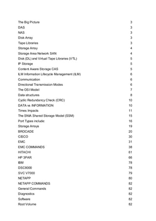
  • 1. The Big Picture 3 DAS 3 NAS 3 Disk Array 3 Tape Libraries 3 Storage Array 4 Storage Area Network SAN 4 Disk (DL) and Virtual Tape Libraries (VTL) 5 IP Storage 5 Content Aware Storage CAS 5 ILM Information Lifecycle Management (ILM) 6 Communication 6 Directional Transmission Modes 6 The OSI Model 7 Data structures 8 Cyclic Redundancy Check (CRC) 10 DATA vs INFORMATION 10 Times Impacts 11 The SNIA Shared Storage Model (SSM) 15 Port Types include: 16 Storage Arrays 19 BROCADE 20 CISCO 30 EMC 31 EMC COMMANDS 38 HITACHI 61 HP 3PAR 66 IBM 78 DSC8000 78 SVC V7000 79 NETAPP 80 NETAPP COMMANDS 82 General Commands 82 Diagnostics 82 Software 82 Root Volume 82
  • 2. Aggregates 82 Volumes 83 Qtree’s 83 Snapshots 83 SnapMirror 83 Cluster 84 Autosupport 84 Hot Spares 84 Disks 84 Luns 85 Fiber FCP 85 iSCSI 85 Cifs 85 NFS 86 HTTP Admin 86 SIS (Deduplication) 86 User Accounts 86 DNS 87 Logging 87 Network 87 OS COMMANDS CHEAT SHEET 112
  • 3. The Big Picture DAS Early mainframe systems used several techniques to manage VD wait and move control away from the CPU. Imagine the motherboard of a personal computer with a special connection to extend the bus outside of the case. Called the channel, this path provided the necessary link between the CPU and its peripheral equipment. lt was expensive. Management of disk requests moved from the CPU to the self-contained [lO controller, now attached to the channel. A similar approach called front-end processor,managed network connectivity. These techniques offloaded the I/O workload from the CPU and more effectively managed the wait for completion of outstanding requests through cache. While mainframe is not a subject area for this course, the concept of a controller is a recurring pattern in the storage infrastructure. Later techniques connected multiple disks to the same bus and transferred control into the disks. This allowed each disk to work independently, in parallel, instead of sequentially. In early personal computing the interface limit was two disks, each clamped on a ribbon cable bus. Enterprise computing often used the Small Computer Systems Interface, known as SCSI (pronounced skuzzy). SCSI gave the appearance of a connection string, although internally it was a bus. a bus with higher attachment limits; each disk has an address describing its logical position on the bus. The physical number of wires in the bus limited the count of available addresses. Address limits are a pattern. Even today, the logical address limits can vary from the standard. NAS As networks emerged and stabilized, it was not enough that we could move data or files on the network; it was inconvenient and had serious limitations. File sharing emerged as a way to make information available to multiple hosts, simultaneously. Storage. connected to a single host, became available to other hosts through the network. The special software served files to clients in response to their requests. The NAS device became a centralized repository for shared documents. At other hosts, known as clients. the remote files appear to be local. The abstraction simply made the files available. Later, this concept gained the title: Network Attached Storage, also known as NAS. Officially, a NAS device is a dedicated file server, optimized for the task of serving files, often, without the ability to be a general-purpose server. File serving and NAS devices are both patterns. File sharing services and specialized NAS devices are very common. lt would be difficult to size the total market because the techniques are in many places. My personal favorite is a sea floor sensor robot that is a client to shared directories in land-based systems where many robots store reports of water current, temperature, waves and other readings for analysis. Robot NAS users. Disk Array The combination ofJBOD with an embedded controller is the earliest form ofa disk array. A disk array is a set of one or more commonly addressable disk subsystems, combined With a body of control software. The control software presents the disks’ storage capacity to one or more hosts as one or more virtual or logical disks, similar to the volume manager software that ran on the hosts. The control software also includes techniques to protect the data from single disk failure and improve performance. Tape Libraries
  • 4. Tape libraries evolved as common enclosures around one or more tape transports. T he name is an illusion to the books on shelves found in a library. They include common power. tape storage and media handling devices. Larger versions include many drives, extensive media storage and complex shared robotics. Unlike the controller in a disk array, the controller in a tape library focuses on media and robot management rather than performance and protection. Most rely on host control software to manage I/O. Protection usually means tape copies. controlled by a host with added integrity checks that are part of the tape transport or the duplication software. Some new forms include disk and tape under the same controller. The term tape array is a more proper description, but less commonly used. Storage Array The phrase Storage Array emerged as a collective term to describe a disk array with enhanced capabilities. Unlike a group of separately managed disk arrays, a storage array provides common management and shared access to a collection of one or more disk arrays, referred to as the aggregated storage elements. In almost every vendor, cache algorithms adapt to use access patterns to reduce I/O wait for read and write requests. Some of the special services include local and remote replication. snap, and secure delete. New services tend to start here and are later move down to disk arrays. The informal array classes include frame, modular and mid-tier. The largest frame arrays include a cabinet of controller electronics and supporting cabinets to hold over a thousand disks. This gives you an internal capacity of over 500 terabytes. Few need that much storage, however the construction of frame arrays offers the best resiliency. As a result, they are at the enterprise core. Mid-tier arrays are more practical through 80 or 90 terabytes, at lower cost; making them the growth area of the industry. Many enterprises surround the core with mid-tier to reduce cost. Three more patterns. Storage Area Network SAN Storage Area Networks (SAN) give us the ability to move data between the computer systems and storage elements. and among the elements without direct physical paths. A SAN is most often a switched communications infrastructure. It provides physical connectivity and a management layer to organize the connections, storage elements and computer systems so that data transfer is both secure and robust. We loosely think of DAS and SAN as moving blocks of data. In contrast. we thing of NAS as moving whole files. Many people believe that the term SAN is a synonym for Fibre Channel technology. Yet, the pure definition suggests that any form of network whose primary purpose is to “provide access to storage elements" is a SAN. In addition. a SAN does not need to be switched; it just needs to be a network. We use the term Fabric to bring focus to the switch interconnections. The fabric exists between any two ports connected to end devices. called nodes. A node can be any device that is not a fabric device. The fabrics’ purpose is to transmit data between nodes. The path is a virtual channel. Therefore, the SAN is the entire environment and the fabric is a subset. Having a switching fabric is a big benefit because it solves many connectivity problems. Giving access to any attached resource, it allows placement of equipment where it makes the most sense, and establishes a consistent connectivity pattern. The typical pattern is point-to-point, from a node to the fabric. The fabric takes care of the rest. Fabrics do have cost. but the benefits outweigh the cost in many scenarios.Convenient access to resources makes the fabric very practical. Consider a remotely managed data center. You can add disks to a server, bypass a failing tape drive and add or replace a server without the physical presence of a single person in the data center; you just need properly connected devices. Fabrics make it possible to consolidate and centralize resources. However, some people take the approach a bit too far. They ignore the network 80/20 rule that 80% of all traffic is local. It is still
  • 5. important to use good judgment when placing physical resources. Storage devices are less forgiving. but are more tolerant of single bit errors than say Web or IP based connections. However, given guaranteed. high-speed network facilities, it becomes possible to link the fabrics. Once the link is in place. you can access remote resources. Perhaps you want to copy a tape from the local tape library to the remote library. meeting a legal or insurance requirement to store backups in a distant location. By using the extended fabric, you will not worry about the tape will falling off the back of a truck. causing the company to be in the headlines for losing personal information. Disk (DL) and Virtual Tape Libraries (VTL) Disk (DL) and Virtual Tape Libraries (VTL) use disk array technology for backup and recovery. VTL is the most popular approach. ln a VTL. the disk array appears to be many tape transports, using disk space to create many virtual tapes. The sizes of the virtual tapes are similar to real tape. Because it uses a common tape metaphor, it is easy to setup and use, in addition, it easy to copy from virtual to real tape. In contrast, the disk library looks like a big disk, and the backup is just a file on disk. In both cases, recovery of independent data from the disk is much faster because it does not have to load or move tape. File access within the backup virtual tape or backup file is just a bunch of pointer and offset arithmetic. However, the time for a lull recovery varies too much to make a performance statement. it may be better, worse, or the same. We can meet disaster recovery requirements by copying the backup blocks in the library to a remote location. In addition, a new technique called data de-duplication reduces total requirements while increasing the number of recovery points. IP Storage IP Storage allows hosts to connect to disk and tape via the TCP/IP protocol. Variants allow Fibre channel extension services. The concept that “any network whose primary purpose stop access storage elements qualifies as a SAN”, is more difficult when we consider IP based storage. lt is Similar to in that its primary fabric is the internet. It is different in that IP Storage moves blocks and NAS move files. NAS is not in the category of SAN. it certainly is not a fabric, and you cannot find a box called a NAS switch. IP Storage, although sharing networking resources with other kinds of traffic, appears to be a fabric, a virtualized fabric within the internet, and for that reason, it loosely qualifies as a SAN. A less pure. view is that IP Storage is hybrid technology at a great price point. Many vendors released IP Storage with embedded aggregation, virtualization and services that work well With inexpensive disk. Some vendors only added IP Storage under duress, because end-users put an ISCSI check box on their RFP`s. However, it offers new fabric options, including connection on IP or Fibre Channel or both with known patterns. Now that people have tried it, they are using it more. IP Storage is an Important technology that will change the face of storage infrastructure. Content Aware Storage CAS Another set of emerging technologies includes Object Storage Device (OSD) and Content Aware Storage (CAS). While different in execution. they both challenge the notion that a computer needs to know where the blocks are stored. When you store data using either technology, these deVices return an object identifier and perform all the tasks of finding blocks without burden to the host operating system. When you want to retrieve data, you provide the identifier. This is a transfer of control from the operating system into the storage. The OSD side is hardware aware, implemented in the storage layer and the CAS side is software aware. implemented in a controller. In CAS and OSD, both can set metadata flags to render a file immutable (i.e., un-erasable) for a unit of time, or set a flag to encrypt the file on disk without using compute cycles for the calculations. These are just two possible functions. OSD is block based. built within IP Storage. CAS is IP network based and may appear as a file based technology. They are useful for meeting regulatory compliance making them of much importance today.
  • 6. ILM Information Lifecycle Management (ILM) ILM Information Lifecycle Management (ILM) is one of the buzzwords of the storage industry today. It is both a concept and an emerging technology. The concept existed for a very long time. Yet, the technology is only emerging. This paradigm causes confusion, but at least it now has a label. On first glance at the big picture, you see all of the technologies we just considered and you realize that many parts were missing. Then look at it again, and awareness comes over you that those parts only exist to meet requirements. Communication Communication, at its most human form, is the process of exchanging ideas and information. We exchange them by the written word, speech and signaling. It is an active process. The process involves the encoding, transmitting, and decoding of messages. Messages are the object of the exchange.There are many means of communicating and many different language systems. Yet speech and language is only a portion of our exchange. Other aspects of communication may enhance or even eclipse the linguistic code. These aspects are paralinguistic, nonlinguistic and metalinguistic. paralinguistic mechanisms signal attitude or emotion and include intonation, stress, rate of delivery, and pause or hesitation. Nonlinguistic clues include gestures, body posture, facial expression, eye contact, head and body movement, and physical distance or proxemics. Metalinguistic cues signal the status of communication based on our intuitions about the acceptability of utterances. In other words, metalinguistic skills enable us to talk about language, analyze it, think about it, separate it from context, and then judge it. The process has three stages, encode, transmit and decode. • Encode: In a digital sense, the encoding process converts binary data into the signals appropriate for transmission across a communications channels. Often, the process encapsulates the message in a frame (the envelope), along with a code to check for errors in the message, on receipt. If privacy is a concern, we may encrypt the message. • Transmit: The transmission channel works within a set of behavioral algorithms, message formats and message semantics used to support communications between the entities across a network. • Decode: On receipt, the decoding process converts the signals received from the signaling of the communications channel to the binary data of the end-point. Expectation It is a reasonable expectation that the delivery of the message will be without alteration, in a predictable time to the intended recipient. In addition, the user expects transparent processing, i.e., they do not need to know how the network does it, just, that the message will arrive. Metadata Not all messages represent content. Some messages contain control information or data about the data. They may be just as important, if not more important than the original message. Directional Transmission Modes In traditional data communications, we say that there are three (3) directional transmission modes: simplex, half-duplex and full duplex. Used in a storage sense, the latter two of these patterns describe the way that we connect our storage to a host. Knowing the difference will help you to know the potential bandwidth between two points.
  • 7. Simplex transmission is in only one direction between sending and receiving nodes. It is similar to a one-way street. Typical examples include broadcast transmission from radio, television or satellite sources. Generally, the receivers are unknown; however, they know the transmission frequency. Half-duplex transmission, also known as “HDX”, is the ability of a transmission facility to transport data in both directions, but not simultaneously on the same link. A half-duplex facility uses some form of Request-to-Send (RTS) and Clear-to-Send (CTS) to manage transmission direction. For example, a half-duplex, 100-megabyte (100 MB) connection has 100 MB of bandwidth.We associate half-duplex with a shared transmit and receive connection. Full-duplex transmission, also known as “FDX” is the ability of a transmission facility to transport data in both directions, simultaneously. A full-duplex facility, also known as the link, typically contains two unidirectional channels, transmitting in opposite directions. Effective bandwidth doubles because the facility can send and receive over the same link. For example, a full-duplex 100-megabyte (100 MB) connection has 200 MB of bandwidth. We associate full duplex with an independent transmit and receive connection. The OSI Model What is OSI? The OSI Reference Model describes the functions and interfaces that enable computers to communicate with each other. There are seven (7) functional layers in the model. Each layer is a group of related functions that provide services to the layer above. while receiving services from the layer below. For any layer there is only a need to know the interface protocol of the adjacent layers and of no others. In current practice cross-layer optimization breaks the boundaries, however the functions remain. Published in 1984 by the International Organization for Standardization (ISO), it remains the primary reference for communication protocol design. Why? Because it is a layered architecture, with ordered functionality and defined interfaces that we combine to meet our purposes. Relevance: Many of the concepts and terms of OSI are common to other forms of networking, including storage networks. The unique nature of storing data requires variance from the model, yet the terms remain Within storage specifications. However, you need to take care as some storage terms have context sensitive use that differs from 081. It is a good place for us to start in the study of storage protocols. The following list outlines the seven layers of the OSl model. Layer 7 The Application Layer Provides networking services to user-defined applications or process and it issues requests on their behalf to the presentation layer. It serves user interface functions for programs like telnet, HTTP and SMTP; however, it is not a human interface. For example, an e-mall program is above this layer. When we write an e-mail and hit send, this sublayer provides the functional elements that takes data from the program and prepares it for placement on a network. Layer 6 The Presentation Layer PRovides formatting services to the application layer. It establishes context between application layer entities while encapsulating Presentation Service Data Unit into Session Protocol Data Units and moving them down the stack. Higher-layer entities may use different syntax and semantics, as long as this layer understands both entities, and the mapping between them. This layer seems confusing on first read. A way to think of the formatting services is like a human translator. The person hears the words and loosely converts words from one language to another Within a context of cultural knowledge. This results in equal meaning, preserving the message. For example, if the source computer sends a JPEG, and the destination computer needs a GIF, this layer would reformat the presentation. In this case, the mapping is loose. It is important to note that there is no rule that translation occurs in the sender or receiver. Other user interface functions that are more rigid include character set conversion, e.g., ASCII to EBCDlC, serializing objects and
  • 8. other data structures into and out of XML, and cryptographic encoding rules to allow end-to—end encryption in this layer. Layer 5 The session layer Manages connections between hosts. If an application on one host needs to talk to an Session application on another, the application layer sets the connection up and ensures resources are available to facilitate the connection. You need all three layers to do the setup. Network people tend to refer to Layers 5-7 collectively as the application layers. Layer 4 The transport layer Is responsible for taking the chunk of data from the application and preparing it for Transport shipment or placement on the network. Prepping data for transport involves chopping the chunk into smaller pieces and adding a header that identifies the sending and receiving applications (otherwise known as port numbers). Each piece of data and associated headers is called a packet. Content switches operate at this level. Layer 3 The network layer Is responsible for adding another header to the front of the packet, which identifies Network the unique source and destination address. The process of routing IP packets occurs at this level. Layer 2 The data link layer Is responsible for adding another header identifying the particular Layer 3 protocol Data Link used and the source and destination hardware addresses (also known as Media Access Control (MACAddresses). At this point, the packet is complete and ready to go onto the network. Ethernet switching and bridging operate at this level.It is important to appreciate that the data link layer includes several functional components that include: • Error Control • Flow Control and • Connection Management Layer 1 The physical layer Is responsible for converting the packet into binary signals to be transmitted over Physical the network. The actual physical network can be copper, fiber, or wireless radio frequency. This layer also provides a method for the receiving computer to validate that the data was not compromised during transmission. The combination of the seven layers is often called a stack. A transmitting workstation traverses the stack from Layer 7 down to Layer l, converting the application data into network signals. The receiving workstation traverses the stack in the opposite direction: from Layer 1 to Layer 7. It converts the received transmission back into a chunk of data for the running application. Each layer of the OSI model uses its own protocol to communicate with its peer layer in the destination device. The OSI model specifies how each layer communicates with the layers above and below it, allowing vendors to focus on specific layers that work with any other vendor’s adjacent layers. Data structures Data structures enable the network to use, store and transmit data efficiently. They evolved to be the most efficient algorithm within the context of the messages they expected to transmit and the network they would traverse. The choice of data structure often begins from the choice of an abstract data structure. Then, they evolve over time as the context and network changes. Our well- designed data structures, allow for performance of critical operations in the process of transmitting data.
  • 9. A message is an object of communication. It is something, which provides information; it can also be this information itself. In this case, the meaning is dependent upon the context in which it is used; the term may apply to both the information and its form. More precisely, in the communication science, a message is information, sent from a source to a receiver. Some common definitions include: • Any thought or idea expressed briefly in a plain or secret language, prepared in a form suitable for transmission by any means of communication • An arbitrary amount of information with a defined or implied beginning and end • Record information, a stream of data expressed in plain or encrypted language (notation) and prepared in a format specified for intended transmission by a telecommunications system Note that the message is not necessarily the payload. The payload or mission bit stream is the data, such as a data field, block, or stream, being processed or transported the part that represents user information and user overhead information. It may include user-requested additional information, such as network management and accounting information. In addition, the payload does not include system overhead information for the processing or transport system. Finally, owing to size, a message may be broken into multiple payloads. Segmentation has several contexts. In the context of a message, we recognize that the size of a message may be larger than the maximum payload size of a packet. In a single network with known maximum packet size, the transport layer protocol can immediately divide, segment or fragment, larger messages into smaller units for transfer cross the network. In the case of internets comprising networks with varying maximum packet sizes, however, either the minimum packet size must be known; otherwise, the end-point will default to the local maximum. If it is not known, then the network layer in each end and intermediate system must perform the necessary segmentation (fragmentation) and reassembly operation. The first alternative will result in some networks in the path being used inefficiently,while the second requires an additional function to be performed by the network layer. Note that we use the term segment in the context of the original message being split into smaller units, while we use the fragment in the context of a packet being remade into smaller packets. The term segmentation is also used in the context of network, to split or isolate a network workload. A packet is the fundamental unit of information carriage in all modem computer networks. The packet is a formatted block of data carried by a computer network. Networks that do not support packets, such as traditional point-to-point telecommunications links (not to be confused with other point-to-point circuits); simply transmit data as a series of bytes, characters, or bits alone. When data is formatted into a packet, the network can transmit longer messages more efficiently and reliably. The term datagram is sometimes also used, and in some contexts its meaning is subtly different from packet. A packet consists of two kinds of data, protocol control information (PCI) and user data, also known as the payload. PCI carries information about the user data, such as source and destination address, error detection codes, like checksums, and sequencing information. Typically, PCI is found in packet headers and trailers, with payload placed in between. Packet vs Datagram In general, the term packet applies to any message, formatted as a packet, while the term, datagram is generally reserved for the packets of an unreliable service. A reliable service is one where the user is notified if delivery fails. An unreliable service is one where the user is gm notified if delivery fails. For example, IP provides an unreliable service. TCP uses IP to prove a reliable service, whereas UDP uses IP to provide an unreliable service. All these protocols use packets, but UDP packets are generally called datagrams. When a network does not guarantee packet delivery, then it becomes the host’s responsibility to provide: reliability by detecting and retransmitting lost packets. Our experience during the early days of the internet indicated that the network itself could not reliably detect all packet delivery failures. As a result, the responsibility for error detection was pushed on the sending host, i.e. was
  • 10. the message received, if not, retransmit. This led to the “end-to-end” principle, which is one of the Internet`s fundamental design assumptions. Whenever possible, communications protocol operations should be defined to occur at the end- points of a communications system, or as close as possible to the resource being controlled. Cyclic Redundancy Check (CRC) To assure that the message sent is the message received, at a minimum, packet based network protocols implement a cyclic redundancy check (CRC). The term CRC is often used to denote either the function or the function's output. A CRC can be used in the same way as a checksum to detect accidental alteration of data during transmission or storage. CRCs are popular because they are simple to implement in binary hardware, are easy to analyze mathematically, and are particularly good at detecting common errors caused by noise in transmission channels. A CRC is an error-detecting code whose computation resembles a long division computation in which the quotient is discarded and the remainder becomes the result, with the important distinction that the arithmetic used is the carry-less arithmetic of a finite field. The length of the remainder is always less than the length of the divisor, which therefore determines how long the result can be. The definition of a particular CRC specifies the divisor to be used, among other things. Although CRCs can be constructed using any finite field, all commonly used CRCs employ a finite field, the field of two elements, usually called 0 and l, comfortably matching computer architecture. We will only discuss binary CRCs, but the principles are more general. CRCs are not, by themselves, suitable for protecting against intentional alteration of data (for example, in authentication applications for data security), because their convenient mathematical properties make it easy to compute the CRC adjustment required to match any given change to the data.It is important to understand that while useful for error detection, CRCs cannot be safely relied upon to verify data integrity fully in the face of intelligent (rather than random) changes. Novices sometimes assume that a CRC can guarantee verify data integrity; their reasoning suggests that: if a message and its CRC are encrypted then transmitted over an insecure channel on receipt, decrypt check that decrypted CRC matches the decrypted message then the message cannot have been altered in transit SAN protocols use CRC mechanisms. However, SANS go further, using 10-bit bytes with embedded parity in addition to CRC. This technique allows Fibre Channel to recover from single bit errors using the CRC to validate the correction. In a typical Ethernet based network, a single-bit error would require retransmission“. Under increasing load, such a network would experience more retransmission, which in turn would further increase load, at some point creating an avalanche. The SAN protocol authors recognized the impact of retransmissions and opted for an approach that made the protocols’ performance more predictable under load. The disk drive industry also uses variants of these techniques. DATA vs INFORMATION There is a big difference between the terms data and information. Many people use them incorrectly, because they believe that they are interchangeable. Care in using these terms will help you to consistently describe storage technologies. Data is a grouping of bits and bytes that may contain an individual fact or multiple facts, or a value, or a set of values, but they are not significant in and of themselves because they are without context. Information has context. Context converts data into information. Without context, the data is useless to the owner. When storing data on paper forms, the forms have headings to give meaning
  • 11. to the data. In the past, we would file the forms in folders and drawers and cabinets, each with labels. Today, we preserve these approaches in windowing and database metaphors using data structures, directories and file names. Times Impacts We are always waiting for a response from the system, even in a system that is close to perfection. All architectures are a collection of time impacts. Understanding their sources and limits is key part of all storage and systems work. The measures of delay, latency, and response time are often overlooked; however, they are very important because the cost of improving them is a function of the value we place on performance, from either the end-user or the machine’s perspective. Latency is the delay induced by the physical structure of a device or process. ln the case of a medium such as fiber or wire, the limit is the speed of light. We cannot make light faster; therefore, the latency is a function of length and is predictable. Unlike latency, delay varies according to the time spent in queue. An overloaded device at any point, end-to-end can induce delay, and that delay may be unpredictable. Response time is one of the most important storage performance metrics, denoting the time it takes to finish a given storage operation. The operation could be defined as any of these storage operations: read, write, open, close, search, etc. The response time is measured from the initiation of the operation(request) to the completion of the operation (reply.) End-to~end measurement is most important, and includes all times of all components. Often, response time is graphed against throughput in IOPS. Response time is a range of time (measured in milliseconds) where each response to the corresponding request must fall. The appropriate range is a defined metric between lT and the user of the system. It is specified in a Service Level Agreement (SLA) typically measured from the perspective of the end-user. A failure to meet the SLA occurs if a specified percentage of requests fall outside of the stated range over a specified time. Remediation may require an adjustment in workload or the infrastructure. Utilization is the fraction of time that a resource (channel or device) is busy. It is expressed as a fraction of the resources total capacity. Utilization has a direct impact on response time. For example: an increase in utilization results in an increase in response time, approaching infinity as utilization approaches 100% and a decrease in utilization results in a decrease in response time, approaching the standard, no load, service time. This is true in a system based on random arrivals. Value Perhaps you want to play a game that requires you to reboot your workstation. If there was something that you could do to make the workstation reboot more quickly, then you could get back into the game more quickly. The personal effort and/or components required to reduce reboot time have cost, however, that cost may be offset by the value you place on gaining more game time. In a similar way, changes in these time impacts have value when a business owner can see a financial benefit by using better or additional components and/or architectural changes. Combining these thoughts, latency is often internal to components, a function of distance or architectural design limit, and is difficult to change unless we use higher quality components, reduce distance or change the architecture. However, we can reduce delay by providing more queues and simultaneously decrease response time by lowering utilization. As you can see, managing time, i.e., performance is both art and science, limited by value. Bandwidth is the total amount of data transferred through a system or medium over a unit of time, also known as data transmission rate. Bandwidth is often described using two different levels:
  • 12. Raw bandwidth or line-speed is the specified transmission rate of a component. A transmission line or bus will have a physical signal rate that determines the maximum possible data rate. The user guarantee is not to observe anything faster than this specified rate. Sustained bandwidth is the data rate after accounting for all the overheads that might be needed for the transmission operations. The sustained bandwidth will always be less than the raw band- width if the transmission medium has contention or if parts of the transmission are not considered usable data. Sustained bandwidth is a better representation of the performance a user observes when using the component. Tradition requires use of upper case “B” for bytes and lower case “b” for bits. The bit rate is the number of bits that are moved or processed per unit of time. It is inclusive of the useful data as well as the protocol overhead. In contrast, the net bit rate, useful bit rate or information rate excludes the physical layer protocol overhead, but generally, not the network layer protocol overhead. Throughput is an average of the amount of work performed by a component or system over a unit of time. Throughput is generally expressed in operations per second, transactions per second or bytes (of useful data) per second. Although throughput and bandwidth are sometimes used interchangeably, there is a fundamental difference. The difference stems from the fact that operations reported in the throughput can have different data sizes. This affects the bandwidth directly; therefore, we need to understand the impact of block or transaction size on actual throughput. We know in the case of hard drives, low block size yields higher lOPS but exponentially lower throughput. ln a network, throughput often excludes data link layer protocol overhead and sometimes network layer protocol overhead. It is not an instantaneous measure, but rather a long-term average measured at a reference point below the network layer and above the physical layer. The maximum theoretical throughput is the maximum possible quantity of data that can be transmitted under optimal circumstances. lt is similar to, but usually lower than channel capacity. Channel capacity is the upper limit of the amount of information that can be transmitted over a communications channel, reliably. IOPS l/O´s per second are a measure of performance for storage devices. Unlike bandwidth, it represents the number of exchanges with a device at a specific block size. Bandwidth is approximately equal to request size * lOPS. If a device makes a claim to be capable of a maximum number of lOPS, the claim should include the block size, random or sequential requests and cache hit ratio; if unstated assume the lowest block size at 100% cache hit-ratio. Availability is the proportion of time that a Customer is able to access a particular service. The measure of availability is from the Customer’s point of view. Availability depends on: • Reliability of components • Resilience to failure • Quality of maintenance and support • Quality of operating procedures Reliability of a service is determined by the amount of freedom from operational failure. Reliability can further be defined as the ability of components to perform a required function under stated conditions for a stated period. Measurements of reliability include: • Mean Time Between Failures (MTBF) • Mean Time Between System Incidents (MTBSl) • Number of breaks per unit time (period) • Resilience built into the service • Preventative maintenance applied (assumed, but measured)
  • 13. Serviceabilityis the ability of external suppliers to meet the contractual conditions regarding reliability, maintainability and maintenance support of components. Security Availability Management is closely related to security as the Availability of all IT Service components also includes data. The relevance of Availability in Security, as previously mentioned, is shown in the CIA rule: • Confidentiality • Integrity • Availability JBOD has the un-enviable problem of depending on the host for the management of data protection services. This takes processor cycles away from its regular work, and limits the overall protection to the uptime of the system. RAID based systems manage the data protection within their system and promise to manage faults, within limits. Often, using battery backups, they can guarantee that data will not be lost (except if someone pushes the big red emergency shutoff of the back). MTBF is a relative number, relative to time. As a drive ages, it’s Mean Time Between Failure accelerates from I loss per 1,000 in I I4 years to 44 failures (+|- 11) over a five-year span. Probability of failure is greatest for mechanical components, like a disk drive. Therefore. PFO' tecting data on disk is the first line of defense against data loss caused by equipment failure (people cause failures more than equipment). The channel poses the next greatest risk to availability. If data protection services, such as mirroring are used. and both drives share the same physical channel, the channel becomes a single point of failure. We increase availability by using at least two channels when accessing one or more storage devices. If the server fails. we increase availability, or reduce risk to availability by using one or more additional servers, with access to the same data. The SAN is particularly useful in making data available to multiple hosts. Replication and copy services, local and remote, enable higher availability Storage arrays. also known as striped or mirrored drive arrays provide data protection services, on a large scale. Most arrays are a blend of protection services. Parity checking verifies data transmission. RAID technology provides capacity and management benefits, while improving performance (due to distributed disk activity,) reliability and availability (if one disk fails. others keep working). Disk striping with parity is the method of fault tolerance that provides the fastest read/write performance. There are six levels of RAID surrounding the commonly known, RAID 0. RAID 0: Striping RAID 1: Mirroring RAID 2: Striping with ECC RAID 3: Synchronous Access. Dedicated Parity RAID 4: Independent Access, Dedicated Parity RAID 5: Independent Access, Distributed Parity RAID 6: Independent Access. Distributed Dual Parity
  • 14. Continuous Data Protection (CDP). captures changes to data, the delta, and storage them to a separate location. The captures are time based and allow a change of view to the way the data looked at a specific point in time. It is not a substitute for a backup; however, it is useful in the backup process. Content Addressable Storage (CAS) stores content as ‘objects’ which consist of data and annotated metadata. lt generates a globally unique name (address) for each object that is independent of the current computing environment, organization, location or technology; therefore objects can be moved. transparently (i. e., without knowledge or intervention of the owner Data De-duplication is a method of reducing storage needs by eliminating redundant data, i.e., discovering duplicate blocks and internally replacing them with pointers to a shared block. Thin Provisioning is a method of optimizing the efficiency with which the available space is utilized by recognizing that all blocks begin as null blocks, and that real storage only need be provisioned when a block is non-null. This technique gives the appearance to the host operating system of full provisioning. Thin provisioning can increase data fragmentation, impacting performance. Replication services, local and remote, in addition to snap and CDP services, aid in backup and recovery. They work by managing the relationship of blocks in the original data to sets of blocks storage in another part of the storage subsystem. By copying the blocks, i.e., creating an image, the image becomes useful for other purposes. By maintaining a list of changes to the blocks in the original a view to a point-in-time is created. Using the metadata enables recovery, via changed blocks, or continuing changes to be recorded. Remote replication introduces special dependencies into the infrastructure, the relationship of timed response from the storage subsystem to the host, based on the type of replication selected. These types: Synchronous, Semi-synchronous, Asynchronous and Adaptive each respectively decrease the availability index of the data; however, decrease the cost of providing the service, by reducing the bandwidth requirements.
  • 15. Storage virtualization, originally provided by the host operating system, then by the storage array. becomes available as an appliance. lt is the act of integrating one or more back-end services or functions with additional front-end functionality for the purpose of providing useful abstractions. Essentially allowing you to create from any networked storage, new devices, and apply other services to those devices. Volume management, most often thought of as a host tool, provides an ability to create groups of disks as a pool of logical extents (or blocks) from which logical disks are created in the size that you want. File systems reside on disks, physical or logical, and are the essential component of all processing in the infrastructure. They provide the access structures (directory/file and permissions management) and integrate with a common system call interface. Security services, including device and link encryption, and port authentication are essential parts of today’s storage infrastructure. Administrators need to apply the same duty of care to storage infrastructure as they do to any other infrastructure. The SNIA Shared Storage Model (SSM) is a model, not a product, intended to move the industry toward storage services rather than the current state as a subsystem or a peripheral. A storage service must be shared, stable and take on an independent lifecycle. This is consistent with changes to other parts of the IT infrastructure. It yields increases m reliability, scalability, manageability and interoperability while reducing the total cost of ownership and improving financial performance and efficiency. The primary value of the model is providing a common vocabulary to assist in creating common comparisons between common solutions so that clients can have better structure in their choices and vendors can better explain their differences. Before the model, language was “ad hoc” and focus was box or brand centric. SSM has three main components, file/record layer, block layer and services subsystem. The file/record layer packs small things such as files (byte vectors) and database tuples (records) into larger entities such as block—level volumes and storage device logical units. The block layer provides low-level storage to higher layer, typically with an access interface that supports one or more linear vectors of fixed-size blocks. These logical address spaces are called logical units (LUs) in SCSl. A secondary responsibility is simple form naming, such as the Logical Unit Name or LUN. Within this layer we find block aggregation. Block aggregation manages space, striping and redundancy (through RAID). It can be done in the host, network or storage array. lt imports block vectors from the devices below and exports one or block-vectors as aggregated or virtualized volumes to the higher level users. ln addition, it can make multiple associations, enabling specialized copy, snap, and other services. There are eight (8) possible paths from the application layer to the physical storage de- vices. Caching can occur in any layer, in any device. • The existence of access paths does not imply permission to use. Access control encapsulates permissions. • The third main component is the service subsystem. It covers the storage domain and crosses the block and record layers.
  • 16. • Data is not storage. The recursion is: information (the meaning of data, i. e., data + context), data (the bytes to be stored), and containers (the place where the bytes are stored. Direct Attached Block Storage includes one, and only one (active) host on each storage interconnect. It does not use switches or hubs, although extenders (repeaters) are allowed). In addition it uses the block interface protocol for all operations over the Interconnect. SAN-Attached Block Storage enables multiple hosts and devices to attach to a shared storage interconnection. lt uses a block interface protocol over the interconnect. Each host is configured with a consistent allocation of the shared device resource. Block storage aggregation in a storage network, aka, SAN Appliance has multiple hosts and devices attached to a shared storage interconnect, employs a block interface protocol over the interconnect and by providing block-aggregation functions in a dedicated “appliance” that is on the data-data path for each operation. Storage network-attached block storage with metadata server, a. k.a., asymmetric block service, enable multiple hosts and devices attached to a share storage interconnect, to communicate directly with the storage devices while employing a metadata service to provide layout information (“block metadata”) to the hosts on the current layout of block data on those storage devices. The interconnect uses a block interface protocol. Multi-site block storage is characterized by the use of peer-to-peer protocols between like components of two or more systems at different sites to maintain data replicas at each site. A File Server is a self contained, single package that contains storage devices and a file/record subsystem controller. It employs client-server file/record protocol to access the data and uses a network that is typically not specialized for or dedicated to storage traffic, typically a LAN. File Server Controller, “NAS head” decouples storage devices from the file/record subsystem controller that provides access to them. lt employs a client-server file/record protocol to access the file/record subsystem from the client hosts, and uses a network that is typically not specialized for, or dedicated to storage traffic. NAS/file server metadata manager, a. k.a., “asymmetric file service” allows multiple hosts and devices to attach to a shared storage interconnect that employs a block interface protocol. It uses a separate file system metadata (data about the data) server using an extended client-server file/ record protocol, to obtain layout information for the files they wish to access, and then enables direct access across the share storage interconnect, using a block interface protocol. Object-based Storage Devices (OSD), a.k.a., CMU NASD (Carnegie Mellon University Network Attached Secure Disks, is a storage device where the device take4s on the data-layout responsibilities, exporting a large number of “byte vectors” (objects) rather than a small number of logical units; each such object is typically used to hold the contents of a single file. lt also employs a separate metadata server to provide object access and authentication information to the hosts, and optionally, the storage devices using an extended client-server file/object interface. FIBER CHANNEL There are several types ofFibre Channel ports. Port Types include: B_Port Identifier for bridge port: a pen within a bridge device used to extend a Fibre Channel inter-switch link. The B_Port connects only to an FL_Port on a Fibre Channel Switch. E_Port
  • 17. Identifier for expansion port: connects a Fibre Channel switch to another Fibre Channel switch or bridging device via an inter-switch link E_Ports are used to link Fibre channel switches to form a multi-switch fabric. EX_Port Identifier for non-merging expansion port: a type of E_Pott used to connect a multi protocol router to an edge fabric. An EX_Port follows standard FL_Port protocol and supports FC_NAT but does not allow fabric merge across EX_Ports. This port is vendor specific. F_Port Identifier for fabric port: port on a switch connected to a node. lt is the "Fabric" port within a Fibre Channel fabric switch that provides a point-to-point link attachment to a single N_Port. F Ports are intermediate ports in virtual point-to-point links between end ports, for example N_Port to F Port to F_Port to N_Port using a single Fibre Channel fabric switch. FL_Port Identifier for fabric loop port: A "Fabric Loop" port within a Fibre Channel fabric switch is capable of Fibre Channel Arbitrated Loop operations and is connected to one or more NL_Ports via a Fibre Channel Arbitrated Loop. An FL_Port becomes a shared entry point for public NL_Port devices to a Fibre Channel fabric. FL_Ports are intermediate ports in virtual point-to~point links between end ports that do not reside on the same loop, for example NLgPort to FL_Port to F Port to N Port through a single Fibre Channel fabric switch. G_Port Identifier for generic port: A "Generic" switch Port that can operate as either an E_Port. EX_Port or an F_Port. A G_Port can determine operating mode at switch port initialization. F_Port when an N_Port attachment is determined, S_Port when an E_Port attachment is determined. L_Port Identifier for loop port: A "Loop" port is capable of performing arbitrated loop functions and protocols. NL_Ports and FL_Ports are examples of loop-capable ports. N_Port Identifier for node port: A "Node" port connects via a point-to-point link to either a single N_Port or a single F_Port.N_Ports handle creation, detection. and flow of message units to and from the connected systems. N_Ports are end ports in virtual point-to-point links through a fabric, for example N_Port to F_Port to F_Port to N_Port using a single Fibre Channel fabric switch. NL_Port Identifier for node loop port: A "Node Loop" port is capable of arbitrated loop functions and PTOIO' cols. An NL_Port connects via an arbitrated loop to other NL_Port and at most a single FL_Port. NL_Ports handle creation, detection, and flow of message units to and from the connected systems. NL_Ports are end ports in virtual point—to-point links through a fabric, for example NL_Port to F_Port to F_Port to N_Port using a single Fibre Channel fabric switch. In the absence of a fabric switch F L_Port, NL_Ports can communicate with other NL_Ports in virtual point-to-point links through a FC-AL open loop circuit often through FC-AL (Arbitrated Loop) hub or loop switch devices. S_Port Identifier for service port: A logical port inside a switch addressable by external N_Ports for service functions. An S_Port may be an implicit switch port or a separate entity such as a name server connected to and controlled by the switch, S_Ports have well known port names to facilitate early discovery by N_Ports. U_Port Identifier for universal port; a port that can operate as a G_Port, E_Port, F_Port or FL_Port. Most
  • 18. switches and related fabric devices contain Universal Ports to allow any device to connect to any port, with selection of the actual port type being automatic. ' VN_Port Identifier for virtual network port: a virtual node port, used when an HBA is addressed as multiple virtual HBAs in a virtual machine environment. The VN_Port acts as an independent entity, although the physical device may support one or more active VN_Ports. Similar to the OSI model used for IP, Fibre Channel standards define a layered communication stack FC-0 defines the physical layer of the model. It defines standards for connectivity and transmission methods. These standards currently define a physical layer data rate 1000 MBps or 10Gbps. • FC-1 defines the encoding layer. It uses 8b/lOb encoding which means for every 10 bits transmitted: 8 bits of actual data are received. • FC-2 defines the construction of the basic data frame, methods of frame sequencing and flow control. • FC-3 defines common services used in a switch. • FC-4 is where all the upper level protocols or ULP get mapped. Commonly used protocols are Serial SCSI-3 and IP. SCSl-3 over Fibre Channel is also commonly referred to as the “Fibre Channel Protocol” or FCP.
  • 19. Fibre Channel Port Types: Fibre Channel standards use the term node to describe any device connected to one or more other devices over Fibre Channel. Each node has at least one port that connects to other ports on other nodes. FC-PC-2 has standardized a shorthand for identifying physical interfaces. the nomenclature for technology options is listed below: EX 400-SM-LC-L SPEED MEDIA TRANSMITTER DISTANCE 1200=1.200 MB/sec SM single mode LC longwave laser cost reduced (1.300 nm) V very long distance (2 m to > 50km) 800=800 MB/sec M5 multimode SO micron LL longwave laser (1,300 nm . 1,550 nm) L long distance (2 m to 10 km} 400=400 MB/sec M6 multimode 62.5 micron SN shortwave laser (780 nm 850 nm) l intermediate distance (0.5 m to 2 km) 200=200 MB/sec SE unbalanced copper EL electrical S short distance (< 100 m) 100=100 MB/sec DF balanced copper Storage Arrays The storage arrays are reliable high-performance Integrated Cached Disk Array designed for online data storage. The lCDA relies on components assembled in a proprietary architecture run by micro-code to ensure optimum performance, availability, scalability and connectivity. In Array, the channel directors and disk directors share cache. Hitachi uses cache in large, dedicated chunks, but path management is switched; the switching backplane prevents the
  • 20. traditional pitfalls of bus arbitration. The crossbar switch architecture establishes dedicated paths between front end (CHIP) and back end(ACP) devices. There are four parameters that HDS uses to support its performance points: • IO queue time • Seek Time • Latency • Transfer time IBM built from off the shelf components, which reduces the manufacturing cost. These components include two RS6000 processors with SSA drive controllers and arrays. Caching is contained in the modified AIX environment, essentially UNIX-like cache, along with control of the Shark. Most arrays support RAID-5, -l/0, -I, -3, -0 Logical Units (LUNs) are bound to RAID groups and then presented to hosts Maximum 32 LUNs/group Maximum of 224 LUNs/array Hot spares are disks that are not available for individual use but stored for use in case of failure. Cache is allocated in pages and can be 2-, 4-, 8-, IG KB in size Write cache contains a bitmap that indicates status of the page Each cache page can be considered “dirty” or “invalid” Each SP bitmap is mirrored to its peer SP Cache is flushed via three methods: idle flushing, watermark flushing or forced flushing Prefetch can be variable or constant. Several parameters define variable prefetch (Prefetch Multiple, Segment Multiple and Maximum Prefetch) and constant prefetch(Prefetch Size and Segment Size) Write-aside caching allows data to be written directly to disk by-passing the write cache Write cache is safeguarded by vaulting, Persistent Storage Manager (PSM) and sniffer components RAID group/LUN expansion methodology enables dynamic storage expansion, This feature is available only with RAID-5, RAID4/0 and RAID-0 groups with less than 16 drives. RAID group/LUN expansion is not available in a RAID 1 or RAID 3 configuration. BROCADE
  • 21. Zoning Commands alicreate “Name”, “domain,port#” Used to create an alias alicreate “Name”,”portname1; portname2″ To create multiple ports under a single alias alidelete “Name” To delete an alias aliadd “Name”, “domain,port#” To add additional ports to an alias aliremove “Name”, “domain,port#” To remove a port from the alias alishow “AliName” To show the alias configuration on the switch zonecreate “Zone Name”, “alias1; alias2″ To create zones based on alias zonedelete “ZoneName” To delete a zone zoneadd “ZoneName”, “alias name” To add additional alias into the zone zoneremove “ZoneName”, “alias name” To remove an alias from the zone zoneshow “zoneName” To show the zone configuration information cfgcreate “Configname”, “Zone1; Zone2″ To create configurations by adding in zones cfgdelete “ConfigName” To delete a configuration cfgadd “ConfigName”, “Zone3″ To add additional zones in the configuration cfgremove “ConfigName”, “Zone3″ To remove a zone from the configuration cfgshow “ConfigName” To show the details of that configuration cfgenable “ConfigName” To enable a configuration on the switch cfgsave To have the effective configuration to be written into the flash memory
  • 22. Show Commands psshow Displays the status of the power supply fansshow Displays the status of the fans tempshow Displays the status of the temperature readings sensorshow Displays the status of the sensor readings nsshow Displays information in the name server nsshow -t Displays information in the name server nsshow -r Displays the information in the name server along with the state change registration details nscamshow Displays detailed information of all the devices connected to all the switches in the fabric (Remote Name Servers) nsallshow Displays the 24 bit address of all devices that are in the fabric licenseshow Displays all the licenses that have been added in the switch date Displays the current date set on the switch bannershow Displays the banner that will appear when logging in using the CLI or web tools httpcfgshow Displays the JAVA version the switch expects at the management console switchname Displays the name of the switch fabricshow Displays information of all the switches in the fabric userconfig –show -a Displays the account information like role , description , password exp date , locked status switchstatusshow Displays the overall status of the switch switchstatuspolicy show Displays policy set for the switch regarding Marginal(Yellow) or Down(Red) error status portshow To show the port status portcfgshow Displays the speed set for all ports on all slots and other detailed port information configshow fabric.ops Displays the parameters of the switch. Ensure all switches in a fabric have the same parameters in order to communicate configshow fabric.ops.pidFor mat Displays the PID set for a switch Core , Native or Extended edge
  • 23. switchuptime OR uptime Displays the uptime for the switch firmwareshow Displays the firmware on the switch version Displays the current firmware version on the switch hashow Displays the status of local and remote CP’s. High availability , heartbeat and synchronization Port Settings portcfgshow Displays the port settings portcfg rscnsupr [slot/port] –enable A registered state change registration is suppressed when a state change occurs on the port portcfg rscnsupr [slot/port] –disable A registered state change registration is sent when a state change occurs on the port portname To assign a name for a port portdisable To disable a port or slot portenable To enable a port or slot portcfgpersistentdisa ble To disable a port , status would not change even after rebooting the switch portcfgpersistentena ble To enable a port , status would not change even after rebooting the switch portshow To show the port status portcfgspeed , To set speed for a port#te – 0:auto negotiated 1,2,4 Gbit/sec , 1 : 1Gbit/sec , 2 : 2 Gbit/sec , 4 : 4Gbit/sec switchcfgspeed To set speed for all the ports on the switch Note – 0:auto negotiated 1,2,4 Gbit/sec , 1 : 1Gbit/sec , 2 : 2 Gbit/sec , 4 : 4Gbit/sec portcfgshow Displays the speed set for all ports on all slots and other detailed port information portcfgdefault To set the port settings to default portcfglongdistance To set the long distance mode . Default is L0(Normal), as per distance will display LE <=10 kms , L0.5 <=25kms , L1 <=50 kms, L2<=100kms , LD=auto , LS = Static portcfgeport Used to disable a port from being a E port
  • 24. Time and Date Settings date Displays the current date set on the switch tsclockserver 10.10.1.1 Instruction for the principal switch to synchronize time with the NTP server (specify the ip address of the NTP server) tsclockserver LOCL Instruction to stop NTP server synchronization (Local time of the switch) date mmddhhmmyy To set the time of the switch when the NTP server synchronization is cancelled tstimezone -5 To set the time zone for individual switches License Commands licenseshow Displays all the licenses that are added in the switch licenseadd To add a new license to the switch licenseremove To remove a license from the switch licenseidshow Based on Switch WWN Banner Commands bannershow Displays the banner that will appear when logging in using the CLI or web tools bannerset To set the banner which will appear when logging in using the CLI or web tools bannerset “” To remove the bannerset (two quotes) Password commands passwd To change the password for that particular login passwdcfg –set - lowercase 3 uppercase 1 -digits 2 -punctuation 2 - minlength 10 -history 3 To set the password rules passwdcfg –set - minpasswordage 1 To set the minimum password age in Days
  • 25. passwdcfg –set - maxpasswordage 30 To set the maximum password age in Days passwdcfg –set -warning 23 To set a warning for the expiration Days remaining passwdcfg –set - lockoutthreshold 5 To set the account lockout thresh hold passwdcfg –set - lockoutduration 30 To set the account lockout duration in Minutes passwdcfg –setdefault To restore the password policy to Factory settings (min length – 8, history -1 , lockoutduration – 30) SNMP Commands snmpconfig snmpconfig for 5.0 above fos agtcfgset snmp config for fos below 5.0 snmpmibcapset for choosing the MIB’s for the snmp settings User Configuration userconfig –show -a / userconfig –show Displays all the account information like role , description , password expiration date , locked status userconfig –add john -r admin -d “John Doe” To add a new account -r = role , -d = description userconfig –show john Displays all the information for the account john userconfig –change - e no To Disable an account , usually default a/cs like admin and user . But ensure before disabling the admin a/c there is another a/c with admin rights userconfig –change - e yes To Enable an account
  • 26. Firmware commands configupload Saves the switch config as an ASCII text file to an FTP server configdownload To restore a switch configuration from ASCII text file Note – Need to disable the switch before downloading the config file configure => cfgload attributes : [y] => Ensure secure config upload / download : [y] Fabric OS v 4.4 & above provides Secure File Copy Protocol (SCP) during upload or download of configurations firmwaredownload To download the firmware to be installed on the switch firmwareshow To be run after installing the firmware on the switch version Displays the current firmware version on the switch fastboot Needs to be run after installing the firmware. This does not include the post. reboot Needs to be run after installing the firmware. This includes the post. Miscellaneous commands killtelnet To kill a particular session which is using telnet configure To configure a switch quietmode To switch off the quiet mode quietmode 1 To suppress messages to the console switchname Displays the switch name switchname “EXAMPLE” To assign a switch name bannerset To set the banner which will appear when logging in using the CLI or web tools timeout Displays the timeout time set for Telnet session on the switch timeout 10 To set a specific timeout time for the Telnet session switchuptime or uptime Displays the uptime for the switch
  • 27. switchcfgspeed To set speed for all the ports on the switch Note – 0:auto negotiated 1,2,4 Gbit/sec , 1 : 1Gbit/sec , 2 : 2 Gbit/sec , 4 : 4Gbit/sec fastboot To reboot the switch without post reboot To reboot the switch with the post switchstatusshow Displays the overall status of the switch switchstatuspolicyshow Displays policy set for the switch regarding Marginal(Yellow) or Down(Red) error status switchstatuspolicyset To change the policy set for the switch regarding Marginal(Yellow) or Down(Red) error status Show Commands show clock To display the system date and time and verify the time zone configuration, use the show clock command. show environment To display all environment-related switch information (status of chassis clock,fan modules, power supply modules etc) show fcalias To display the member name information in a Fibre Channel alias (fcalias) show interface brief shows the status of the ports on the switch. show interface counters port errors and details of transmission. show interface counters brief port transmission details in brief. show interface transceiver shows details of the sfps used on the ports of the switch.
  • 28. show running-config show the details of the switch, ports, firmware, etc. show interface mgmt0 To display the details of the management console. show vsan x To display details of a VSAN. show module To display details of the switching module. show interface fcx/x capabilities To details of the matrix support for that port. show port-resources module x To check port resources like bb credits, rate mode, bandwidth for ports on a 24/48 bit module. show interface trunk vsan x-x To checkper vsan information on trunk ports. show vsan membership interface fcx/x – x To check the vsan membership on port level for an interface. show vsan x membership To check the ports that are part of a vsan. show version To display the version of system software that is currently running on the switch, use the show version command. show vsan To display information about configured VSAN. show vsan usage To check the vsans created and available vsan ids to be created. show wwn To display the status of the WWN configuration. show zone To display zone information. show zoneset To display the configured zone sets. show zoneset active vsan x To display the active zoneset for a particular vsan. show flogi To list all the FLOGI sessions through all interfaces across all VSANs. show hardware To display switch hardware inventory details. show port-channel Use the show port-channel command to view information about existing PortChannel configurations. show running-config To display the running configuration file. show startup-config To display the startup configuration file. show switchname To display the switch network name, use the show switchname command. show tech-support To display information useful to technical support when reporting a problem. show user-account To display configured information about user accounts. show fc-tunnel To display configured Fibre Channel tunnel information. Configuration Commands config t interface fcx/x
  • 29. shutdown / no shutdown This CLI sequence will disable/enable a port on the switch and saves the configurationcopy running-config startup-config config t interface fcx/x This command sequence put a decription for a switch port(here putting description as emcsaninfo) and saves the configuration switchport description emcsaninfo copy running-config startup-config config tinterface fcx/x This will Assign a bbcredits to a switch port and saves the configuration switchport fcrxbbcredit xx/default copy running-config startup-config” config tinterface mgmt0 This will Set ip address for the management interface,set default gateway and save the configurationipaddress xx.xx.xx.xx 255.255.255.255 no shutdown ip default-gateway 1.1.2.3 copy running-config startup-config” config t vsan database to delete a Vsan , cannot delete default vsan no vsan XX config tinterface vsan xx This step will disable or enable a vsan XX shutdown / no shutdown config tinterface fcx/x This will used to set port speed switchport speed 1000/2000/4000/auto/auto max xxxx config tinterface fc x/x This will used for configuring rate mode of a switch port switchport rate-mode dedicated/shared config tinterface fc x/x Steps to add a port to a port channel channel-group x/auto config tinterface fc x/x Steps to manually set the port type on a switch switchport mode e/f/fl/n config t trunk protocol enable Steps to enable trunk protocol on a swith (default) config tinterface fc x/x Steps to enable/disable trunk on a port level switchport trunk mode on/off/auto config t interface fc x/x Steps to configure an allowed list of vsans to communicate through that port (TE switchport trunk allowed vsan x-x/x
  • 30. switchport trunk allowed vsan add x PORT) and allows to add a specific vsan to the allowed list of vsans config tfcdomain restart vsan x Steps to forcefully reconfigure without affecting traffic and force vsan to configure with data traffic affectedfcdomain restart disruptive vsan x config tvsan database Steps to create a new vsan (default) vsan x config tvsan database Steps to delete a vsan no vsan x config tvsan database Steps to create a vsan ,then assign a name. Steps to suspend a vsan and unsuspend itvsan x vsan x name abc vsan x suspend no vsan x suspend end config tvsan database Steps to create a vsan and add a port on interface into a vsan vsan x vsan x interface fcx/x config t vsan database Steps to remove a port on an interface from a vsan vsan x no vsan x interface fcx/x config t vsan database Steps to remove a port on an interface from a vsan vsan x no vsan x interface fcx/x CISCO
  • 31. EMC Front End Director Ports (SA-16b:1) Front End Director (SA-16b) Cache Back End Director (DA-02b) Back End Director Ports (DA-02b:c)
  • 32. Disk Devices Front End Director A channel director (front end director) is a card that connects a host to the symmetrix, each card can have up to four ports. Cache Symmetrix cache memory buffers I/O transfers between the director channels and the storage devices. The cache is divided up into regions to eliminate contention. Back End Director A disk director (back end director) transfers data from disk to cache. Each back-end director can have upto four interfaces (C,D,E and F). Each back-end director interface can handle seven SCSI ids (0-6) Disk Devices The disk devices that are attached to the back-end directors could be either SCSI or FC-AL. Interconnect The direct matrix interconnect is a matrix of high speed connections to all component switch bandwidth up to 64Gb/s SAN Components The are many components to a SAN Architecture. A host can connect to a SAN via direct connection or via a SAN switch. Host HBA Host bus adaptor cards are used to access SAN storage systems SAN Cables There are many types of cables and connectors: Types: Multimode (<500m), single mode (>500m) and copper Connectors: ST, SC (1Gb), LC (2Gb) SAN Switches The primary function of a switch is to provide a physical connection and logical routing of data frames between the attached devices. Support multiple protocols: Fibre channel, iSCSI, FCIP, iFCP Type of switch: Workgroup, Directors
  • 33. SAN Zoning Zoning is used to partition a fibre channel switched fabric into subsets of logical devices. Each zone contains a set of members that are permitted to access each other. Members are HBA's, switch ports and SAN ports. Types of zoning: hard, soft and mixed Zone sets This is a group of zones that relate to one another, only one zone set can be active at any one time. Storage Arrays Storage array is were all the disk devices are located. Volume Access Control This is also know as LUN masking. The storage array maintains a database that contains a map of the storage volumes and WWN's that are allowed to access it. The VCM database in a symmetrix would contain the LUN masking information. SAN Login The below table documents the various processes that occur when a fibre channel device is connected to a SAN Information/process FLOGI (fabric login) PLOGI (port login) PRLI (process login) What is need ? - Link initialization - Cable - HBA and driver - Switch Port - FLOGI - Zoning - Persistent binding - Driver setting - PLOGI - Device masking (target) - Device mapping (initiator) - Driver setting (initiator) What information is passed - WWN - S_ID - Protocol - Class - Zoning - WWN - S_ID - ULP - Class - BB Credit - LUN Who does the communication ? - N_port to F_port - N_port to N_port - ULP( scsi-3 to scsi-3) where to find the information ? Unix - syslog - switch utilites Windows - Event viewer - Switch viewer Unix - Syslog - Driver Ulitities Windows - Driver utilities Unix - Syslog - Host based volume management Windows - Driver Utilities - Host based volume management - Device Manager If any one of the above were to fail then the host will not be allowed to access the disks on the SAN. VCM Database The Symmetrix Volume Configuration Management (VCM) database stores access configurations that are used to grant host access to logical devices in a Symmetrix storage array. The VCM database resides on a special system resource logical device, referred to as the VCMDB device, on each Symmetrix storage array. Information stored in the VCM database includes, but is not limited to: • Host and storage World Wide Names
  • 34. • SID Lock and Volume Visibility settings • Native logical device data, such as the front-end directors and storage ports to which they are mapped Masking operations performed on Symmetrix storage devices result in modifications to the VCM database in the Symmetrix array. The VCM database can be backed up, restored, initialized and activated. The Symmetrix SDM Agent must be running in order to perform VCM database operations (except deleting backup files). Switches There are three models of switchs M-series (Mcdata), B-series (Brocade) and the MDS-series (Cisco). Each of the switch offer a web interface and a CLI. The following tasks can be set on most switches: • Configure network params • Configure fabric params (BB Credit, R_A_TOV, E_D_TOV, switch PID format, Domain ID) • Enable/Disable ports • Configure port speeds • Configure Zoning BB Credit Configure the number of buffers that are available to attached devices for frame receipt default 16. Values range 1-16. R_A_TOV Resource allocation time out value. This works with the E_D_TOV to determine switch actions when presented with an error condition E_D_TOV Error detect time out value. This timer is used to flag potential error condition when an expected response is not received within the set time SYMACCESS symaccess -sid 1234 -f MyBackup.txt backup Creates a file MyBackup containing all the group and view information currently on the Symmetrix array 1234 symaccess -sid 1234 -f MyBackup.txt restore Restores all the group symaccess -sid 1234 -f Total_views backup This command will backup all the Maksing Views information for array 1234 to file Total_views. symaccess -sid 1234 -f Total_views restore This command will restore all Masking view information for Vmax Array 1234 from file Total_views , which is earlier created by "backup" option. symaccess -sid 1234 -file Views_Groups_1234.txt backup Backup all the view and group information currently on VMAX 1234 to the file Views_Groups_1234.txt. symaccess -sid 1234 -file Views_Groups_1234.txt list List all the Group(storage,port,initiator) information from the backup file "Views_Groups_1234.txt". symaccess -sid 1234 -file Views_Groups_1234.txt list view Lists all the views from the backup file "Views_Groups_1234.txt". symaccess -sid 1234 -file Views_Groups_1234.txt restore Restores all the groups, views, and security informations from the previously(created using backup option) file.
  • 35. symaccess -sid 1234 -name IG_Servers -type initiator -ig IG_Server_A remove Remove Initiator Group 'IG_Server_A' from parent Initiator Group 'IG_Servers' symaccess -sid 1234 -name IG_Server_A -type initiator -wwn xxxx remove Remove HBA WWN 'xxxx' from Initiator Group 'IG_Server_A' symaccess -sid 1234 -name PG_1_2_15_16_E0_Group -type port -dirport 1e:0,16e:0 remove Remove ports 1e:0 and 16e:0 from port group 'PG_1_2_15_16_E0_Group'. symaccess -sid 1234 -name PG_1_2_15_16_E0_Group -type port -dirport 1e:0,16e:0 remove -unmap Remove ports 1e:0 and 16e:0 from port group 'PG_1_2_15_16_E0_Group'.The '-unmap' option also unmap(from 1e:0 and 16:e0) the devices on all related Storage Groups associated with port group 'PG_1_2_15_16_E0_Group'. symaccess -sid 1234 -type initiator -name Host1 add -wwn 1000000000000002 Add another HBA WWN to the existing Initiator group(IG) "Host1". symaccess -sid 1234 -type initiator -name Host1 create -consistent_lun Create the Initiator Group Host1 and enable the LUN id consistency at the same time. symaccess -sid 1234 -type initiator -name Host1 create -wwn 1000000000000001 Creates and initiator group called Host1 by adding the specified wwn symaccess -sid 1234 -type initiator -name Host1 rename -new_name Host2 Rename the Initiator Gorup Host1 as Host2 symaccess -sid 1234 -type initiator -name Host1 set consistent_lun on Enable the LUN id consistency on an existing IG. symaccess -sid 1234 -type initiator -name Host1_Host2_IG add -ig Host2_IG Add a child Initiator Group(Host2_IG) to the parent Initiator Group(Host1_Host2_IG). symaccess -sid 1234 -type port -name 3E0_4E0_13E0_14E0 -dirport 3e:0,4e:0,13e:0,14e:0 create Create the portgroup E0_4E0_13E0_14E0 with specified ports symaccess -sid 1234 -type port -name 3E0_4E0_13E0_14E0 rename -new_name 3E1_4E1_13E1_14E1 Rename the Port Gorup 3E0_4E0_13E0_14E0 as 3E1_4E1_13E1_14E1 symaccess -sid 1234 -type port -name MyPorts add -dirport 6e:0 Add an aditional port 6e:0 to the existing port group(PG) "MyPorts". symaccess -sid 1234 -type storage -name Host1 add devs AAA:AAB Add the devices AAA:AAB to storage group Host1. symaccess -sid 1234 -type storage -name Host1 add devs AAA:AAB -celerra Add the Celerra devices AAA:AAB to storage group Host1. symaccess -sid 1234 -type storage -name Host1 create devs AAA:AAB Create the storage group Host1 with specified range of devices symaccess -sid 1234 -type storage -name Host1 remove devs AAA:AAB Remove the device AAA to AAB from storage group Host1 symaccess -sid 1234 -type storage -name Host1 remove devs AAA:AAB -unmap Remove the device AAA to AAB from storage group Host1 and also unmap from the FAs symaccess -sid 1234 -type storage -name Host1 remove devs AAA:AAB -unmap -celerra Remove the celerra device AAA to AAB from storage group Host1 and also unmap from the FAs symaccess -sid 1234 -type storage -name Host1 rename -new_name Host2 Rename the Storage Gorup Host1 as Host2
  • 36. symaccess -sid 1234 -wwn 1000000000000001 rename -alias Host1/HBA01 Create/Rename Node Name(Host1) and Portname(HBA01) in Access-logix database for given WWN. symaccess -sid 1234 -wwn xxxx replace -new_wwn yyyy Replace all occurance of wwn xxxx with yyyy in array 1234 symaccess -sid 1234 create view -name Host1_Allocation -sg Host1 -pg 3E0_4E0_13E0_14E0 -ig Host1 Create a masking view combined with specified groups symaccess -sid 1234 delete -name MyInitiator -type init Delete/Remove an empty initiator group.The "-force" must be used if the initiator group(IG) is not empty.We can't delete IG if it is part of a Masking View. symaccess -sid 1234 delete -name MyPortGroup - type port Delete/Remove an empty port group.The "-force" must be used if the port group(PG) is not empty.We can't delete PG if it is part of any Masking View. symaccess -sid 1234 delete -name MyStorageGroup -type storage Delete/Remove an empty storage group.The "- force" must be used if the storage group(SG) is not empty.We can't delete SG if it is part of a Masking View. symaccess -sid 1234 delete view -name Host1_Allocation Delete view Host1_Allocation. symaccess -sid 1234 delete view -name Host1_Allocation -unmap Delete view Host1_Allocation and also unmap all the device in associated storage group. symaccess -sid 1234 list List all Initiator, Port and Storage Groups Created for Array 1234 symaccess -sid 1234 list -name MyGroup List all groups named MyGroup symaccess -sid 1234 list -name MyGroup -v List all groups named MyGroup and also shows the related Masking Views symaccess -sid 1234 list -type init -name MyIG Find the number of child initiators in IG MyIG and number of associated Masking Views. symaccess -sid 1234 list -type init -name MyIG -v Find the number of child Initiator Groups in IG MyIG and also shows the associated Masking View. symaccess -sid 1234 list -type initiator List all Initiator Groups Created for Array 1234 symaccess -sid 1234 list -type initiator -wwn xxxx Check whether the HBA WWN xxxx is a member of any Initiator Group. symaccess -sid 1234 list -type port List all Port Groups Created for Array 1234 symaccess -sid 1234 list -type port -name MyPG Find the number of ports in Port Group MyPG and numbers of associated Masking views. symaccess -sid 1234 list -type port -name MyPG -v Find the number of ports in Port Group MyPG and also shows the associated Masking Views. symaccess -sid 1234 list -type storage List all Storage Groups Created for Array 1234 symaccess -sid 1234 list -type storage -dev AAA Check whether the device AAA is part of of any Storage Groups. symaccess -sid 1234 list -type storage -name MySg Find the number of devices in storage Group MySg and number of associated Masking Views.
  • 37. symaccess -sid 1234 list -type storage -name MySg -v Find the number of devices in storage group MySg and also shows the associated Masking View symaccess -sid 1234 list -v List all Initiator,Port and Storage Groups Created for Array 1234 along with related Masking Views symaccess -sid 1234 list assignment -dev 9A0:9AF Shows the masking details of devices from 9A0 to 9AF symaccess -sid 1234 list devinfo -ig MyInitiator List the details of devices assigned to the initiatorgroup MyInitiator symaccess -sid 1234 list logins -dirport 12f:1 List WWPNs logged in to FA port 12f:1 symaccess -sid 1234 list logins -wwn xxxx Check whether wwn xxx logged in to any of the FAs on array 1234. symaccess -sid 1234 list logins -wwn xxxx -v Check whether wwn xxx logged in to any of the FAs on array 1234."-v" options also provides the time of login change. This is helpful if the wwpn not logged in now on the FAs , but want to know when its got disconnected. symaccess -sid 1234 list no_assignments -dirport 12f:1 Shows the devices are mapped to 12f:1 but not part of any masking view. symaccess -sid 1234 list view List masking views Created for Array 1234 with related groups details symaccess -sid 1234 list view -name Host1_Allocation -detail Provides detailed infomation about the masking view .This output is same as 'symmaccess show view'. symaccess -sid 1234 remove -login -wwn 1000000000000001 Completely remove the wwn 1000000000000001 from the login history table of vmax 1234 symaccess -sid 1234 remove -login -wwn 1000000000000001 -dirport 12g:1 Delete the wwn 1000000000000001 on port 6g:1 from the login history table of vmax 1234 symaccess -sid 1234 show MyInitiatorGroup -type initiator Shows the contents of initiator group MyInitiatorGroup Created on Array 1234 symaccess -sid 1234 show MyInitiatorGroup -type initiator -detail By including '-detail' option will shows the Flag settings like 'FCID Lockdown' ,'Consistent Lun'.. for each WWN number in the initiator group. symaccess -sid 1234 show MyPortGroup -type port Shows the contents of port group MyPortGroup Createdon Array 1234 symaccess -sid 1234 show MyStorageGroup -type storage Shows the contents of storage group MyStorageGroup Created on Array 1234 symaccess -sid 1234 show view MyView Shows the contents of view MyView Created on Array 1234 symaccess -sid 1234 show view MyView -detail This command is the best option to see both parent and child initiator groups( cascaded initiator group) and associated devices for a masking view. symaccess -sid 1234 show view Server_A_B_View - ig Server_B_IG Displays the content of view 'Server_A_B_View' with the WWN details of child-Initiator group 'Server_B_IG'. symaccess -sid 1234 verify Verify the ACLX database in VMax 1234 is consistent.
  • 38. symaccess -sid 1234 view -name Host1_Allocation rename -new_name Host2_Allocation Rename name of view Host1_Allocation as Host2_Allocation symaccess -sid 1234 view -name Host1_Allocation rename -new_name Host2_Allocation Rename name of view Host1_Allocation as Host2_Allocation symaccess list hba Shows the wwn of the local HBA and the devices assigned to those. EMC COMMANDS symaccess -sid 1234 -f MyBackup.txt backup Creates a file MyBackup containing all the group and view information currently on the Symmetrix array 1234 symaccess -sid 1234 -f MyBackup.txt restore Restores all the group symaccess -sid 1234 -f Total_views backup This command will backup all the Maksing Views information for array 1234 to file Total_views. symaccess -sid 1234 -f Total_views restore This command will restore all Masking view information for Vmax Array 1234 from file Total_views , which is earlier created by "backup" option. symaccess -sid 1234 -file Views_Groups_1234.txt backup Backup all the view and group information currently on VMAX 1234 to the file Views_Groups_1234.txt. symaccess -sid 1234 -file Views_Groups_1234.txt list List all the Group(storage,port,initiator) information from the backup file "Views_Groups_1234.txt". symaccess -sid 1234 -file Views_Groups_1234.txt list view Lists all the views from the backup file "Views_Groups_1234.txt". symaccess -sid 1234 -file Views_Groups_1234.txt restore Restores all the groups, views, and security informations from the previously(created using backup option) file. symaccess -sid 1234 -name IG_Servers -type initiator -ig IG_Server_A remove Remove Initiator Group 'IG_Server_A' from parent Initiator Group 'IG_Servers' symaccess -sid 1234 -name IG_Server_A -type initiator -wwn xxxx remove Remove HBA WWN 'xxxx' from Initiator Group 'IG_Server_A' symaccess -sid 1234 -name PG_1_2_15_16_E0_Group -type port -dirport 1e:0,16e:0 remove Remove ports 1e:0 and 16e:0 from port group 'PG_1_2_15_16_E0_Group'. symaccess -sid 1234 -name PG_1_2_15_16_E0_Group -type port -dirport 1e:0,16e:0 remove -unmap Remove ports 1e:0 and 16e:0 from port group 'PG_1_2_15_16_E0_Group'.The '-unmap' option also unmap(from 1e:0 and 16:e0) the devices on all related Storage Groups associated with port group 'PG_1_2_15_16_E0_Group'. symaccess -sid 1234 -type initiator -name Host1 add -wwn 1000000000000002 Add another HBA WWN to the existing Initiator group(IG) "Host1". symaccess -sid 1234 -type initiator -name Host1 create -consistent_lun Create the Initiator Group Host1 and enable the LUN id consistency at the same time.
  • 39. symaccess -sid 1234 -type initiator -name Host1 create -wwn 1000000000000001 Creates and initiator group called Host1 by adding the specified wwn symaccess -sid 1234 -type initiator -name Host1 rename -new_name Host2 Rename the Initiator Gorup Host1 as Host2 symaccess -sid 1234 -type initiator -name Host1 set consistent_lun on Enable the LUN id consistency on an existing IG. symaccess -sid 1234 -type initiator -name Host1_Host2_IG add -ig Host2_IG Add a child Initiator Group(Host2_IG) to the parent Initiator Group(Host1_Host2_IG). symaccess -sid 1234 -type port -name 3E0_4E0_13E0_14E0 -dirport 3e:0,4e:0,13e:0,14e:0 create Create the portgroup E0_4E0_13E0_14E0 with specified ports symaccess -sid 1234 -type port -name 3E0_4E0_13E0_14E0 rename -new_name 3E1_4E1_13E1_14E1 Rename the Port Gorup 3E0_4E0_13E0_14E0 as 3E1_4E1_13E1_14E1 symaccess -sid 1234 -type port -name MyPorts add -dirport 6e:0 Add an aditional port 6e:0 to the existing port group(PG) "MyPorts". symaccess -sid 1234 -type storage -name Host1 add devs AAA:AAB Add the devices AAA:AAB to storage group Host1. symaccess -sid 1234 -type storage -name Host1 add devs AAA:AAB -celerra Add the Celerra devices AAA:AAB to storage group Host1. symaccess -sid 1234 -type storage -name Host1 create devs AAA:AAB Create the storage group Host1 with specified range of devices symaccess -sid 1234 -type storage -name Host1 remove devs AAA:AAB Remove the device AAA to AAB from storage group Host1 symaccess -sid 1234 -type storage -name Host1 remove devs AAA:AAB -unmap Remove the device AAA to AAB from storage group Host1 and also unmap from the FAs symaccess -sid 1234 -type storage -name Host1 remove devs AAA:AAB -unmap -celerra Remove the celerra device AAA to AAB from storage group Host1 and also unmap from the FAs symaccess -sid 1234 -type storage -name Host1 rename -new_name Host2 Rename the Storage Gorup Host1 as Host2 symaccess -sid 1234 -wwn 1000000000000001 rename -alias Host1/HBA01 Create/Rename Node Name(Host1) and Portname(HBA01) in Access-logix database for given WWN. symaccess -sid 1234 -wwn xxxx replace -new_wwn yyyy Replace all occurance of wwn xxxx with yyyy in array 1234 symaccess -sid 1234 create view -name Host1_Allocation -sg Host1 -pg 3E0_4E0_13E0_14E0 -ig Host1 Create a masking view combined with specified groups symaccess -sid 1234 delete -name MyInitiator -type init Delete/Remove an empty initiator group.The "-force" must be used if the initiator group(IG) is not empty.We can't delete IG if it is part of a Masking View. symaccess -sid 1234 delete -name MyPortGroup - type port Delete/Remove an empty port group.The "-force" must be used if the port group(PG) is not empty.We can't delete PG if it is part of any Masking View.
  • 40. symaccess -sid 1234 delete -name MyStorageGroup -type storage Delete/Remove an empty storage group.The "-force" must be used if the storage group(SG) is not empty.We can't delete SG if it is part of a Masking View. symaccess -sid 1234 delete view -name Host1_Allocation Delete view Host1_Allocation. symaccess -sid 1234 delete view -name Host1_Allocation -unmap Delete view Host1_Allocation and also unmap all the device in associated storage group. symaccess -sid 1234 list List all Initiator, Port and Storage Groups Created for Array 1234 symaccess -sid 1234 list -name MyGroup List all groups named MyGroup symaccess -sid 1234 list -name MyGroup -v List all groups named MyGroup and also shows the related Masking Views symaccess -sid 1234 list -type init -name MyIG Find the number of child initiators in IG MyIG and number of associated Masking Views. symaccess -sid 1234 list -type init -name MyIG -v Find the number of child Initiator Groups in IG MyIG and also shows the associated Masking View. symaccess -sid 1234 list -type initiator List all Initiator Groups Created for Array 1234 symaccess -sid 1234 list -type initiator -wwn xxxx Check whether the HBA WWN xxxx is a member of any Initiator Group. symaccess -sid 1234 list -type port List all Port Groups Created for Array 1234 symaccess -sid 1234 list -type port -name MyPG Find the number of ports in Port Group MyPG and numbers of associated Masking views. symaccess -sid 1234 list -type port -name MyPG -v Find the number of ports in Port Group MyPG and also shows the associated Masking Views. symaccess -sid 1234 list -type storage List all Storage Groups Created for Array 1234 symaccess -sid 1234 list -type storage -dev AAA Check whether the device AAA is part of of any Storage Groups. symaccess -sid 1234 list -type storage -name MySg Find the number of devices in storage Group MySg and number of associated Masking Views. symaccess -sid 1234 list -type storage -name MySg -v Find the number of devices in storage group MySg and also shows the associated Masking View symaccess -sid 1234 list -v List all Initiator,Port and Storage Groups Created for Array 1234 along with related Masking Views symaccess -sid 1234 list assignment -dev 9A0:9AF Shows the masking details of devices from 9A0 to 9AF symaccess -sid 1234 list devinfo -ig MyInitiator List the details of devices assigned to the initiatorgroup MyInitiator symaccess -sid 1234 list logins -dirport 12f:1 List WWPNs logged in to FA port 12f:1 symaccess -sid 1234 list logins -wwn xxxx Check whether wwn xxx logged in to any of the FAs on array 1234.
  • 41. symaccess -sid 1234 list logins -wwn xxxx -v Check whether wwn xxx logged in to any of the FAs on array 1234."-v" options also provides the time of login change. This is helpful if the wwpn not logged in now on the FAs , but want to know when its got disconnected. symaccess -sid 1234 list no_assignments -dirport 12f:1 Shows the devices are mapped to 12f:1 but not part of any masking view. symaccess -sid 1234 list view List masking views Created for Array 1234 with related groups details symaccess -sid 1234 list view -name Host1_Allocation -detail Provides detailed infomation about the masking view .This output is same as 'symmaccess show view'. symaccess -sid 1234 remove -login -wwn 1000000000000001 Completely remove the wwn 1000000000000001 from the login history table of vmax 1234 symaccess -sid 1234 remove -login -wwn 1000000000000001 -dirport 12g:1 Delete the wwn 1000000000000001 on port 6g:1 from the login history table of vmax 1234 symaccess -sid 1234 show MyInitiatorGroup -type initiator Shows the contents of initiator group MyInitiatorGroup Created on Array 1234 symaccess -sid 1234 show MyInitiatorGroup -type initiator -detail By including '-detail' option will shows the Flag settings like 'FCID Lockdown' ,'Consistent Lun'.. for each WWN number in the initiator group. symaccess -sid 1234 show MyPortGroup -type port Shows the contents of port group MyPortGroup Createdon Array 1234 symaccess -sid 1234 show MyStorageGroup -type storage Shows the contents of storage group MyStorageGroup Created on Array 1234 symaccess -sid 1234 show view MyView Shows the contents of view MyView Created on Array 1234 symaccess -sid 1234 show view MyView -detail This command is the best option to see both parent and child initiator groups( cascaded initiator group) and associated devices for a masking view. symaccess -sid 1234 show view Server_A_B_View - ig Server_B_IG Displays the content of view 'Server_A_B_View' with the WWN details of child-Initiator group 'Server_B_IG'. symaccess -sid 1234 verify Verify the ACLX database in VMax 1234 is consistent. symaccess -sid 1234 view -name Host1_Allocation rename -new_name Host2_Allocation Rename name of view Host1_Allocation as Host2_Allocation symaccess -sid 1234 view -name Host1_Allocation rename -new_name Host2_Allocation Rename name of view Host1_Allocation as Host2_Allocation symaccess list hba Shows the wwn of the local HBA and the devices assigned to those.