Introduction to RF Design Fundamentals
•
6 gefällt mir•4,047 views

This document provides an introduction to RF design, covering key concepts such as the RF spectrum, transmitter and receiver components like antennas, filters, amplifiers and mixers, and modulation techniques. It also discusses important considerations for RF link design such as link budget and environmental factors. Test equipment used for verification is explained, including spectrum analyzers, signal generators, vector network analyzers and power meters. The goal is to provide foundational knowledge for the design of radio frequency systems.

Empfohlen
Weitere ähnliche Inhalte
Was ist angesagt?
Was ist angesagt? (20)
Andere mochten auch
Andere mochten auch (7)
Ähnlich wie Introduction to RF Design Fundamentals
Ähnlich wie Introduction to RF Design Fundamentals (20)
Mehr von Rohde & Schwarz North America
Mehr von Rohde & Schwarz North America (20)
Kürzlich hochgeladen
Kürzlich hochgeladen (20)
Introduction to RF Design Fundamentals
- 1. Introduction to RF Design0,000,01 0,02 0,03 0,04 0,05 0,06 0,07 0,08 0,09 0,10 0,11 0,12 0,13 0,14 0,15 0,16 0,17 0,18 0,19 0,20 0,21 0,22 0,23 0,240,250,26 0,27 0,28 0,29 0,30 0,31 0,32 0,33 0,34 0,35 0,36 0,370,38 0,39 0,40 0,41 0,42 0,43 0,44 0,45 0,46 0,47 0,48 0,49 0-10 -20 -30 -40 -50 -60 -70 -80 -90 -100 -110 -120 -130 -140 -150 -160 -170 ±180 170 160 150 140 130 120 110 100 90 80 70 60 50 40 30 20 10 0,1 0,1 0,2 0,2 0,3 0,4 0,6 0,7 0,8 0,9 1,2 1,4 1,6 1,8 3 4 50 1 0,1 0,2 0,3 0,4 0,5 0,6 0,7 0,8 0,9 1 1,2 1,4 1,6 1,8 2 3 4 5 10 20 0,8 0,6 0,4 0,2 0,5 1 2 5 10 20 20 10 5 4 3 2 1,8 1,6 1,4 1,2 1 0,9 0,8 0,7 0,6 0,5 0,4 0,3 0
- 3. Information Processing Transmitter Transmission Medium Receiver Information Processing Information Destination Information Source 01.04.2014 3 Simplified Communications System Block Diagram
- 4. Information Processing Transmitter Transmission Medium Receiver Information Processing Information Destination Information Source 01.04.2014 4 What is different about a wireless system? Focus on the Transmission medium
- 5. Simple Analog Signals in Time Domain 01.04.2014 5 -1 -0.8 -0.6 -0.4 -0.2 0 0.2 0.4 0.6 0.8 1 0 2 4 6 8 10 12 14 16 sin(x) sin(2x) Period = 1/freq V=Sin(ωt+ɸ) Period = 1/freq
- 8. Key difference RF vs Simple Analog • Size relative to wavelength Analog Phase of Signal much greater than physical geometries RF Phase of Signal close to physical geometries (KEY Here) Optical Phase of Signals much smaller than physical geometries • Voltage and current change • Typically talk in Power • Order of magnitude of signals used log scale) • Connections typically cause degradation i.e. reflections • High quality cables, connections, and components are critical to performance especially at higher frequencies 01.04.2014 8
- 11. Design Considerations o Link budget? o How big a signal do I need to transmit? o How good a receiver or LNA do I need? o What kind of antenna do I need? o Where from to? o What does environment look like? o Weather o Obstacles o Direct Line of Sight o Spectrum o What am I sending o Real-time o How fast o How much data o Am I moving, stationary, how fast o Physical limitations o Size o Weight o Power 01.04.2014 11
- 12. Key background dB (comparing large numbers easily) Add rather than multiply Ratio not absolute Simple Matrix algebra Key Software Spreadsheet analysis Matlab Labview Python 01.04.2014 12
- 13. What Does a Simple Transmitter Look Like? 01.04.2014 13 Multiplexer Signal Processing Modulation Frequency Change Filter Power Amplifier
- 14. What Does a Simple Receiver Look Like? 01.04.2014 14 Filter Frequency Change Demodulation Signal Processing Demux LNA Antenna
- 16. Antenna ı converts electrical power into radio waves, and vice versa ı Intercepts electromagnetic wave from air to produce tiny voltage ı Isotropic antenna send energy equally in all directions ı Gain or directivity tells how much an antenna transmits in one direction relative to isotropic ı Antenna pattern 01.04.2014 16
- 17. Filter 01.04.2014 17 IN BAND 3 dB Bandwidth 1 dB Bandwidth Insertion Loss (Max, Min Avg.) Ripple Phase Response Out of Band Ultimate Rejection 40 dB Bandwidth Rejection at ? Where do the signals go?
- 18. Amplifier SMALL kTB Noise Floor Noise Figure Dynamic Range 01.04.2014 18 Large ı P1dB Compression ı OIP3 ı ACPR ı Harmonics ı Spurious ı Dynamic Range
- 20. Mixer 01.04.2014 20 Noisy Output ı Sum ı Difference ı RF, LO ı Harmonics ı Integer Multiples ı Reflections ı ALL Integer Multiples ı All Signals Noisy Output ı Lo ı Reflections ı All Signals Intput ı Signal ı Difference ı RF, LO
- 22. Modulator / Demodulator • Carrier wave carrier(time) = (carrier amplitude)*sin(carrier frequency*time + phase shift) • Typically modulation involved adding information to any of these parameters • Phase • Frequency • Amplitude • Common modulation formats are analog or digital • For analog modulation signals are continuously variation to the carrier wave • For digital modulation signals different states exist which represent sequences of bits 01.04.2014 22
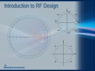
- 24. Digitally Modulated Waveforms 01.04.2014 24 QPSK
- 25. Signal Processing • Typically used in receivers • Gives the receiver the ability to be “adaptable” • The bandwidth or filter characteristics can be tailored to current conditions • Maintains signal levels and optimal use of the channel • Transmission channel changes dramatically due to conditions and motion “equalization” • Modern cellular systems assign different channels specific to immediate needs 01.04.2014 25
- 26. Test and Verification Key Components • Design is complete • Review is complete • Prototype has been built • Verification that system meets specification • Design Verification • Spectrum Analyzer • Signal Generator • Vector Network Analyzer • Power Meter 01.04.2014 26
- 27. Spectrum Analyzer • Basic measurement device required if looking at complex signals or where multiple signals are used. • Basic measurement is frequency vs power • Typically two main types swept tuned and FFT • Modern version have many new capabilities for measuring including: • Noise Figure • Group Delay • Phase Noise • Basic Modulation Analysis • Complex Modulation Analysis for: • Mobile Wireless • Wireless LAN • Bluetooth • Satellite Communications • RADAR 01.04.2014 27
- 28. Signal Generator • Basic measurement device required to generate simple and complex input signal • Basic use is a Sin wave at different power levels and frequencies • Two main types analog and vector • Modern version have many new capabilities for generating complex signals including: • AM, FM, PM • Arbitrary signals generated mathematically • Frequency hopping signals • Complex Modulation Signals including: • Mobile Wireless • Wireless LAN • Bluetooth • Satellite Communications • RADAR 01.04.2014 28
- 29. Vector Network Analyzer • More complex measurement device used to stimulate and measure amplitude and phase response of high frequency devices. • Basic use is stimulate a device such as an amplifier with a Sin wave and measure the amplitude and phase response • Modern version have many new capabilities for measuring more complex devices such as: • Mixers or converters • Multiport devices up to 48 ports 01.04.2014 29
- 30. Power Meter • Most basic measurement device • Measures power level coming out of devices • Typically two types • Diode Based – higher dynamic range, fast • Thermistor Based – most accurate but lower dynamic range • Gives no information as to frequency content • Newer power meters typically include sensor with PC software based measurement unit • Can use in conjunction with a signal generator to get basic frequency response of devices • Modern versions have ability to measure pulsed or bursed signals 01.04.2014 30
- 31. Putting it all together 01.04.2014 31
- 32. Conclusion • This is intended to be the first in a series of courses on the process of RF system design. • RF system design is a complex process beginning with a detailed understanding of many things such as: • Operating environment • Size, weight, power • What information to be sent • One-way or two way • Stationary or moving • Target Cost • Available spectrum or frequency • After a system is conceptualized, it is typically simulated • Finally a prototype needs to be built and its performance validated 01.04.2014 32