An introduction to pressure vessels
•
0 gefällt mir•406 views

This document provides an overview of pressure vessels, including their definition, classifications, materials, and design considerations. Pressure vessels are closed containers designed to hold gases or liquids above atmospheric pressure. They are commonly used in industries like petroleum refining, chemicals, power generation, and food and pharmaceuticals. Key aspects covered include vessel geometry, installation, thickness calculations, testing requirements, and applicable codes and standards like the ASME Boiler and Pressure Vessel Code.

Empfohlen
Weitere ähnliche Inhalte
Was ist angesagt?
Was ist angesagt? (20)
Ähnlich wie An introduction to pressure vessels
Ähnlich wie An introduction to pressure vessels (20)
Kürzlich hochgeladen
Kürzlich hochgeladen (20)
An introduction to pressure vessels
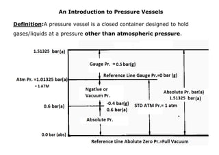
- 1. An Introduction to Pressure Vessels Definition:A pressure vessel is a closed container designed to hold gases/liquids at a pressure other than atmospheric pressure.
- 2. Pressure vessels used in: Petroleum refining plant Chemical plant Power plant Food Industries Pharmaceuticals Industries Classification of Pressure vessels Based on Geometry: Spherical (Most Economical due to lower thickness), Rectangular (Most Costly due to higher thickness), Cylindrical (Easy Manufacturing). Based on Installation: Horizontal, Vertical, Inclined. Based on Pressure: Internal, External, Both (Jacketed vessels) Based on Wall thickness: Thin wall(R/t >=10), Thick wall (R/t <10)
- 3. Based on Method of Manufacturing: Welded:It is a fabrication process that joins metalsby producing arc between base metal and electroderesulting hightemperature (melting point)causing base metalto join by fusion. Forged:Forging is a manufacturing process in which metal is heated to plastic limit and reshaped using external load.This method is used generally for High pressure vessels where shell/Head/SRN nozzles with flange etc. are made by forging to avoid welding. Brazed:Brazing is a manufacturing process in which low melting point filler metal used to join base metals, which do not melt the base metal. Metal-joining techniques such soldering (Exp. Plate Heat Exchangers). Based on Material: Ferrous i.e. Carbon Steel, Low Alloy Steel, Stainless steel, Duplex SS Non Ferrous i.e. Copper Alloys (Monel), Nickel alloys (Hastalloy). Non Metallic i.e. Fiber Reinforced Plastics (FRP) Based on Usage: Static, Mobile
- 4. Tall Tower/Column Vertical vessel with Height (TL to TL) / Diameter ratio > 5is considered as Column. Loading Condition: Erection:un-corroded, erected on foundation, without insulation, platforms, trays etc. Only welded attachments & full wind on column. Operating: corroded, under design pressure, including welded items, trays, insulated including all attachments shall be considered.
- 5. Test: Column (corroded) under test pressure, filled with water plus 33% of specified wind load on un-insulated column including all attachments shall be considered. (iv) Earth quake And Wind Shall Be Considered Not Acting Concurrently. Deflection of Column Maximum allowable deflection at top of column shall be equal to column height / 200. Dynamic Analysis of Columncarried out for transverse wind induced vibrations.
- 6. Reactor:Process fluid undergoes a chemical reaction. Reaction rate is increased by catalyst. Packed bed reactors are most commonly used.Cylindrical vessel packed with catalyst. Support grid and screen is placed at the bottom to support the catalyst.
- 7. SPHERICAL VESSEL: The spherical shape has the Highest Volume/Surface area and less metal is needed to make the vessel. So, it’s a most economical shape. The spherical shape is the strongest shapeagainst internal/external pressure Mostly used for high pressure storage applications.
- 8. t = P*ri/Sh where, P = ρgh t = P*ri/Sh = ρ*9.806*(h-0.3)*D/2*Sh For Atm Pressure only. For Low pr.refer Appendix F. Storage Tank: As per The American Petroleum Institute(API 650), Design Pressure ATM to 3.5 kN/m2. Shell thickness calculation shall be carried out by1-foot method for tank diameters less than and equal to 60m (200 feet).
- 9. Vessel with Jacket: Conventional Jackets: Best forsmall volume vessels (up to 300 gallons),Steam/Gas heating and high- internal pressure applications where internal pressure is double than jacket pressure. If ratio less than two external jacket pressure governs which may cause increase in inner vessel thickness.
- 10. Half pipe: Half pipe are recommended for high- Pressure (up to 750 psig) &High temperature. It is mainly used forliquid heat-transfer application. Dimple jacketed: Most Economical due to pitched ligament joints. Used up to 300 psig.
- 11. Component of Pressure Vessel Shell, Head, Nozzles, Flanges, Supports, Platform/Ladder.
- 13. Hoop or circumferential Stress: Pr. Force = pr. x Projected Area = Pr*d*L Material Resisting Force = Sh*2*L*t (At equilibrium both equal) Pr*d*L = Sh*2*L*t Sh = Pr . d / 2*t or t = Pr.*R/Sh Longitudinal Stress:Pr. Force = pr. x Projected Area = Pr* pi*d2 /4 Material Resisting Force =SL*pi*d*t(At equilibrium both Equal)pr* pi*d2/4 = SL*pi*d*tSl=Pr*d/4*t or t =Pr*R/2*SL
- 14. Codes & Standards: Code/STD Scope Pressure Temp. Special Condition API 650 Internal pressures not exceeding 2.5 psig 0 to 93 deg C entire bottom is uniformly supported API 620 Internal pressure exceed 2.5 psig but not Exceeding 15 psig maximum design temperature Between - 45°C to 121°C Above ground storage tanks including flat-bottom tank that have a single vertical axis of revolution. ASME SEC. VIII - DIV. 1 Internal pressures Between 1.01325 Barg (15 psig) to 206 Barg (3000 psig) Flash point of content at atmospheric pressure is 85 deg C or higher. Not Applicable for inside diameter, width, height, or cross section diagonal below 6" ASME SEC. VIII Div. 1 =<3000 psigDiv. 2 =< 10000 psigDiv. 3. ASME SEC. IIA &IIBMaterial SpecificationsFerrous (SA-516 70, SA-105) Non Ferrous (Monel SB-127, SB-165), Manufacturing requirements, Chemical Properties. ASME SEC. IIC Specifications for Welding Rods, Electrodes, and Filler Metals ASME SEC. IID Material Properties, Mechanical/Physical Properties. ASME SEC.V NDT requirementsRT, MP, DP, UT etc. ASME SEC. IXQualification Standard for Welding etc. Welding Procedure Specification (WPS), Procedure Qualification Record (PQR) Welding Performance Qualification (WPQ) TEMA(Tubular Exchanger Manufacturer Association). Shell & Tube HX. Supporting StandardsASME B16.5, B16.20, B16.9, B16.11, Wind & Seismic
- 15. ASME Code, Section VIII, Division 1 use the maximum principal stress theory as a basis for design. This theory simply considers that yielding occurs when the largest principal stress equals the yield strength. Minimum Thickness of Pressure Components is 1.5mmexclusive of any corrosion allowance. Design Formulas: Shell design thickness,Tr = PRi/ (SE-0.6P) +C.A Hemi. Head design thickness,Tr = PRi/ (2SE-0.2P) +C.A Elliptical Head design thickness,Tr = PRi/ (SE-0.1P) +C.A Thin Cylindrical Shell: Material of Shell SA-515-60, Internal diameter Di= 96 inch Internal design pressure P= 100 psig(Since P < 0.385SE =6545 psi) Internal design Temperature = 450 F°. Allowable Stress at design Temp.S= 15,000 psi (ASME Sec. II, Table 1A) Corrosion allowance C.A= 0.125 in. Joint efficiency is E = 0.85. Corroded Radius Ri=Di/2+C.A = 96/2+0.125 = 48.125 inch.
- 16. Shell design thickness, Tr = PRi/ (SE-0.6P) +C.A = 100 x 48.125 + 0.125 =0.504 inch (15,000 x 0.85 – 0.6 x 100) Hemispherical Head design thickness, Tr = PRi/ (2SE-0.2P) +C.A = 100 x 48.125 + 0.125 =0.314 inch (2 x15,000 x 0.85 – 0.2 x 100) Elliptical Head design thickness, Tr = PRi/ (SE-0.1P) +C.A = 100 x 48.125 + 0.125 =0.503 inch (15,000 x 0.85 – 0.1 x 100) Hydrostatic Test Pressure: Pressure per UG99b = 1.3 * M.A.W.P. * Sa/S kgf/cm² gPressure per UG99c = 1.3 * M.A.P. - Head(Hyd) kgf/cm² g Pressure per UG100 = 1.1 * M.A.W.P. * Sa/S kgf/cm² g
- 17. Weld Category:
- 19. Nozzle ReinforcementIt works on the basis of replacement of opening c/s with equal c/s area in shell/Nozzle/fillet welds.
- 20. Local loads on vessel due to piping
- 21. WRC 107/WRC-537(Accurate) WRC 297 Applicable for cylindrical & spherical shells. Analyzes cylindrical or rectangular attachments which can be rigid or hollow. Applicable cylindrical shell Intersectingeach other. Analyzes cylindrical hollow attachments Boundary conditions d/D<0.33 Dm/T>50 Boundary conditions d/D<=0.5, d/t>=20 up to d/t<=100 D/T>=20 up to D/T<=2500, d/T>=5 Nozzle must be isolated Considers no opening in shell. Considers circular opening in shell. Calculates only the vessel stresses. Calculates Vessel stresses &nozzle stresses. Methods of reducing local stresses in Vessel. 1. Increase the size of the attachment. (forLug/Leg Support, Lifting Lug etc.) 2. Increase the number of attachments. (forLug/Leg Support,Lifting Lug etc.) 3. Change the shape of the attachment to distribute stresses. (To cover higher surface area) 4. Add reinforcing pads.(for Nozzles Lug/Leg Support,Lifting Lug etc.) 5. Increase shell thickness locally or use thicker shell course.(for Nozzles)
- 22. Material of ConstructionStress Strain Diagram:
- 25. Impact & Hardness test methods:
- 26. Vessel in Hydrogen & H2S service: hydrogen atoms in a solid metal dissolved in the metal grid and accumulate between Iron atoms results in the reduction of its ductility by decreasing the energy of cohesion and consequently in the increase of its probability of brittle fracture.
- 28. Heat Exchanger is a device for transferring heat from one medium to another in a direct or indirect contact.
- 30. Fixed type Shell & Tube Heat Exchanger AEM BEM Construction:Non- removable Bundle, Fixed Tubesheets Advantages: Less costly than removable bundle heat exchangers. Provides maximum heat transfer surface per given shell and tube size. Provides multi-tube-pass arrangements. Limitations: Shell side can be cleaned only by chemical means. Higher Differential thermal expansion between shell and tubesrequires Bellow.
- 31. U-Tube type Shell & Tube Heat Exchanger AEU BEU CEU Construction:Removable Bundle, U-Tube Advantages: Less costly than floating head designs. Provides multi-tube pass arrangements. Allows for differential thermal expansion between the shell and tubes &individual tubes. High surface per given shell and tube size. Capable of withstanding thermal Limitations: Tube side cleaned by chemical means only. Individual tube replacement is not practical. Cannot be made single pass on tube side. Tube wall at U-Bend is thinner than at straight portion of the tube. Draining tube side difficult in vertical (head up) position.
- 32. shock. Floating Head type Shell & Tube Heat Exchanger AES BES CES Construction:Removable Bundle, Floating Head Cover Advantages: Allows for differential thermal expansion between the shell & tubes. Limitations: Higher maintenance cost. More costly than fixed tube sheet or U-
- 33. Excellent Inflammable and/or toxic service tube heat exchanger designs.
- 34. ASME Sec. VIII Div.1 Appendix 13-Air Cooled Heat Exchanger: Air Cooled Heat Exchangers Advantages Limitations Attractive option for locations where cooling water is not available or expensive to treat. High initial purchase cost due to relatively large area occupied.
- 35. Low maintenance and operating costs (typically 30-50% less than cooling water) Higher process outlet temperature (10-20 oF above the ambient dry bulb temperature)