The document discusses positive temperature eutectic (PCM) thermal energy storage systems. It begins by explaining the disadvantages of conventional water-ice storage systems, which require low-temperature chillers. The document then introduces positive temperature eutectic solutions, which can freeze and melt above 0°C, overcoming these disadvantages. Various PCM mixtures are presented, along with encapsulation techniques to contain them. The document argues that PCM storage enables higher evaporator temperatures and lower condenser pressures, improving energy efficiency. A variety of applications are proposed, including utilizing chilled water and refrigeration temperature ranges for charging.
Advantages of Hiring UIUX Design Service Providers for Your Business
PCM Thermal Energy Storage Systems; Ashrae 2004 Conference Paper
1. VENUE
ASHRAE 2004, ANAHEIM WINTER MEETING
TITLE
POSITIVE TEMPERATURE EUTECTIC (PCM)
THERMAL ENERGY STORAGE SYSTEMS
AUTHORS
Zafer URE M.Sc., C.Eng., MCIBSE, MASHRAE, M.Inst.R, MIIR
Environmental Process Systems Limited
Unit 32, Mere View Industrial Estate, Yaxley, Cambridgeshire, PE7 3HS, U.K.
Tel: +44-(0)-1733 243400, Fax: +44-(0)-1733 243344,
e-mail: z.ure@epsltd.co.uk, www.epsltd.co.uk
Synopsis;
Thermal Energy Storage (TES) may be considered as a useful tool to reduce the
number of refrigeration machinery by means of spreading the daytime load over
24 hours period. Hence, any type of TES systems can be consider as useful tool to
reduce the overall environmental impact for a given cooling application.
Water / Ice TES has the advantage of universal availability, low cost and transport
ability through other system components. However, a conventional water based
TES system for air conditioning application requires low temperature chillers and
therefore standard water chillers must be replaced with low temperature glycol
chillers which operate with a lower evaporation temperature.
The disadvantages of a conventional HVAC chiller and ice (water ice) storage
system can be overcome by utilising the latent heat capacity of various “Eutectic”
mixtures without the need for minus circulation temperatures. Plus temperature
thermal energy storage PlusICE not only enables the designer to utilise existing
chiller technology, but also this technique enables charging process to take place
possibly by means of free cooling, i.e. without running the chillers.
This paper is extended to investigate the alternative TES systems in the form of
Eutectic PlusICE Solutions. The results of performance tests for various
temperature ranges as well as the practical application guidance are also
incorporated as part of this paper.
Keywords;
(C.O.P) Co-efficiency of Performance, (TES) Thermal Energy Storage
(HVAC) Heating Ventilation Air Conditioning,
(PCM) Phase Change Materials, Eutectic, PlusICE , CO2 Carbon Dioxide
ASHRAE-2004-4.doc
2. 1.0 - BACKGROUND
Energy usage, economical and environmental issues are becoming the focal points for both
end users and the public at large. Current trends towards privatisation and an open market
approach for utility companies has created a new kind of energy market whereby the period of
energy usage and the type of energy used is becoming the main criteria for price structuring (1 )
rather than overall energy consumption.
Hence, current building services must be designed to provide sufficient flexibility for load
shifting and energy usage control in order to achieve the most economical operation. A
Thermal Energy Storage technique whereby " Storing High or Low Temperature energy
for later use in order to bridge the time gap between energy availability and energy use "
can be considered as a useful tool to achieve this aim.
Unfortunately HVAC & Refrigeration TES applications utilise water ice which can only be
produced with low temperature chillers. As a result, the benefits of night time low ambient
temperature, existing water chillers and possibly free ambient cooling options cannot be fully
utilised.
If we can offer designers ICE which freezes and melts above 0°C (32 °F) this product will
open new horizons for environmentally friendly and economical systems for both New and
Retrofit type process cooling / heating load shifting applications.
This paper investigates Positive Temperature Eutectic Solutions for long term TES usage to
achieve the above aim. Relevant application guidance along with typical application
examples are also incorporated within this paper.
2.0 - THERMAL ENERGY STORAGE:
Thermal Energy Storage bridges the time gap between energy requirement and energy use. A
thermal storage application may involve a 24 hour or alternatively a weekly or seasonal
storage cycle depending on the system design requirements. Whilst the output is always
thermal, the input energy may be either thermal or electrical.
In full storage systems, the entire design load for the design day is generated off peak and
stored for use during the following peak period. In partial storage systems, only a portion of
the daily load is generated during the previous off peak period and put into storage. During
the peak period, the load is satisfied by a simultaneous balancing operation of the installed
machinery and stored energy in order to satisfy the overall daily design duty.
2.1 - Storage Medium:
For HVAC and refrigeration application purposes, water and phase change materials (PCM)
constitute the principal storage media. Water has the advantage of universal availability, low
cost and transport ability through other system components. However, a conventional water
based TES system for air conditioning applications require low temperature chillers and
therefore standard water chillers must be replaced with low temperature glycol chillers which
operate at lower evaporation temperatures ( 2 ) .
ASHRAE-2004-4.doc
3. 2.2 Current Ice Production Technology :
Ice production techniques can be divided into two main groups namely Dynamic and Static
systems ( 3 ) as shown in Table 2.2.1. The ice produced can be used either directly to chill
products such as fish, vegetables, meat, poultry etc. or indirectly as a secondary coolant for a
latent heat cooling effect for process cooling such as ice storage, TES systems for air
conditioning and process cooling as a secondary cooling medium.
STATIC ICE PRODUCTION DYNAMIC ICE PRODUCTION
1 - Ice Builders 1 - Plate Harvester
2 - Ice Banks 2 - Tube Harvester
3 – Encapsulated Ice Modules 3 - Flake Ice Machines
a) Balls 4 - Binary Ice Machines
b) Flat Containers
Table 2.2.1 - Current Ice Production Technology
3 - POSITIVE TEMPERATURE EUTECTIC TES SYSTEMS :
Positive Temperature Eutectic Solutions are mixtures of two or more chemicals which, when
mixed in a particular ratio, have a freezing / melting point above water freezing temperature of
0°C (32 °F) and they offer a thermal energy storage facility between +4 °C (39 °F) and +117
°C (242 °F).
Eutectics are well-known and in fact early applications date back to the late 18th century
however the separation and the life expectancy of these mixtures were unpredictable and
therefore their wide spread usage was limited.
The disadvantages of a conventional HVAC chiller and ice (water ice) storage system can be
overcome by utilising the latent heat capacity of various “Eutectic” mixtures without the need
for minus circulation temperatures.
Positive temperature thermal energy storage “PlusICE” not only enables the designer to
utilise existing chiller technology but also enables charging by means of free cooling ( 4 ) , i.e.
without running the chillers
Although the term “Eutectic” is widely used to describe the materials we are interested in, a
better description would be “Phase Change Materials” (“PCMs”). Unfortunately, very few of
the documented PCMs (a number of which are listed in Table 3.1) (5) are true Eutectics and
so many have to be modified to obtain a material suitable for long term use.
ASHRAE-2004-4.doc
4. Material Melt Heat of Latent
Point Fusion Heat
(ºC) ( ºF) kJ/kg Btu/Lb MJ/m3 Btu/Lb
MgCl2.6H2O 117 243 169 73 242 6,499
Mg(NO3)2.6H2O 89 192 163 70 252 6,768
CH3COONa.3H2O 58 136 226 97 287 7,708
MgCl2.6H2O/ 58 136 132 57 201 6,499
Mg(NO3)2.6H2O
Na2HPO4.12H2O 34 93 265 114 379 10,179
Na2SO4.10H2O 32 90 251 108 335 8,997
Na2CO3.10H2O 32 90 233 100 340 9,131
Waxes 28 to 82 to 220 to 94 to 170 to 4,564
4 39 245 105 195 to
5,237
Polyethylene 28 to 82 to 146 to 62 to 165 to 4,431
glycols -15 -9 155 66 175 to
4,699
CaCl2.6H2O 27 81 191 82 298 8,003
Glauber’s salt + 24 to 75 to wide wide wide wide
additives 4 39 range range range range
CaCl2.6H2O/ 15 59 140 60 249 6,687
CaBr2.6H2O
Water 0 32 335 144 335 8,997
Range of 0 to 32 to Wider Wider wide wide
water/salt -64 -83 range range range range
Eutectics
Table 3.1 - Range of commonly used PCMs
PCMs can be broadly grouped into two categories; ”Organic Compounds“ (such as
polyethylene glycol) and “Salt-based Products” (such as Glauber’s salt). Each group of
PCMs comes with advantages and disadvantages some of which are listed in Table 3.2 ( 4 ).
Advantages Disadvantages
Simple to use Generally more expensive
Non-corrosive Lower latent heat/density
No supercooling Often give quite broad melting range
ORGANIC No nucleating agent Can be combustible
Generally cheap Need careful preparation
Good latent heat/density Need additives to stabilise for long
Well defined phase change term use
SALT-BASED temperature Prone to supercooling
Non-flammable Can be corrosive to some metals
Table 3.2 - Characteristics of PCMs
ASHRAE-2004-4.doc
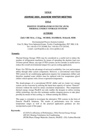
5. The fundamental requirement for a Modified Eutectic Solution can be classified in three
categories, namely stable solution ( no separation or degrading), minimum supercooling /
heating and finally close freezing and melting temperatures as illustrated in Figure 3.1.
Freezing Curve Melting Curve
Temperature
Freezing &
Melting Region
(2)
(1)
Super Cooling/
Heating Zone
Time
Figure 3.1 - Eutectic PCM Freezing / Melting Curve
There are three fundamental additives commonly used to modify Eutectic solutions covered
in Table 3.1 for long term use. The first additive is Nucleating Agentx which encourages
Crystal formation and therefore minimises super cooling and the second additive is Freeze
Depressant to achieve a lower phase change temperature/.The third and final additive is the
Gelling / Thickening Agent in order to overcome separation and degrading problems.
Once the above components have been carefully applied, a satisfactory Eutectic Solution can
be produced from the physical and thermodynamic point of views and commercially available
solutions are incorporated in Table 3.3.
However, majority of suitable PCM solutions for HVAC and refrigeration systems are
corrosive to commonly used pipe and line components and therefore a suitable encapsulation
techniques must be applied to overcome this problem while providing the best thermal
performance. Various encapsulation techniques such as tube, flat container or alternatively
ball concepts have been developed whereby the PCM solution is encapsulated in plastic and /
or metal shell as illustrated in Figure 4.2 (4 ).
llaB
llaB lleC
lleC maeB
maeB
EPIP RENNI
LAES LACINAHCEM
NOITULOS CITCETUE
EBUT RETUO
NRUTER
Figure 4.2 - PlusICE PCM Beam Concept
ASHRAE-2004-4.doc
6. The heat transfer between the surrounding media, which flows around or inside the unit and
the surrounding PCM solutions, takes place from the outer or inner or the combination of
both surfaces of the encapsulated PCM unit. These techniques are generally eliminates the
contamination risk and offers an efficient, cost effective, practical and flexible new type of
TES designs.
5 - TES AND ASSOCIATED ENERGY EFFICIENCY:
Irrespective of the type of refrigerant used, it is vital to improve the energy efficiency for any
given refrigeration system in order to achieve an environmentally friendly design. Every
compression refrigeration cycle operates between the discharge and suction pressure
envelope, which dictates the cycle shown in Figure 5.1.
BASIC REFRIGERATION CYCLE
PRESSURE (Barg)
Pc SUB-COOLING CONDENSER
EXPANSION
VALVE COMPRESSOR
Pe
SUPER -HEATING
EVAPORATOR
ENTHALPHY (KJ/kg)
Figure 5.1- Cardinal Rule for the Refrigeration Energy Efficiency
The efficiency of the cycle can be improved by utilising different types of refrigerant,
compressor, condensing, evaporating and expansion devices, but the cardinal rule of energy
efficiency dictates that “lower condensing pressures and higher evaporation temperatures
lead to less energy consumption for a given refrigeration duty” therefore designers should
aim to achieve the above requirement within the design limits for a given system.
If a Positive Temperature Eutectic Thermal Energy Storage system is incorporated as part of
the cycle, it offers the following energy efficiency features;
* Higher evaporation temperature during TES charging leads to less power consumption.
* Lower condensing pressure reduces the compressor power consumption.
* Free sub-cooling TES increases the cooling capacity and the overall COP.
* Superheat control TES improves the compressor operation.
* Lower nighttime ambient conditions may offer free TES charging.
ASHRAE-2004-4.doc
7. 6.0 - PlusICE APPLICATIONS ;
Positive Temperature Eutectic Solutions between +4 °C and +117 °C can not only be charged
using conventional water chillers and the temperature range also offers the following
additional TES applications for a cost effective energy management concept for both New
and Retrofit type process cooling / heating load shifting applications.;
* Absorption & Co-Generation.
* Cooling Tower / Dry Cooler Circuit Load Shifting.
* Heat Recovery / Solar Heating Systems.
• Free Ambient Cooling Circuit.
The beam design shown in Figure 4.3 can be filled with any of the proposed PCM solutions
in Table 4.1. The positive temperatures offered by this concept opens a revolutionary new
way of thermal energy storage whereby designers can utilise conventional chilled water and
refrigeration temperature ranges to charge the TES system.
Furthermore, the heat rejection side of the refrigeration cycle, free cooling and heat recovery
TES concepts can also be incorporated in order to minimise the maximum demand charges
and energy consumption of the system.
A possible combination of the proposed beam concept for both HVAC and refrigeration side
of the system is incorporated in Figure 6.1 ( 4 ).
V VV V PlusICE Concept
PlusICE
Condenser
HEAT
REJECTION
SYSTEM
Condenser Water
Chiller
Receiver
Receiver
Compressor
HVAC Evaporator
Evaporator
Figure 6.1 - PlusICE PCM Beam Applications
ASHRAE-2004-4.doc
8. A carefully balanced positive temperature thermal energy storage system enables designers to
control the refrigeration envelope shown in Figure 5.1 and therefore the size of the
refrigeration machinery can be reduced as a result of an optimum energy balance.
In particular, the possibility of a Free Cooling Circuit, Absorption chillers ( 6 ) , Co-
Generation, Solar ( 7 ), Hot Water and Heat Recovery TES charging may result in further
reduction of refrigeration machinery and unmatched cost effective TES installations for both
new and retrofit applications.
The relevant positive temperature TES against a conventional low temperature chiller Ice
Storage charging operations are illustrated for Air and Water Cooled chiller operations over
a range of operating temperatures in Figure 6.2 and Figure 6.3 respectively.
20 25 30 35 40 45
Ambient Air Temperature (C)
4.50
PlusICE CH ARGING
4.00
DAY CHILL ER
ICE BUILD
Chiller COP
3.50
3.00
2.50
2.00
4 0 -2 -4 -6 -8
Glycol Le aving Te m pe ratur e (C)
Figure 6.2 - Air Cooled Chiller PlusICE Vs Conventional Ice Charging Comparison
30 35 40 45 50 52
5.00
C ondenser Leaving W ater Temperature (C )
4.50 PlusICE CH ARG ING
4.00
Chiller COP
DA Y CH IL L ER
ICE B U IL D
3.50
3.00
2.50
2.00
4 0 -2 -4 -6 -8 -10
Glycol Leaving Temperature (C)
Figure 6.3 - Water Cooled Chiller PlusICE Vs Conventional Ice Charging Comparison
ASHRAE-2004-4.doc
9. Low ambient temperatures coupled with higher evaporation temperatures offer a significant
overall COP improvement, which is in the region of 16-46 % depending on the type of unit
and location. A similar benefit can also be achieved if we apply a Positive Temperature TES
for the high temperature i.e. heat rejection side of the system. A conventional design must
cater for the peak ambient conditions which occur only a few days or weeks of the year (8).
Typical UK annual average daily wet and dry bulb temperatures as well as standard design
levels are illustrated in Figure 6.4 ( 9 ).
30
28
26
24
22
Temperature (Deg C)
20
18
16
14
12
10
8
6
4
2
0
JAN
FEB
M AR
APR
M AY
JU NE
JULY
L O N D O N (U K ), AUG
SEP
AVERAGE W EATHER DATA, OCT
(K ew 1 9 4 1 -7 0 ) NO V
DEC
W e t B u lb D r y B u lb D e s ig n
Figure 6.4 - Typical UK Annual Average Ambient Profile Vs Design Ambient
Considering the refrigeration envelope indicated in Figure 5.1, Dry Cooler / Cooling Tower
circuit Heat Rejection TES can be charged by simply utilising low ambient temperatures and
this free charging operation offers a significant energy and load shifting facility by controlling
the Heat Rejection side of the system i.e. Condensing Pressure and effectively controlling the
refrigeration machinery’s energy consumption.
This principal can be applied to both Mechanical Compression and Heat Driven systems and
Figure 6.5 illustrates a typical Heat Rejection TES operation for a water cooled chiller and the
study indicates that the day time peak energy consumption can be reduced by as much as
33% simple by utilising the night time low ambient. In other words, the day COP
improvement can be achieved without running any refrigeration machinery over night. As a
result, a heat rejection TES offers unmatched efficiency, reduced running cost and an
environmentally friendly concept.
ASHRAE-2004-4.doc
10. 30 35 40 45 50 52
C ondenser L eaving W ater T em perature (C )
5.00
4.50 3
4.00
C hiller D ay O peration
Chiller COP
2
3.50 1
3.00
2.50
2.00
4 0 -2 -4 -6 -8 -10
Glycol Le aving Te m pe rature (C)
C O P Im provem en t b y P lu sIC E T E S L oad S hifting
ent h ifting
1) 5 o C R E D U C T IO N 13 % C O P IM P R O V E M E N T
2) 10 o C R E D U C T IO N 23 % C O P IM P R O V E M E N T
3) 15 o C R E D U C T IO N 33 % C O P IM P R O V E M E N T
Figure 6.5 - Water Cooled Chiller PlusICE Heat Rejection TES Impact on COP.
7.0 - CONCLUSION:
Modern society’s reliance on refrigeration and air conditioning indicates that refrigeration and
the associated environmental issues will be with us for a considerable time and therefore one
has to utilise existing and available alternative technologies with minimum usage of energy.
A Positive Temperature Eutectic “ PlusICE “ Thermal Energy Storage not only provides the
end user with an Environmentally Friendly design but also the following additional benefits
can be obtained:
• Reduced Equipment Size
• Capital Cost Saving
• Energy Cost Saving
• Environmentally Friendly Installation
• Improved System Operation
• Flexibility for the Future Capacities
The temperature ranges offered by the proposed PCM solutions utilise conventional chilled
water temperature ranges for both the charging and discharging sides of the system. Hence,
they can be applied to any new or retrofit application with minimal technical and economical
impacts.
Furthermore, the possibility of Free Cooling Cycle, Absorption Chillers, Co-Generation,
Solar, Hot Water and Heat Recovery TES system combinations offer new horizons for
designers to control the energy balance to match the load and electricity demand /
consumption of the system as a whole.
The task for designers is to explore all available technologies towards achieving improved
efficiency regardless of which refrigerant is used, and apply where and when possible
diversification technologies in order to minimise the overall CO2 emission related to energy
usage. A carefully balanced PlusICE Thermal Energy Storage may be the answer for some of
the cooling applications for an Environmentally Friendly and Economical alternative.
ASHRAE-2004-4.doc
11. 8.0 - REFERENCES:
1- Beggs C., Ure Z . “Environmental Benefits of Ice TES in Retailing Application”,
CIBSE / ASHRAE Joint National Conference, Part II, Harrogate, Sep. 1996, UK
2- Ure Z . “Thermal Energy Storage in Retailing Application”, CIBSE / ASHRAE
Joint National Conference, Part II, Harrogate, Sep. 1996, UK
3- Ure Z., “Alternative Technology”, Page 20-22, October 1996 Partners in Europe
Issue, RAC Journal
4- Burton G, Ure Z . “Eutectic Thermal Energy Storage Systems” , CIBSE National
Conference, Volume II, Alexandra Palace, Oct. 1997, UK
5- ASHRAE Handbook, “HVAC Systems and Applications “, Issue : 1987, Section 46
6- Ames, D.A., Eutectic Cool Storage: Current Developments, ASHRAE Journal,
April 1990
7- Telkes, M., Solar Energy Storage, ASHRAE Journal, September 1974
8- “Design Ambient Temperatures”, Refrigeration Industry Board, 1985
9- Met Office Data
ASHRAE-2004-4.doc