Weitere ähnliche Inhalte
Ähnlich wie Mcc132 14io1 (20)
Kürzlich hochgeladen (20)
Mcc132 14io1
- 1. MCC132-14io1
3 1 2
6 5
7 4
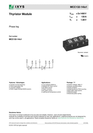
Phase leg
Thyristor Module
Part number
MCC132-14io1
Backside: isolated
TAV
T
V V
1.08
RRM
130
1400
=
V = V
I = A
2x
Features / Advantages: Applications: Package:
● Thyristor for line frequency
● Planar passivated chip
● Long-term stability
● Direct Copper Bonded Al2O3-ceramic
● Line rectifying 50/60 Hz
● Softstart AC motor control
● DC Motor control
● Power converter
● AC power control
● Lighting and temperature control
Y4
● Industry standard outline
● RoHS compliant
● Soldering pins for PCB mounting
● Base plate: DCB ceramic
● Reduced weight
● Advanced power cycling
● Isolation Voltage: V~
3600
Information furnished is believed to be accurate and reliable. However, users should independently
evaluate the suitability of and test each product selected for their own applications. Littelfuse products are not designed for,
and may not be used in, all applications. Read complete Disclaimer Notice at
Disclaimer Notice
www.littelfuse.com/disclaimer-electronics.
IXYS reserves the right to change limits, conditions and dimensions. 20191209c
Data according to IEC 60747and per semiconductor unless otherwise specified
© 2019 IXYS all rights reserved
- 2. MCC132-14io1
V = V
kA²s
kA²s
kA²s
kA²s
Symbol Definition
Ratings
typ. max.
I
V
I A
VT 1.14
R 0.23 K/W
min.
130
V V
200
T = 25°C
VJ
T = °C
VJ mA
10
V = V
T = 25°C
VJ
I = A
T
V
T = °C
C 85
Ptot 435 W
T = 25°C
C
150
1400
forward voltage drop
total power dissipation
Conditions Unit
1.36
T = 25°C
VJ
125
VT0 V
0.80
T = °C
VJ 125
rT 1.5 mΩ
V
1.08
T = °C
VJ
I = A
T
V
150
1.36
I = A
300
I = A
300
threshold voltage
slope resistance
for power loss calculation only
µA
125
V V
1400
T = 25°C
VJ
I A
300
PGM W
t = 30 µs 120
max. gate power dissipation P T = °C
C 125
W
t = 60
P
PGAV W
8
average gate power dissipation
CJ 211
junction capacitance V = V
400 T = 25°C
f = 1 MHz
R VJ pF
ITSM t = 10 ms; (50 Hz), sine T = 45°C
VJ
max. forward surge current
T = °C
VJ 125
I²t T = 45°C
value for fusing
T = °C
125
V = 0 V
R
V = 0 V
R
V = 0 V
V = 0 V
t = 8,3 ms; (60 Hz), sine
t = 10 ms; (50 Hz), sine
t = 8,3 ms; (60 Hz), sine
t = 10 ms; (50 Hz), sine
t = 8,3 ms; (60 Hz), sine
t = 10 ms; (50 Hz), sine
t = 8,3 ms; (60 Hz), sine
VJ
R
VJ
R
thJC thermal resistance junction to case
T = °C
VJ 125
4.75
5.13
81.6
79.1
kA
kA
kA
kA
4.04
4.36
112.8
109.5
1400
500 µs
RMS forward current
T(RMS)
TAV
180° sine
average forward current
(di/dt)cr A/µs
150
repetitive, I =
TVJ = 125°C; f = 50 Hz
critical rate of rise of current
VGT
gate trigger voltage V = 6 V T = °C
25
(dv/dt) T = 125°C
critical rate of rise of voltage
A/µs
500
V/µs
t = µs;
I A; V = ⅔ V
R = ∞; method 1 (linear voltage rise)
VJ
D VJ
500 A
T
P
G = 0.5
di /dt A/µs;
G = 0.5
DRM
cr V = ⅔ VDRM
GK
1000
2.5 V
T = °C
-40
VJ
IGT gate trigger current V = 6 V T = °C
25
D VJ 150 mA
T = °C
-40
VJ
2.6 V
200 mA
VGD
gate non-trigger voltage T = °C
VJ 0.2 V
IGD
gate non-trigger current 10 mA
V = ⅔ V
D DRM 125
latching current T = °C
VJ 300 mA
IL 25
t µs
p = 30
I A;
G = 0.5 di /dt A/µs
G = 0.5
holding current T = °C
VJ 200 mA
IH 25
V = 6 V
D R = ∞
GK
gate controlled delay time T = °C
VJ 2 µs
tgd 25
I A;
G = 0.5 di /dt A/µs
G = 0.5
V = ½ V
D DRM
turn-off time T = °C
VJ 150 µs
tq
di/dt = A/µs
10 dv/dt = V/µs
20
V =
R 100 V; I A;
T = 160 V = ⅔ VDRM
t µs
p = 200
non-repet., I = 160 A
T
100
RthCH 0.1
thermal resistance case to heatsink K/W
Thyristor
1500
RRM/DRM
RSM/DSM max. non-repetitive reverse/forward blocking voltage
max. repetitive reverse/forward blocking voltage
R/D reverse current, drain current
T
T
R/D
R/D
200
IXYS reserves the right to change limits, conditions and dimensions. 20191209c
Data according to IEC 60747and per semiconductor unless otherwise specified
© 2019 IXYS all rights reserved
- 3. MCC132-14io1
Ratings
Part Number
yywwAA
Date Code (DC)
+
Production
Index (PI) Lot.No: xxxxxx
Data Matrix: part no. (1-19), DC + PI (20-25), lot.no.# (26-31),
blank (32), serial no.# (33-36)
Circuit
Package
Top °C
MD
Nm
2.75
mounting torque 2.25
TVJ °C
125
virtual junction temperature -40
Weight g
150
Symbol Definition typ. max.
min.
Conditions
operation temperature
Unit
MT
Nm
5.5
terminal torque 4.5
V V
t = 1 second
V
t = 1 minute
isolation voltage
mm
mm
14.0 10.0
16.0 16.0
dSpp/App
creepage distance on surface | striking distance through air
dSpb/Apb terminal to backside
IRMS RMS current 300 A
per terminal
100
-40
terminal to terminal
Y4
Delivery Mode Quantity Code No.
Ordering Number Marking on Product
Ordering
50/60 Hz, RMS; I ≤ 1 mA
ISOL
MCC132-14io1 430560
Box 6
MCC132-14io1
Standard
3600
ISOL
Tstg °C
125
storage temperature -40
3000
threshold voltage V
0.8
mΩ
V0 max
R0 max slope resistance * 0.8
Equivalent Circuits for Simulation T =
VJ
I V0 R0
Thyristor
°C
* on die level 125
IXYS reserves the right to change limits, conditions and dimensions. 20191209c
Data according to IEC 60747and per semiconductor unless otherwise specified
© 2019 IXYS all rights reserved
- 4. MCC132-14io1
g
C-C (1:1)
e
nd
r
j
B-B (1:1)
b
DCB
A (3:1)
c
a
M6
p
f
2.8/0.8
A
o
Dim.
MIN
[mm]
MAX
[mm]
MIN
[inch]
MAX
[inch]
a 30.0 30.6 1.181 1.205
b
c 64.0 65.0 2.520 2.559
d 6.5 7.0 0.256 0.275
e 4.9 5.1 0.193 0.201
f 28.6 29.2 1.126 1.150
g 7.3 7.7 0.287 0.303
h 93.5 94.5 3.681 3.720
i 79.5 80.5 3.130 3.169
j 4.8 5.2 0.189 0.205
k 33.4 34.0 1.315 1.339
l 16.7 17.3 0.657 0.681
m 22.7 23.3 0.894 0.917
n 22.7 23.3 0.894 0.917
o 14.0 15.0 0.551 0.591
p
q 22.8 23.3 0.898 0.917
r 1.8 2.4 0.071 0.041
typ. 0.25 typ. 0.010
typ. 10.5 typ. 0.413
k
h
1 2 3
4
5
6
7
n m l
1
1
1
0
8
9
q
i
C C
B
B
Optional accessories for modules
Keyed gate/cathode twin plugs with wire length = 350 mm, gate = white, cathode = red
Type ZY 180L (L = Left for pin pair 4/5)
Type ZY 180R (R = Right for pin pair 6/7) UL 758, style 3751
3 1 2
6 5
7 4
Outlines Y4
IXYS reserves the right to change limits, conditions and dimensions. 20191209c
Data according to IEC 60747and per semiconductor unless otherwise specified
© 2019 IXYS all rights reserved
- 5. MCC132-14io1
0 25 50 75 100 125 150
Ta [°C]
TC [°C]
t [ms]
t [s]
0.001 0.01 0.1 1
0
1000
2000
3000
4000
0
1
1
104
105
106
0 25 50 75 100 125 150
0
40
80
120
160
200
240
280
320
ITSM
[A]
ITAVM
[A]
0 50 100 150 200 250
0
40
80
120
160
200
240
280
320
360
400
Ptot
[W]
ITAVM [A]
0 25 50 75 100 125 150
0 100 200 300 400 500
0
200
400
600
800
1000
1200
1400
I2
dt
[A2
s]
TVJ = 45°C
180° sin
120°
60°
30°
DC
TVJ = 125°C
50 Hz
80% VRRM
TVJ = 45°C
TVJ = 125°C
RthKA K/W
0.3
0.4
0.5
0.6
0.8
1.0
1.4
1.8
Ptot
[W]
IdAVM [A] Ta [°C]
B6
Circuit
3xMCC132 or
3x MCD132
Fig. 1 Surge overload current ITSM,
IFSM: Crest value, t: duration
Fig. 2 I
2
t versus time (1-10 ms) Fig. 3 Max. forward current
at case temperature
Fig. 4 Power dissipation vs. on-state current & ambient temperature
(per thyristor or diode)
Fig. 5 Gate trigger characteristics
Fig. 6 Three phase rectifier bridge: Power dissipation versus direct
output current and ambient temperature
Fig. 7 Gate trigger delay time
180° sin
120°
60°
30°
DC
RthKA K/W
0.2
0.08
0.1
0.15
0.04
0.06
0.03
0.3
0.01 0.1 1 10
0.1
1
10
100
0.01 0.1 1 10
0.1
1
10
100
IG [A]
VG
[V]
IG [A]
TVJ = 25°C
tgd
[μs]
IGT (TVJ = -40°C)
IGT (TVJ = 0°C)
IGT (TVJ = 25°C)
125°C
25°C
limit
typ.
tp = 30 µs
tp = 500 µs
PGM = 120 W
60 W
PGAV = 8 W
IGD
Thyristor
IXYS reserves the right to change limits, conditions and dimensions. 20191209c
Data according to IEC 60747and per semiconductor unless otherwise specified
© 2019 IXYS all rights reserved
- 6. MCC132-14io1
0 100 200 300 400
0
400
800
1200
1600
t [s]
10-3
10-2
10-1
100
101
102
103
0.0
0.1
0.2
0.3
0.4
0.5
ZthJC
[K/W]
IRMS [A]
Ptot
[W]
0 25 50 75 100 125 150
Ta [°C]
10-3
10-2
10-1
100
101
102
0.0
0.1
0.2
0.3
0.4
Circuit
W3
3xMCC132 or
3xMCD132
ZthJK
[K/W]
t [s]
DC
180°
120°
60°
30°
Fig. 8 Three phase AC-controller: Power dissipation versus
RMS output current and ambient temperature
Fig. 9 Transient thermal impedance junction to case (per thyristor/diode)
Fig. 10 Transient thermal impedance junction to heatsink (per thyristor/diode)
RthJC for various conduction angles d:
d RthJC [K/W]
DC 0.230
180° 0.244
120° 0.255
60° 0.283
30° 0.321
Constants for ZthJC calculation:
i Rthi [K/W] ti [s]
1 0.0095 0.001
2 0.0175 0.065
3 0.2030 0.400
RthJK for various conduction angles d:
d RthJK [K/W]
DC 0.330
180° 0.344
120° 0.355
60° 0.383
30° 0.421
Constants for ZthJK
calculation:
i Rthi [K/W] ti [s]
1 0.0095 0.001
2 0.0175 0.065
3 0.2030 0.400
4 0.1000 1.290
0.15
0.1
0.08
RthKA K/W
0.2
0.03
0.04
0.06
0.3
DC
180°
120°
60°
30°
Thyristor
IXYS reserves the right to change limits, conditions and dimensions. 20191209c
Data according to IEC 60747and per semiconductor unless otherwise specified
© 2019 IXYS all rights reserved