SlideShare ist ein Scribd-Unternehmen logo
1 von 9
Downloaden Sie, um offline zu lesen
F2006M035
COMPLEMENTARY USAGE OF SIMULATION, WIND TUNNEL AND
ROAD TESTS DURING THE AERODYNAMIC DEVELOPMENT OF A
NEW BMW SUV
Kerschbaum, Hans*
, Grün, Norbert
BMW Group, Germany
KEYWORDS – Aerodynamics, CFD, Simulation, Wind Tunnel, Road Test
ABSTRACT - In the course of the entire vehicle development process aerodynamics is one of
the few disciplines involved from the very early initial phase up to the final serial
development. Along this cycle the available data features very different levels of detail.
After the kick-off of a new model only generic bodies without underhood and underbody
details are provided from styling for the aerodynamic analysis and ranking of different
themes. These may be clay models or virtual shapes created with ALIAS. Once the design
competition is completed and the exterior skin is frozen, more and more details of the engine
compartment and the underbody become available to the aerodynamicist from various other
departments.
According to the growing maturity of product data also the problems to be addressed are
changing. The initial ranking of styling themes with respect to aerodynamic quality is mostly
accomplished purely based on drag and lift distribution. However, aerodynamics is closely
linked with thermal management and therefore cooling air mass flow rates, performance of
the cooling package and component temperatures need to be assessed as soon as the necessary
geometry data is available. Another constraint arises from the short time windows in the
overall development process in which the aerodynamicist can have an impact on the vehicle.
To cope with these tasks the aerodynamicist uses a toolbox consisting of
• Simulation (CFD)
• Wind Tunnel
• Road Test
At the BMW group these tools are not considered as competing instruments, rather they are
used in a complementary fashion. Each tool has its own advantages and drawbacks and
therefore only their clever application to the right problem at the right time delivers a real
benefit and aids to shorten cost and time.
This paper exemplifies this process in detail on the aerodynamic development of a new BMW
SUV to be released in autumn 2006.
INTRODUCTION
The objective of this paper is to describe the complementary usage of simulation, wind tunnel
and road testing during the aerodynamic development of a new SUV.
Aerodynamics is the first engineering discipline to assess properties of styling models and is
further involved throughout the entire development process, see Fig. 1 from (1). Even before
a styling competition starts, various proportion studies are already judged by their potential in
terms of drag and lift forces. During the reduction of different design themes up to styling
freeze, aerodynamics has a significant impact on the decision which models to drop.
However, the time window to exert influence is very short and requires an optimized toolbox
for an efficient aerodynamic development process.
Fig. 1: The Aerodynamic Development Process (1)
According to the increasing level of detail available to the aerodynamicist over time it
becomes possible to tackle more and more complex problems (Fig.2). Initially when only
generic bodies are provided from styling the properties which can be assessed are integral
forces and moments. Usually only virtual models exist at this time and CFD simulation is the
tool of choice.
Fig. 2: Problems and Tools
However, even at this stage the flow through the engine compartment is already represented
in a simplified manner to include its influence on the external aerodynamics.
During design competition in the concept phase the most promising variants are also milled as
40% scale models and tested in the wind tunnel. Here it is possible to determine the potential
because 10-20 variants can easily be created and measured per day, a rate which CFD can not
yet keep pace with. However, the simulation results deliver valuable hints for this
optimization process upfront. Like in the simulation models the cooling package is included
to gain information about the expected cooling air mass flow rates.
Since aerodynamics, namely side force, rear lift and yawing moment, can have a strong
impact on driving stability, the behaviour under gusty side winds is analysed by transient
simulations using time-dependent boundary conditions.
Thermal management problems, especially for underbody components like gearbox or rear
axle transmission, can be tackled as soon as more detailed geometry data is available. This is
achieved by looking at heat transfer distribution from the simulation or later by measuring
component temperatures when drivable prototypes exist.
The capability to assess soiling properties and in particular snow deposition via simulation is
still very limited. Therefore these investigations currently have to wait until road tests are
possible. However, changes in this phase are very expensive and frontloading is the key to
reduce development cost.
SIMULATION
Almost ten years ago BMW started to validate PowerFLOW (2-4), a Lattice-Boltzmann code,
to simulate vehicle aerodynamics. The level of maturity reached to date allows to handle very
detailed models and to assess not only external aerodynamic properties but also characteristics
relevant for thermal management already in the early phase of the development process.
Fig. 3: Virtual Model for CFD (Computational Fluid Dynamics) Simulation
The simulation model (Fig. 3) is composed by any number of solids and zero-thickness shells,
represented by facetized surfaces. Usually the outer skin is created with CAS tools like
ALIAS or, if the stylist prefers to work with clay models, is obtained by laser scanning.
Underhood and underbody components like engine, drivetrain and wheel suspensions are
extracted from database systems and updated permanently to reflect the progress in geometry
definition. In the early phase where these details are not yet available, information from the
predecessor is used.
Fig. 4: Visualization of Simulation Results
The raw result of a simulation are fluid dynamic quantities at millions of points in space and
time. Only appropiate visualization and analysis tools can translate this information into
valuable engineering data. Typical display features are surface pressures and wall streamlines
as well as 3D streamlines and the distribution of total pressure loss in the flow field (Fig.4).
If the properties of cooling package components in terms of pressure loss and heat transfer are
known, the cooling air mass flow rate and the actually transferred heat can already be
evaluated in the early phase of development. Even from an isothermal simulation the
distribution of heat transfer can be deduced to check for instance wether drivetrain
components are properly cooled or require modifications of underbody panels (Fig.5).
Fig. 5: Distribution of Heat Transfer (red = high , blue = low)
Fig. 6: Analysis of Drag Generation
The highest level of data reduction is the integration of surface pressure and skin friction to
obtain integral forces and moments, equivalent to a wind tunnel measurement. However, this
does not allow in-depth investigation in case of unexpected results. One example for the
advanced analysis capabilities of simulation is shown in Fig.6 where the vehicle is cut in
slices whose contribution to total drag is displayed as a bar chart. In addition, the integration
downstream is shown as a solid line, ending at the vehicle’s total drag. Clearly visible are
those regions with high drag generation like front end, cooling package, wheels and rear end
base. However, also negative drag contributions can be identified where low pressure is
acting upon forward facing parts of the surface. This analysis is particularly valuable to
compare two variants by simply looking at the differences of these drag distributions.
Depending on the flow field topology in the
wake, it may happen that exhaust gas enters
the passenger compartment through leaks of
the rear door. By prescribing the exhaust
gas exit velocity and temperature it is
possible to visualize the (unsteady) exhaust
gas plume via isosurfaces of any
temperature (Fig.7). This enables the
optimization of end pipe position and
direction or, if necessary, even the
prevention of exhaust gas recirculation by
appropriate modifications of the rear end
geometry which would be very cost-
intensive if detected later during road tests.
Fig. 7: Exhaust Gas Plume .
WIND TUNNEL TESTING
For reasons of cost and easy handling
early wind tunnel testing is conducted
using 40% scale models. However,
already in this phase underhood and
underbody flow is accounted for in a
simplified manner. Fig.8 displays the
modular assembly of such a model.
The actual styling geometry is milled in
PU-foam and mounted on top of a frame
holding the wind tunnel balance which in
turn will be connected to the supporting
strut. A second frame houses STL parts
representing the drivetrain and underbody
panels. A radiator simulator can be
adjusted to produce pressure losses of
production heat exchangers. It is also
possible to measure the actual cooling air
mass flow rate with this equipment. This
supporting structure is universal, i.e. it can
be used with almost all vehicle types.
Currently the BMW full scale tunnel has a
stationary floor with boundary layer
suction. For model testing with ground
simulation it can be equipped with a
moving belt device where the wheels are
supported by external arms separately
from the vehicle body and driven by the
belt (Fig.9, left). Large scale shape
modifications (Fig.10) can easily be tested
this way and it is possible to assess more than 20 variants per wind tunnel shift. Details and
limitations of the transferability from model to full scale are discussed in (5).
Fig. 8: Exploded View of a Modular
40% Scale Model (1)
Fig. 9: Model (left at BMW) and Full Scale (right at FKFS) Testing in the Wind Tunnel
Fig. 10: Shape Modification in the Wind Tunnel (40% Scale Model in Foam and Clay)
Even before design freeze selected variants are also milled in full scale and put together in a
similar modular assembly because detail optimization like A-pillar contour or radii of critical
edges is questionable in model scale. For these tests external wind tunnels like the one from
FKFS in Stuttgart (6) with a 5-belt system (Fig. 9, right) are used if it is felt that this level of
ground simulation is necessary.
ROAD TESTS
The aerodynamic problems investigated on the road using drivable prototypes are those where
neither simulation nor the wind tunnel can reproduce reality close enough.
A typical example is soiling where it is tested how dust and dirt thrown off by the wheels are
propagated in the flow field and where it impinges on the surface. Apart from keeping door
handles and frames clean, the goal is to guarantee visibility through the rear window and the
side glass onto the wing mirror. To obtain reproducable conditions the vehicle is driven a
couple of times with constant speed through a bed covered with a chalk-like material of grain
size 1/10mm (Fig.11, left). The test track can also be flooded to distinguish dry and wet
soiling. Before and after the tests the vehicle is photographed in a dark room under the same
perspective and lighting conditions. Via image processing it is then possible to generate a
false color rendering for documentation and comparison among different vehicles (Fig.11,
right).
Fig. 11: Road Test (Soiling)
Similar tests are conducted under winter conditions to analyze the deposition of snow. Here
the focus is extended on keeping the rear lights and all air intakes for engine, cooling, brakes
and HVAC clear (Fig.12, left). Sometimes snow could even change the overall aerodynamic
properties by accumulating at devices like the roof spoiler in Fig.12, right.
Fig. 12: Road Test (Snow Deposition)
Another test which can not yet be simulated or made in the wind tunnel reliably is the
management of rain water. It has to be ensured that A-pillar and roof corner are designed to
keep the view on the wing mirror unobstructed and to avoid that water enters the passenger
compartment when side window or door are opened.
Although thermal management is explored by simulation and wind tunnel as much as
possible, there are always final road tests under extremely hot and cold environmental
conditions where the surface temperatures of critical components are recorded.
SUMMARY AND CONCLUSION
It has been demonstrated how the different tools (simulation, wind tunnel and road testing)
are employed in a complementary fashion for the aerodynamic development of a new SUV.
Realizing the advantages and drawbacks of each method, a benefit.in terms of cost and time
can only be achieved by a clever combination and application of these tools to the right
problem at the right time. It is desirable to move as much tests as possible upfront because the
later requests come up the more cost-intensive and time-consuming these changes will be.
NOTE
Due to the early deadline for submission of the printed paper well before the launch of the
SUV, images of the predecessor had to be used here.
REFERENCES
(1) Hans Kerschbaum, Norbert Gruen, Peter Hoff, Holger Winkelmann, “On Various
Aspects of Testing Methods in Vehicle Aerodynamics”, JSAE Paper 20045445,
Yokohama, Japan, 2004
(2) H. Chen, “Volumetric Formulation of the Lattice-Boltzmann Method for Fluid
Dynamics: Basic Concepts”,Physical Review E, Volume 58, Number 3, September
1998
(3) Wolf Bartelheimer, “Validation and Application of CFD to Vehicle Aerodynamics”,
JSAE Paper 20015332, Yokohama, Japan, 2001
(4) Norbert Gruen, “Application of a Lattice-Boltzmann Code in Vehicle Aerodynamics”,
von Karman Institute for Fluid Dynamics, Brussels, Belgium, Lecture Series 2005-05,
2005
(5) Jochen Thibaut, “Optimization of Vehicle Design regarding Internal Airflow in the
Aerodynamic Development Process”, FISITA Paper F2006M157, 2006
(6) Jochen Wiedemann, Juergen Pothoff , “The New 5-Belt Road Simulation System of
the IVK Wind Tunnels”, SAE Paper 03B-102, 2003

Weitere ähnliche Inhalte

Was ist angesagt?

CFD Analysis on an Atmospheric Re-Entry Module
CFD Analysis on an Atmospheric Re-Entry ModuleCFD Analysis on an Atmospheric Re-Entry Module
CFD Analysis on an Atmospheric Re-Entry ModuleIRJET Journal
 
Lesson 2. Field validation
Lesson 2. Field validation Lesson 2. Field validation
Lesson 2. Field validation Colleen Curran
 
Plant design description for a can opener factory
Plant design description for a can opener factoryPlant design description for a can opener factory
Plant design description for a can opener factoryLe Ngo My Ngan (Nancy)
 
ANSYS Fluent Analysis of Drag Force Three Pickup Truck Options
ANSYS Fluent Analysis of Drag Force Three Pickup Truck OptionsANSYS Fluent Analysis of Drag Force Three Pickup Truck Options
ANSYS Fluent Analysis of Drag Force Three Pickup Truck OptionsSteven Cooke
 
NSL General HdW.update nov09
NSL General HdW.update nov09NSL General HdW.update nov09
NSL General HdW.update nov09Hans De Wit
 
World pipeline tilos_article
World pipeline tilos_articleWorld pipeline tilos_article
World pipeline tilos_articleanamabbas01
 
Aircraft configuration
Aircraft configurationAircraft configuration
Aircraft configurationAmr Emad
 
Design and Development of Transonic Axial Flow Compressor Rotor Blade
Design and Development of Transonic Axial Flow Compressor Rotor BladeDesign and Development of Transonic Axial Flow Compressor Rotor Blade
Design and Development of Transonic Axial Flow Compressor Rotor BladeIJERDJOURNAL
 
Description of the project thesis at Fraunhofer ITWM
Description of the project thesis at Fraunhofer ITWMDescription of the project thesis at Fraunhofer ITWM
Description of the project thesis at Fraunhofer ITWMAditya Mahesh
 
Developing a blended wing
Developing a blended wing Developing a blended wing
Developing a blended wing Satya Jayanth
 
CFD Analysis on Aerodynamic Effects on a Passenger Car
CFD Analysis on Aerodynamic Effects on a Passenger CarCFD Analysis on Aerodynamic Effects on a Passenger Car
CFD Analysis on Aerodynamic Effects on a Passenger CarIRJET Journal
 
valve design anlaysis for flow and strength
valve design anlaysis for flow and strengthvalve design anlaysis for flow and strength
valve design anlaysis for flow and strengthMADHAN MUTHU GANESH K
 
An efficient algorithm for ogee spillway discharge with partiallyopened radia...
An efficient algorithm for ogee spillway discharge with partiallyopened radia...An efficient algorithm for ogee spillway discharge with partiallyopened radia...
An efficient algorithm for ogee spillway discharge with partiallyopened radia...theijes
 
L1 Planning for Earthwork Construction
L1 Planning for Earthwork ConstructionL1 Planning for Earthwork Construction
L1 Planning for Earthwork ConstructionDon W. Lewis
 
CFD Studies of Blended Wing Body Configuration for High Angles of Attack -- Z...
CFD Studies of Blended Wing Body Configuration for High Angles of Attack -- Z...CFD Studies of Blended Wing Body Configuration for High Angles of Attack -- Z...
CFD Studies of Blended Wing Body Configuration for High Angles of Attack -- Z...Abhishek Jain
 
Flow Modification over Rotor Blade with Suction Boundary Layer Control Technique
Flow Modification over Rotor Blade with Suction Boundary Layer Control TechniqueFlow Modification over Rotor Blade with Suction Boundary Layer Control Technique
Flow Modification over Rotor Blade with Suction Boundary Layer Control TechniqueIJERA Editor
 

Was ist angesagt? (20)

CFD Analysis on an Atmospheric Re-Entry Module
CFD Analysis on an Atmospheric Re-Entry ModuleCFD Analysis on an Atmospheric Re-Entry Module
CFD Analysis on an Atmospheric Re-Entry Module
 
Lesson 2. Field validation
Lesson 2. Field validation Lesson 2. Field validation
Lesson 2. Field validation
 
Plant design description for a can opener factory
Plant design description for a can opener factoryPlant design description for a can opener factory
Plant design description for a can opener factory
 
ANSYS Fluent Analysis of Drag Force Three Pickup Truck Options
ANSYS Fluent Analysis of Drag Force Three Pickup Truck OptionsANSYS Fluent Analysis of Drag Force Three Pickup Truck Options
ANSYS Fluent Analysis of Drag Force Three Pickup Truck Options
 
NSL General HdW.update nov09
NSL General HdW.update nov09NSL General HdW.update nov09
NSL General HdW.update nov09
 
Barzan PJ Assignment
Barzan PJ AssignmentBarzan PJ Assignment
Barzan PJ Assignment
 
World pipeline tilos_article
World pipeline tilos_articleWorld pipeline tilos_article
World pipeline tilos_article
 
Aircraft configuration
Aircraft configurationAircraft configuration
Aircraft configuration
 
46636317 floor-load
46636317 floor-load46636317 floor-load
46636317 floor-load
 
slide psm
slide psmslide psm
slide psm
 
Design and Development of Transonic Axial Flow Compressor Rotor Blade
Design and Development of Transonic Axial Flow Compressor Rotor BladeDesign and Development of Transonic Axial Flow Compressor Rotor Blade
Design and Development of Transonic Axial Flow Compressor Rotor Blade
 
Description of the project thesis at Fraunhofer ITWM
Description of the project thesis at Fraunhofer ITWMDescription of the project thesis at Fraunhofer ITWM
Description of the project thesis at Fraunhofer ITWM
 
Developing a blended wing
Developing a blended wing Developing a blended wing
Developing a blended wing
 
CFD Analysis on Aerodynamic Effects on a Passenger Car
CFD Analysis on Aerodynamic Effects on a Passenger CarCFD Analysis on Aerodynamic Effects on a Passenger Car
CFD Analysis on Aerodynamic Effects on a Passenger Car
 
valve design anlaysis for flow and strength
valve design anlaysis for flow and strengthvalve design anlaysis for flow and strength
valve design anlaysis for flow and strength
 
An efficient algorithm for ogee spillway discharge with partiallyopened radia...
An efficient algorithm for ogee spillway discharge with partiallyopened radia...An efficient algorithm for ogee spillway discharge with partiallyopened radia...
An efficient algorithm for ogee spillway discharge with partiallyopened radia...
 
L1 Planning for Earthwork Construction
L1 Planning for Earthwork ConstructionL1 Planning for Earthwork Construction
L1 Planning for Earthwork Construction
 
CFD Studies of Blended Wing Body Configuration for High Angles of Attack -- Z...
CFD Studies of Blended Wing Body Configuration for High Angles of Attack -- Z...CFD Studies of Blended Wing Body Configuration for High Angles of Attack -- Z...
CFD Studies of Blended Wing Body Configuration for High Angles of Attack -- Z...
 
Blended Wing Body Aircraft
Blended Wing Body AircraftBlended Wing Body Aircraft
Blended Wing Body Aircraft
 
Flow Modification over Rotor Blade with Suction Boundary Layer Control Technique
Flow Modification over Rotor Blade with Suction Boundary Layer Control TechniqueFlow Modification over Rotor Blade with Suction Boundary Layer Control Technique
Flow Modification over Rotor Blade with Suction Boundary Layer Control Technique
 

Andere mochten auch

ISC-2005-HPC-in-Aerodynamics-at-BMW
ISC-2005-HPC-in-Aerodynamics-at-BMWISC-2005-HPC-in-Aerodynamics-at-BMW
ISC-2005-HPC-in-Aerodynamics-at-BMWNorbert Gruen
 
New describing words
New describing wordsNew describing words
New describing wordsBadger-pls-no
 
VKI_RVAD_2005_Application_of_a_Lattice_Boltzmann_Code
VKI_RVAD_2005_Application_of_a_Lattice_Boltzmann_CodeVKI_RVAD_2005_Application_of_a_Lattice_Boltzmann_Code
VKI_RVAD_2005_Application_of_a_Lattice_Boltzmann_CodeNorbert Gruen
 
VKI-RVAD-2005-BMW-Presentation
VKI-RVAD-2005-BMW-PresentationVKI-RVAD-2005-BMW-Presentation
VKI-RVAD-2005-BMW-PresentationNorbert Gruen
 
Module 4 autobiography
Module 4 autobiographyModule 4 autobiography
Module 4 autobiographybriganlm
 
FISITA-F2010C098-Norbert-Gruen-Paper
FISITA-F2010C098-Norbert-Gruen-PaperFISITA-F2010C098-Norbert-Gruen-Paper
FISITA-F2010C098-Norbert-Gruen-PaperNorbert Gruen
 
SAE-1996-0679-Norbert-Gruen
SAE-1996-0679-Norbert-GruenSAE-1996-0679-Norbert-Gruen
SAE-1996-0679-Norbert-GruenNorbert Gruen
 
Info pedagogische - didactische lijn
Info pedagogische - didactische lijn Info pedagogische - didactische lijn
Info pedagogische - didactische lijn sofiekdg1
 
Application Performance Tuning Techniques
Application Performance Tuning TechniquesApplication Performance Tuning Techniques
Application Performance Tuning TechniquesRam Nagesh
 
2. ongeboren baby, geboorte en pasgeborene
2. ongeboren baby, geboorte en pasgeborene2. ongeboren baby, geboorte en pasgeborene
2. ongeboren baby, geboorte en pasgeborenesofiekdg1
 
ISC-2007-HPC-in-Aerodynamics-at-BMW-Norbert-Gruen
ISC-2007-HPC-in-Aerodynamics-at-BMW-Norbert-GruenISC-2007-HPC-in-Aerodynamics-at-BMW-Norbert-Gruen
ISC-2007-HPC-in-Aerodynamics-at-BMW-Norbert-GruenNorbert Gruen
 
Facebook Marketing Planning Process
Facebook Marketing Planning ProcessFacebook Marketing Planning Process
Facebook Marketing Planning ProcessKaahil Worley
 

Andere mochten auch (15)

ISC-2005-HPC-in-Aerodynamics-at-BMW
ISC-2005-HPC-in-Aerodynamics-at-BMWISC-2005-HPC-in-Aerodynamics-at-BMW
ISC-2005-HPC-in-Aerodynamics-at-BMW
 
App text update
App text updateApp text update
App text update
 
New describing words
New describing wordsNew describing words
New describing words
 
VKI_RVAD_2005_Application_of_a_Lattice_Boltzmann_Code
VKI_RVAD_2005_Application_of_a_Lattice_Boltzmann_CodeVKI_RVAD_2005_Application_of_a_Lattice_Boltzmann_Code
VKI_RVAD_2005_Application_of_a_Lattice_Boltzmann_Code
 
VKI-RVAD-2005-BMW-Presentation
VKI-RVAD-2005-BMW-PresentationVKI-RVAD-2005-BMW-Presentation
VKI-RVAD-2005-BMW-Presentation
 
Module 4 autobiography
Module 4 autobiographyModule 4 autobiography
Module 4 autobiography
 
Imagine dragons
Imagine dragonsImagine dragons
Imagine dragons
 
FISITA-F2010C098-Norbert-Gruen-Paper
FISITA-F2010C098-Norbert-Gruen-PaperFISITA-F2010C098-Norbert-Gruen-Paper
FISITA-F2010C098-Norbert-Gruen-Paper
 
SAE-1996-0679-Norbert-Gruen
SAE-1996-0679-Norbert-GruenSAE-1996-0679-Norbert-Gruen
SAE-1996-0679-Norbert-Gruen
 
Info pedagogische - didactische lijn
Info pedagogische - didactische lijn Info pedagogische - didactische lijn
Info pedagogische - didactische lijn
 
Application Performance Tuning Techniques
Application Performance Tuning TechniquesApplication Performance Tuning Techniques
Application Performance Tuning Techniques
 
2. ongeboren baby, geboorte en pasgeborene
2. ongeboren baby, geboorte en pasgeborene2. ongeboren baby, geboorte en pasgeborene
2. ongeboren baby, geboorte en pasgeborene
 
ISC-2007-HPC-in-Aerodynamics-at-BMW-Norbert-Gruen
ISC-2007-HPC-in-Aerodynamics-at-BMW-Norbert-GruenISC-2007-HPC-in-Aerodynamics-at-BMW-Norbert-Gruen
ISC-2007-HPC-in-Aerodynamics-at-BMW-Norbert-Gruen
 
ICMMES-2004-68
ICMMES-2004-68ICMMES-2004-68
ICMMES-2004-68
 
Facebook Marketing Planning Process
Facebook Marketing Planning ProcessFacebook Marketing Planning Process
Facebook Marketing Planning Process
 

Ähnlich wie FISITA-F2006M035-Kerschbaum-Gruen

IRJET- CFD-A Trend in Automobile Aerodynamics Technology
IRJET- 	  CFD-A Trend in Automobile Aerodynamics TechnologyIRJET- 	  CFD-A Trend in Automobile Aerodynamics Technology
IRJET- CFD-A Trend in Automobile Aerodynamics TechnologyIRJET Journal
 
CFD Simulation for Flow over Passenger Car Using Tail Plates for Aerodynamic ...
CFD Simulation for Flow over Passenger Car Using Tail Plates for Aerodynamic ...CFD Simulation for Flow over Passenger Car Using Tail Plates for Aerodynamic ...
CFD Simulation for Flow over Passenger Car Using Tail Plates for Aerodynamic ...IOSR Journals
 
Cfd 02 underhood_flow_analysis_mahindra
Cfd 02 underhood_flow_analysis_mahindraCfd 02 underhood_flow_analysis_mahindra
Cfd 02 underhood_flow_analysis_mahindraAnand Kumar Chinni
 
Performance Study of Wind Friction Reduction Attachments for Van Using Comput...
Performance Study of Wind Friction Reduction Attachments for Van Using Comput...Performance Study of Wind Friction Reduction Attachments for Van Using Comput...
Performance Study of Wind Friction Reduction Attachments for Van Using Comput...IJERA Editor
 
IRJET- Experimentally and CFD Analysis on Spoiler in Wind Tunnel Experiment
IRJET- Experimentally and CFD Analysis on Spoiler in Wind Tunnel ExperimentIRJET- Experimentally and CFD Analysis on Spoiler in Wind Tunnel Experiment
IRJET- Experimentally and CFD Analysis on Spoiler in Wind Tunnel ExperimentIRJET Journal
 
IRJET- Aerodynamic Analysis on a Car to Reduce Drag Force using Vertex Generator
IRJET- Aerodynamic Analysis on a Car to Reduce Drag Force using Vertex GeneratorIRJET- Aerodynamic Analysis on a Car to Reduce Drag Force using Vertex Generator
IRJET- Aerodynamic Analysis on a Car to Reduce Drag Force using Vertex GeneratorIRJET Journal
 
Design modification on Indian Road Vehicles to Reduce Aerodynamic Drag
Design modification on Indian Road Vehicles to Reduce Aerodynamic DragDesign modification on Indian Road Vehicles to Reduce Aerodynamic Drag
Design modification on Indian Road Vehicles to Reduce Aerodynamic DragIJAEMSJORNAL
 
ADVANCED TOOL FOR FLUID DYNAMICS-CFD AND ITS APPLICATIONS IN AUTOMOTIVE, AERO...
ADVANCED TOOL FOR FLUID DYNAMICS-CFD AND ITS APPLICATIONS IN AUTOMOTIVE, AERO...ADVANCED TOOL FOR FLUID DYNAMICS-CFD AND ITS APPLICATIONS IN AUTOMOTIVE, AERO...
ADVANCED TOOL FOR FLUID DYNAMICS-CFD AND ITS APPLICATIONS IN AUTOMOTIVE, AERO...IAEME Publication
 
Strategies for aerodynamic development
Strategies for aerodynamic developmentStrategies for aerodynamic development
Strategies for aerodynamic developmentVamsi Kovalam
 
FLUID FLOW ANALYSIS OF CENTRIFUGAL FAN BY USING FEM
FLUID FLOW ANALYSIS OF CENTRIFUGAL FAN BY USING FEMFLUID FLOW ANALYSIS OF CENTRIFUGAL FAN BY USING FEM
FLUID FLOW ANALYSIS OF CENTRIFUGAL FAN BY USING FEMIAEME Publication
 
Design of Rear wing for high performance cars and Simulation using Computatio...
Design of Rear wing for high performance cars and Simulation using Computatio...Design of Rear wing for high performance cars and Simulation using Computatio...
Design of Rear wing for high performance cars and Simulation using Computatio...IJTET Journal
 
FSAE_2016_front_wing_final_report
FSAE_2016_front_wing_final_reportFSAE_2016_front_wing_final_report
FSAE_2016_front_wing_final_reportDaniel Stalters
 
Wind-induced Stress Analysis of Front Bumper
Wind-induced Stress Analysis of Front BumperWind-induced Stress Analysis of Front Bumper
Wind-induced Stress Analysis of Front Bumpertheijes
 
IRJET - Design Modification of Car Bonnet to Reduce the Frictional Drag
IRJET - Design Modification of Car Bonnet to Reduce the Frictional DragIRJET - Design Modification of Car Bonnet to Reduce the Frictional Drag
IRJET - Design Modification of Car Bonnet to Reduce the Frictional DragIRJET Journal
 
Report on Conceptual Frontal Design of a Vehicle
Report on Conceptual Frontal Design of a VehicleReport on Conceptual Frontal Design of a Vehicle
Report on Conceptual Frontal Design of a VehicleAkshay Mistri
 
FINAL SUBMISSION project - Copy (1)
FINAL SUBMISSION project - Copy (1)FINAL SUBMISSION project - Copy (1)
FINAL SUBMISSION project - Copy (1)Amit Jain
 

Ähnlich wie FISITA-F2006M035-Kerschbaum-Gruen (20)

JSAE-20075018-Gruen
JSAE-20075018-GruenJSAE-20075018-Gruen
JSAE-20075018-Gruen
 
IRJET- CFD-A Trend in Automobile Aerodynamics Technology
IRJET- 	  CFD-A Trend in Automobile Aerodynamics TechnologyIRJET- 	  CFD-A Trend in Automobile Aerodynamics Technology
IRJET- CFD-A Trend in Automobile Aerodynamics Technology
 
CFD Simulation for Flow over Passenger Car Using Tail Plates for Aerodynamic ...
CFD Simulation for Flow over Passenger Car Using Tail Plates for Aerodynamic ...CFD Simulation for Flow over Passenger Car Using Tail Plates for Aerodynamic ...
CFD Simulation for Flow over Passenger Car Using Tail Plates for Aerodynamic ...
 
Cfd 02 underhood_flow_analysis_mahindra
Cfd 02 underhood_flow_analysis_mahindraCfd 02 underhood_flow_analysis_mahindra
Cfd 02 underhood_flow_analysis_mahindra
 
Performance Study of Wind Friction Reduction Attachments for Van Using Comput...
Performance Study of Wind Friction Reduction Attachments for Van Using Comput...Performance Study of Wind Friction Reduction Attachments for Van Using Comput...
Performance Study of Wind Friction Reduction Attachments for Van Using Comput...
 
Performance Study of Wind Friction Reduction Attachments for Van Using Comput...
Performance Study of Wind Friction Reduction Attachments for Van Using Comput...Performance Study of Wind Friction Reduction Attachments for Van Using Comput...
Performance Study of Wind Friction Reduction Attachments for Van Using Comput...
 
IRJET- Experimentally and CFD Analysis on Spoiler in Wind Tunnel Experiment
IRJET- Experimentally and CFD Analysis on Spoiler in Wind Tunnel ExperimentIRJET- Experimentally and CFD Analysis on Spoiler in Wind Tunnel Experiment
IRJET- Experimentally and CFD Analysis on Spoiler in Wind Tunnel Experiment
 
IRJET- Aerodynamic Analysis on a Car to Reduce Drag Force using Vertex Generator
IRJET- Aerodynamic Analysis on a Car to Reduce Drag Force using Vertex GeneratorIRJET- Aerodynamic Analysis on a Car to Reduce Drag Force using Vertex Generator
IRJET- Aerodynamic Analysis on a Car to Reduce Drag Force using Vertex Generator
 
Design modification on Indian Road Vehicles to Reduce Aerodynamic Drag
Design modification on Indian Road Vehicles to Reduce Aerodynamic DragDesign modification on Indian Road Vehicles to Reduce Aerodynamic Drag
Design modification on Indian Road Vehicles to Reduce Aerodynamic Drag
 
ADVANCED TOOL FOR FLUID DYNAMICS-CFD AND ITS APPLICATIONS IN AUTOMOTIVE, AERO...
ADVANCED TOOL FOR FLUID DYNAMICS-CFD AND ITS APPLICATIONS IN AUTOMOTIVE, AERO...ADVANCED TOOL FOR FLUID DYNAMICS-CFD AND ITS APPLICATIONS IN AUTOMOTIVE, AERO...
ADVANCED TOOL FOR FLUID DYNAMICS-CFD AND ITS APPLICATIONS IN AUTOMOTIVE, AERO...
 
Strategies for aerodynamic development
Strategies for aerodynamic developmentStrategies for aerodynamic development
Strategies for aerodynamic development
 
FLUID FLOW ANALYSIS OF CENTRIFUGAL FAN BY USING FEM
FLUID FLOW ANALYSIS OF CENTRIFUGAL FAN BY USING FEMFLUID FLOW ANALYSIS OF CENTRIFUGAL FAN BY USING FEM
FLUID FLOW ANALYSIS OF CENTRIFUGAL FAN BY USING FEM
 
Design of Rear wing for high performance cars and Simulation using Computatio...
Design of Rear wing for high performance cars and Simulation using Computatio...Design of Rear wing for high performance cars and Simulation using Computatio...
Design of Rear wing for high performance cars and Simulation using Computatio...
 
FSAE_2016_front_wing_final_report
FSAE_2016_front_wing_final_reportFSAE_2016_front_wing_final_report
FSAE_2016_front_wing_final_report
 
Wind-induced Stress Analysis of Front Bumper
Wind-induced Stress Analysis of Front BumperWind-induced Stress Analysis of Front Bumper
Wind-induced Stress Analysis of Front Bumper
 
Ijmet 06 10_019
Ijmet 06 10_019Ijmet 06 10_019
Ijmet 06 10_019
 
E012513749
E012513749E012513749
E012513749
 
IRJET - Design Modification of Car Bonnet to Reduce the Frictional Drag
IRJET - Design Modification of Car Bonnet to Reduce the Frictional DragIRJET - Design Modification of Car Bonnet to Reduce the Frictional Drag
IRJET - Design Modification of Car Bonnet to Reduce the Frictional Drag
 
Report on Conceptual Frontal Design of a Vehicle
Report on Conceptual Frontal Design of a VehicleReport on Conceptual Frontal Design of a Vehicle
Report on Conceptual Frontal Design of a Vehicle
 
FINAL SUBMISSION project - Copy (1)
FINAL SUBMISSION project - Copy (1)FINAL SUBMISSION project - Copy (1)
FINAL SUBMISSION project - Copy (1)
 

FISITA-F2006M035-Kerschbaum-Gruen

  • 1. F2006M035 COMPLEMENTARY USAGE OF SIMULATION, WIND TUNNEL AND ROAD TESTS DURING THE AERODYNAMIC DEVELOPMENT OF A NEW BMW SUV Kerschbaum, Hans* , Grün, Norbert BMW Group, Germany KEYWORDS – Aerodynamics, CFD, Simulation, Wind Tunnel, Road Test ABSTRACT - In the course of the entire vehicle development process aerodynamics is one of the few disciplines involved from the very early initial phase up to the final serial development. Along this cycle the available data features very different levels of detail. After the kick-off of a new model only generic bodies without underhood and underbody details are provided from styling for the aerodynamic analysis and ranking of different themes. These may be clay models or virtual shapes created with ALIAS. Once the design competition is completed and the exterior skin is frozen, more and more details of the engine compartment and the underbody become available to the aerodynamicist from various other departments. According to the growing maturity of product data also the problems to be addressed are changing. The initial ranking of styling themes with respect to aerodynamic quality is mostly accomplished purely based on drag and lift distribution. However, aerodynamics is closely linked with thermal management and therefore cooling air mass flow rates, performance of the cooling package and component temperatures need to be assessed as soon as the necessary geometry data is available. Another constraint arises from the short time windows in the overall development process in which the aerodynamicist can have an impact on the vehicle. To cope with these tasks the aerodynamicist uses a toolbox consisting of • Simulation (CFD) • Wind Tunnel • Road Test At the BMW group these tools are not considered as competing instruments, rather they are used in a complementary fashion. Each tool has its own advantages and drawbacks and therefore only their clever application to the right problem at the right time delivers a real benefit and aids to shorten cost and time. This paper exemplifies this process in detail on the aerodynamic development of a new BMW SUV to be released in autumn 2006.
  • 2. INTRODUCTION The objective of this paper is to describe the complementary usage of simulation, wind tunnel and road testing during the aerodynamic development of a new SUV. Aerodynamics is the first engineering discipline to assess properties of styling models and is further involved throughout the entire development process, see Fig. 1 from (1). Even before a styling competition starts, various proportion studies are already judged by their potential in terms of drag and lift forces. During the reduction of different design themes up to styling freeze, aerodynamics has a significant impact on the decision which models to drop. However, the time window to exert influence is very short and requires an optimized toolbox for an efficient aerodynamic development process. Fig. 1: The Aerodynamic Development Process (1) According to the increasing level of detail available to the aerodynamicist over time it becomes possible to tackle more and more complex problems (Fig.2). Initially when only generic bodies are provided from styling the properties which can be assessed are integral forces and moments. Usually only virtual models exist at this time and CFD simulation is the tool of choice. Fig. 2: Problems and Tools
  • 3. However, even at this stage the flow through the engine compartment is already represented in a simplified manner to include its influence on the external aerodynamics. During design competition in the concept phase the most promising variants are also milled as 40% scale models and tested in the wind tunnel. Here it is possible to determine the potential because 10-20 variants can easily be created and measured per day, a rate which CFD can not yet keep pace with. However, the simulation results deliver valuable hints for this optimization process upfront. Like in the simulation models the cooling package is included to gain information about the expected cooling air mass flow rates. Since aerodynamics, namely side force, rear lift and yawing moment, can have a strong impact on driving stability, the behaviour under gusty side winds is analysed by transient simulations using time-dependent boundary conditions. Thermal management problems, especially for underbody components like gearbox or rear axle transmission, can be tackled as soon as more detailed geometry data is available. This is achieved by looking at heat transfer distribution from the simulation or later by measuring component temperatures when drivable prototypes exist. The capability to assess soiling properties and in particular snow deposition via simulation is still very limited. Therefore these investigations currently have to wait until road tests are possible. However, changes in this phase are very expensive and frontloading is the key to reduce development cost. SIMULATION Almost ten years ago BMW started to validate PowerFLOW (2-4), a Lattice-Boltzmann code, to simulate vehicle aerodynamics. The level of maturity reached to date allows to handle very detailed models and to assess not only external aerodynamic properties but also characteristics relevant for thermal management already in the early phase of the development process. Fig. 3: Virtual Model for CFD (Computational Fluid Dynamics) Simulation The simulation model (Fig. 3) is composed by any number of solids and zero-thickness shells, represented by facetized surfaces. Usually the outer skin is created with CAS tools like ALIAS or, if the stylist prefers to work with clay models, is obtained by laser scanning.
  • 4. Underhood and underbody components like engine, drivetrain and wheel suspensions are extracted from database systems and updated permanently to reflect the progress in geometry definition. In the early phase where these details are not yet available, information from the predecessor is used. Fig. 4: Visualization of Simulation Results The raw result of a simulation are fluid dynamic quantities at millions of points in space and time. Only appropiate visualization and analysis tools can translate this information into valuable engineering data. Typical display features are surface pressures and wall streamlines as well as 3D streamlines and the distribution of total pressure loss in the flow field (Fig.4). If the properties of cooling package components in terms of pressure loss and heat transfer are known, the cooling air mass flow rate and the actually transferred heat can already be evaluated in the early phase of development. Even from an isothermal simulation the distribution of heat transfer can be deduced to check for instance wether drivetrain components are properly cooled or require modifications of underbody panels (Fig.5). Fig. 5: Distribution of Heat Transfer (red = high , blue = low)
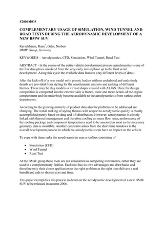
  • 5. Fig. 6: Analysis of Drag Generation The highest level of data reduction is the integration of surface pressure and skin friction to obtain integral forces and moments, equivalent to a wind tunnel measurement. However, this does not allow in-depth investigation in case of unexpected results. One example for the advanced analysis capabilities of simulation is shown in Fig.6 where the vehicle is cut in slices whose contribution to total drag is displayed as a bar chart. In addition, the integration downstream is shown as a solid line, ending at the vehicle’s total drag. Clearly visible are those regions with high drag generation like front end, cooling package, wheels and rear end base. However, also negative drag contributions can be identified where low pressure is acting upon forward facing parts of the surface. This analysis is particularly valuable to compare two variants by simply looking at the differences of these drag distributions. Depending on the flow field topology in the wake, it may happen that exhaust gas enters the passenger compartment through leaks of the rear door. By prescribing the exhaust gas exit velocity and temperature it is possible to visualize the (unsteady) exhaust gas plume via isosurfaces of any temperature (Fig.7). This enables the optimization of end pipe position and direction or, if necessary, even the prevention of exhaust gas recirculation by appropriate modifications of the rear end geometry which would be very cost- intensive if detected later during road tests. Fig. 7: Exhaust Gas Plume .
  • 6. WIND TUNNEL TESTING For reasons of cost and easy handling early wind tunnel testing is conducted using 40% scale models. However, already in this phase underhood and underbody flow is accounted for in a simplified manner. Fig.8 displays the modular assembly of such a model. The actual styling geometry is milled in PU-foam and mounted on top of a frame holding the wind tunnel balance which in turn will be connected to the supporting strut. A second frame houses STL parts representing the drivetrain and underbody panels. A radiator simulator can be adjusted to produce pressure losses of production heat exchangers. It is also possible to measure the actual cooling air mass flow rate with this equipment. This supporting structure is universal, i.e. it can be used with almost all vehicle types. Currently the BMW full scale tunnel has a stationary floor with boundary layer suction. For model testing with ground simulation it can be equipped with a moving belt device where the wheels are supported by external arms separately from the vehicle body and driven by the belt (Fig.9, left). Large scale shape modifications (Fig.10) can easily be tested this way and it is possible to assess more than 20 variants per wind tunnel shift. Details and limitations of the transferability from model to full scale are discussed in (5). Fig. 8: Exploded View of a Modular 40% Scale Model (1) Fig. 9: Model (left at BMW) and Full Scale (right at FKFS) Testing in the Wind Tunnel
  • 7. Fig. 10: Shape Modification in the Wind Tunnel (40% Scale Model in Foam and Clay) Even before design freeze selected variants are also milled in full scale and put together in a similar modular assembly because detail optimization like A-pillar contour or radii of critical edges is questionable in model scale. For these tests external wind tunnels like the one from FKFS in Stuttgart (6) with a 5-belt system (Fig. 9, right) are used if it is felt that this level of ground simulation is necessary. ROAD TESTS The aerodynamic problems investigated on the road using drivable prototypes are those where neither simulation nor the wind tunnel can reproduce reality close enough. A typical example is soiling where it is tested how dust and dirt thrown off by the wheels are propagated in the flow field and where it impinges on the surface. Apart from keeping door handles and frames clean, the goal is to guarantee visibility through the rear window and the side glass onto the wing mirror. To obtain reproducable conditions the vehicle is driven a couple of times with constant speed through a bed covered with a chalk-like material of grain size 1/10mm (Fig.11, left). The test track can also be flooded to distinguish dry and wet soiling. Before and after the tests the vehicle is photographed in a dark room under the same perspective and lighting conditions. Via image processing it is then possible to generate a false color rendering for documentation and comparison among different vehicles (Fig.11, right). Fig. 11: Road Test (Soiling) Similar tests are conducted under winter conditions to analyze the deposition of snow. Here the focus is extended on keeping the rear lights and all air intakes for engine, cooling, brakes
  • 8. and HVAC clear (Fig.12, left). Sometimes snow could even change the overall aerodynamic properties by accumulating at devices like the roof spoiler in Fig.12, right. Fig. 12: Road Test (Snow Deposition) Another test which can not yet be simulated or made in the wind tunnel reliably is the management of rain water. It has to be ensured that A-pillar and roof corner are designed to keep the view on the wing mirror unobstructed and to avoid that water enters the passenger compartment when side window or door are opened. Although thermal management is explored by simulation and wind tunnel as much as possible, there are always final road tests under extremely hot and cold environmental conditions where the surface temperatures of critical components are recorded. SUMMARY AND CONCLUSION It has been demonstrated how the different tools (simulation, wind tunnel and road testing) are employed in a complementary fashion for the aerodynamic development of a new SUV. Realizing the advantages and drawbacks of each method, a benefit.in terms of cost and time can only be achieved by a clever combination and application of these tools to the right problem at the right time. It is desirable to move as much tests as possible upfront because the later requests come up the more cost-intensive and time-consuming these changes will be. NOTE Due to the early deadline for submission of the printed paper well before the launch of the SUV, images of the predecessor had to be used here. REFERENCES (1) Hans Kerschbaum, Norbert Gruen, Peter Hoff, Holger Winkelmann, “On Various Aspects of Testing Methods in Vehicle Aerodynamics”, JSAE Paper 20045445, Yokohama, Japan, 2004 (2) H. Chen, “Volumetric Formulation of the Lattice-Boltzmann Method for Fluid Dynamics: Basic Concepts”,Physical Review E, Volume 58, Number 3, September 1998 (3) Wolf Bartelheimer, “Validation and Application of CFD to Vehicle Aerodynamics”, JSAE Paper 20015332, Yokohama, Japan, 2001
  • 9. (4) Norbert Gruen, “Application of a Lattice-Boltzmann Code in Vehicle Aerodynamics”, von Karman Institute for Fluid Dynamics, Brussels, Belgium, Lecture Series 2005-05, 2005 (5) Jochen Thibaut, “Optimization of Vehicle Design regarding Internal Airflow in the Aerodynamic Development Process”, FISITA Paper F2006M157, 2006 (6) Jochen Wiedemann, Juergen Pothoff , “The New 5-Belt Road Simulation System of the IVK Wind Tunnels”, SAE Paper 03B-102, 2003